BACKGROUND OF THE INVENTION
The present invention relates to a fuel cell
comprising a polymer electrolyte used for portable power
sources, electric vehicle power sources, domestic
cogeneration systems, etc.
A fuel cell comprising a polymer electrolyte
generates electric power and heat simultaneously by
electrochemically reacting a fuel gas containing hydrogen
and an oxidant gas containing oxygen such as air. This
fuel cell is basically composed of a polymer electrolyte
membrane for selectively transporting hydrogen ions and a
pair of electrodes disposed on both surfaces of the polymer
electrolyte membrane. The electrodes comprise a catalyst
layer and a gas diffusion layer which is formed on the
outer surface of the catalyst layer and which has both gas
permeability and electronic conductivity. The catalyst
layer is formed of a mixture of a carbon powder carrying a
platinum group metal catalyst and a hydrogen-ion conductive
polymer electrolyte, and the gas diffusion layer is
composed of, for example, a carbon paper subjected to a
water repellency treatment.
In order to prevent outward leakage and
intermixing of the supplied fuel and oxidant gases, gas
sealing materials or gaskets are arranged so as to
encompass the electrodes and sandwich the polymer
electrolyte membrane. These sealing materials or gaskets
are combined integrally with the electrodes and polymer
electrolyte membrane. This is called "MEA" (electrolyte
membrane electrode assembly). Disposed outside the MEA are
electrically conductive separator plates for mechanically
securing the MEA, and at the same time, interconnecting
adjacent MEAs electrically in series. The separator plates
have, at a portion to come in contact with the MEA, a gas
flow path formed for supplying a reactant gas to the
electrode and removing a generated gas and a surplus gas.
Although the gas flow path may be provided separately from
the separator plates, grooves are usually formed on the
surfaces of the separator plates to serve as the gas flow
path. In a general structure of the fuel cell, the MEAs,
separator plates and cooling sections are alternately
stacked to form a stack of 10 to 200 cells, the cell stack
is sandwiched by end plates with a current collector plate
and an insulating plate interposed between the cell stack
and each end plate, and the resultant is clamped with
clamping bolts from both sides.
In such a polymer electrolyte fuel cell, the
separator plates are often composed of a flat carbon plate
which has, on a portion to come in contact with the anode
or cathode, a gas flow path for supplying the fuel gas or
oxidant gas to the anode or cathode. The separator plates
are commonly flat, without having any difference in height
between the portion on which the gas flow path is formed
and its peripheral portion which is to come in contact with
a surface of the gaskets sandwiching the polymer
electrolyte membrane.
The use of such separator plates will cause the
following problems.
In such a fuel cell, the MEA must be sandwiched by
an anode-side separator plate and a cathode-side separator
plate such that the gas diffusion layers of the anode and the
cathode are in contact with the separator plates while the
polymer electrolyte membrane, the anode and the cathode are
under appropriate pressure. Also, a pair of gaskets
sandwiching the periphery of the electrolyte membrane must be
compressed by the anode-side and cathode-side separator plates
so as to seal the periphery of the MEA. However, when the
separator plates are flat as described above, i.e., when the
portion of the separator plate in contact with the anode or
the cathode and the portion of the separator plate in contact
with the gasket are on the same plane, the degree of
compression of the gaskets determines the degree of contact
between the separator plates and the gas diffusion layers (the
term "the degree of compression of the gaskets" as used herein
refers to the gasket thickness to be reduced by compression,
or the difference in gasket thickness between before and after
the gaskets are compressed). Thus, in order to ensure
sufficient contact between the separator plates and the gas
diffusion layers and therefore minimize the electrical
resistance therebetween, it is necessary to make the degree of
compression of the gaskets extremely large when the gas
diffusion layers are formed of a soft material such as carbon
paper.
Further, in order to reduce the thickness of the MEA
and therefore reduce the size of the fuel cell stack, the gas
diffusion layers to be used in the MEA need to be thinner than
the conventional ones. However, since the conventional
separator plates are unable to sufficiently compress the
gaskets while ensuring sufficient contact with the gas
diffusion layers, it has been difficult to make the MEA
thinner than the conventional one. Thus, the conventional
separator plates have another problem in that they are unable
to be applied to a thinner MEA.
BRIEF SUMMARY OF THE INVENTION
The present invention addresses the above-described
problems. The present invention is directed to an
electrically conductive separator plate for a polymer
electrolyte fuel cell which comprises a cell stack comprising
a plurality of membrane electrode assemblies and a plurality
of conductive separator plates that are stacked alternately,
each of the membrane electrode assemblies comprising a
hydrogen-ion conductive polymer electrolyte membrane, and an
anode and a cathode sandwiching the hydrogen-ion conductive
polymer electrolyte membrane. The conductive separator plate
in accordance with the present invention is formed of a molded
plate comprising a carbon powder and a binder and has a main
portion which is raised from a peripheral portion surrounding
the main portion, the main portion being in contact with the
anode or the cathode and being provided with a gas flow path
for supplying a fuel gas to the anode or a gas flow path for
supplying an oxidant gas to the cathode.
The present invention provides a polymer electrolyte
fuel cell which comprises a cell stack comprising a plurality
of membrane electrode assemblies and a plurality of conductive
separator plates that are stacked alternately, each of the
membrane electrode assemblies comprising a hydrogen-ion
conductive polymer electrolyte membrane, an anode and a
cathode sandwiching the polymer electrolyte membrane, and a
pair of gaskets which surrounds the anode and the cathode and
sandwiches a periphery of the polymer electrolyte membrane,
wherein the plurality of conductive separator plates comprise
at least one pair of an anode-side conductive separator plate
and a cathode-side conductive separator plate sandwiching one
of the membrane electrode assemblies under pressure, each of
the anode-side and cathode-side conductive separator plates is
formed of a molded plate comprising a carbon powder and a
binder, each of the anode-side and cathode-side conductive
separator plates has a main portion which is raised from a
peripheral portion surrounding the main portion, the main
portion of the anode-side conductive separator plate being in
contact with the anode and being provided with a gas flow path
for supplying a fuel gas to the anode, the main portion of the
cathode-side conductive separator plate being in contact with
the cathode and being provided with a gas flow path for
supplying an oxidant gas to the cathode, and the pair of
gaskets is compressed between the peripheral portion of the
anode-side conductive separator plate and the peripheral
portion of the cathode-side conductive separator plate.
While the novel features of the invention are set
forth particularly in the appended claims, the invention, both
as to organization and content, will be better understood and
appreciated, along with other objects and features thereof,
from the following detailed description taken in conjunction
with the drawings.
BRIEF DESCRIPTION OF THE SEVERAL VIEWS OF THE DRAWINGS
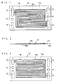
FIG. 1 is a front view of a cathode side of a
conductive separator plate used in a fuel cell in one
embodiment of the present invention.
FIG. 2 is a bottom view of the same separator plate.
FIG. 3 is a back view of the same separator plate.
FIG. 4 is a sectional view of the main part of a
cell stack comprising the same separator plates.
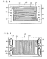
FIG. 5 is a front view of a cathode-side conductive
separator plate in another embodiment of the present invention.
FIG. 6 is a bottom view of the same separator plate.
FIG. 7 is a back view of the same separator plate.
FIG. 8 is a front view of an anode-side conductive
separator plate.
FIG. 9 is a back view of the same separator plate.
FIG. 10 is a sectional view of a part of a
conductive separator plate in still another embodiment of the
present invention.
FIG. 11 is a sectional view of the main part of a
membrane electrode assembly in another embodiment of the
present invention.
DETAILED DESCRIPTION OF THE PREFERRED EMBODIMENTS
The electrically conductive separator plate of the
present invention is formed of a molded plate comprising a
carbon powder and a binder and has a main portion which is
raised from a peripheral portion surrounding the main portion,
the main portion being in contact with the anode or the
cathode and being provided with a gas flow path for supplying
a fuel gas to the anode or a gas flow path for supplying an
oxidant gas to the cathode. The present invention makes it
possible to make the degree of compression of the gaskets
larger, and at the same time, allow the separator plates to
sufficiently press against the gas diffusion layers. Thus,
even with the use of sufficiently thick gaskets, it is
possible to secure contact between the separator plates and
thin gas diffusion layers.
In a preferred mode of the present invention, the
conductive separator plate has a pair of fuel gas manifold
apertures, a pair of oxidant gas manifold apertures and a pair
of cooling water manifold apertures in the peripheral portion
surrounding the main portion in contact with the anode or
cathode.
In another preferred mode of the present invention,
the conductive separator plate has, on one side, a first main
portion which is raised from a peripheral portion surrounding
the first main portion, is in contact with the anode and is
provided with a gas flow path for supplying a fuel gas to the
anode, and has, on the other side, a second main portion which
is raised from a peripheral portion surrounding the second
main portion, is in contact with the cathode and is provided
with a gas flow path for supplying an oxidant gas to the
cathode.
In still another preferred mode of the present
invention, the conductive separator plate comprises a
combination of an anode-side conductive separator plate and a
cathode-side conductive separator plate; the anode-side
conductive separator plate has, on one side, a main portion
which is raised from a peripheral portion surrounding the main
portion, is in contact with the anode and is provided with a
gas flow path for supplying a fuel gas to the anode; the
cathode-side conductive separator plate has, on one side, a
main portion which is raised from a peripheral portion
surrounding the main portion, is in contact with the cathode
and is provided with a gas flow path for supplying an oxidant
gas to the cathode; the anode-side and cathode-side separator
plates are combined with each other such that the other sides
thereof which do not have the gas flow path face each other;
and a cooling water flow path is formed between the combined
anode-side and cathode-side conductive separator plates.
In the above-described separator plates, the
difference in height between the main portion and the
peripheral portion surrounding the main portion is from 80 to
400 µm.
The separator plates in accordance with the present
invention are formed of a molded plate comprising an
electrically conductive carbon powder and a binder. They are
preferably produced by compression molding a green sheet
prepared by extruding a mixture of a carbon powder, for
example, 80 to 70 wt% expanded graphite powder, and a binder,
for example, 20 to 30 wt% phenol resin. When phenol resin is
used as the binder, the compression molding temperature is
appropriately 160°C, and the molding surface pressure is
appropriately from 350 to 500 kgf/cm2.
The above-mentioned green sheet is preferably
compression molded such that the volume of the compressed
sheet becomes 60 to 75 % of the original volume of the green
sheet. In molding separator plates having such shapes as
described in Embodiments below, the compression ratio falls
within the above-mentioned preferable range when the
difference in height between the main portion of the separator
plate in contact with the electrode and the peripheral portion
surrounding the main portion is from 250 to 400 µm. In this
range of 60 to 75 %, the density of the separator plate
becomes almost uniform throughout the entire surface, and the
moldability also becomes favorable. The density of the molded
separator plate becomes from 1.5 to 2.0 g/cm3.
The appropriate thickness of the separator plates in
accordance with the present invention is about 3 mm with
respect to the single separator plate of Embodiment 1, which
serves both as an anode-side separator plate and as a cathode-side
separator plate, and the anode-side and cathode-side
separator plates of Embodiment 2, which constitute a composite
separator plate. The thickness of each of the gaskets
arranged on the anode-side and cathode-side of the polymer
electrolyte membrane is appropriately from 0.3 to 1.0 mm.
In the following, embodiments of the present
invention will be described with reference to drawings.
EMBODIMENT 1
FIGs. 1 to 3 illustrate a conductive separator plate
of this embodiment. FIG. 4 illustrates the main part of a
cell stack comprising the same separator plates.
Numeral 10 represents a single separator plate
serving both as an anode-side conductive separator plate and
as a cathode-side conductive separator plate. The separator
plate 10 has a pair of oxidant gas manifold apertures 12, a
pair of fuel gas manifold apertures 13 and a pair of cooling
water manifold apertures 14. In each pair of manifold
apertures 12, 13 and 14, one of the pair is an inlet-side
manifold aperture, and the other is an outlet-side manifold
aperture.
The separator plate 10 further has, on one side, a
main portion 16c in contact with a cathode, and has, on the
other side, a main portion 16a in contact with an anode. The
main portion 16c is provided with a gas flow path 18 for
supplying an oxidant gas to the cathode, and the main portion
16a is provided with a gas flow path 19 for supplying a fuel
gas to the anode. The main portions 16c and 16a are raised
from peripheral portions 17c and 17a surrounding the main
portions, respectively. The gas flow paths 18 and 19
communicate with the manifold apertures 12 and 13,
respectively, formed in the peripheral portions 17c and 17a.
A membrane electrode assembly (MEA) sandwiched by
the separator plates comprises a hydrogen-ion conductive
polymer electrolyte membrane 21, the cathode 22 and the anode
23 sandwiching a major part, including a central part, of the
polymer electrolyte membrane 21, and a pair of gaskets 25c and
25a.
In the MEA sandwiched by the pair of separator
plates 10, the cathode 22 and the anode 23, which sandwich the
polymer electrolyte membrane 21, are compressed by the main
portion 16c of one of the separator plates and the main
portion 16a of the other separator plate, while the gaskets
25c and 25a, which sandwich the periphery of the polymer
electrolyte membrane 21, are compressed by the peripheral
portion 17c of one of the separator plates and the peripheral
portion 17a of the other separator plate. Thus, by adjusting
the difference in height between the main portion 16c and the
peripheral portion 17c and the difference in height between
the main portion 16a and the peripheral portion 17a in the
separator plates 10, it is possible to appropriately adjust
the degree of contact between the gas diffusion layers of the
cathode and anode and the main portions of the separator
plates as well as the degree of compression of the gaskets.
The difference in height between the main portion 16a and the
peripheral portion 17a is illustrated as "t" in FIG. 4.
In this embodiment, the oxidant gas flow path 18 was
composed of five parallel grooves, while the fuel gas flow
path 19 was composed of three parallel grooves. The number of
grooves constituting each of the gas flow paths, however, is
not limited to the above-described numbers.
The grooves of the gas flow paths were of the
serpentine type comprising a combination of linear portions
and turns. Except for the unavoidable portions, the center
lines of the grooves on one side of the separator plate were
allowed to exactly agree with the center lines of the grooves
on the other side. Thus, when the MEA is sandwiched by a pair
of such separator plates, except for unavoidable portions, the
gas flow paths 18 and 19 on both sides of the polymer
electrolyte membrane 21 are opposed to each other as shown in
FIG. 4.
With respect to the separator plate as described in
this embodiment, the thickness of the portion in contact with
the anode and the cathode is appropriately 3.0 mm, and the
width of the grooves constituting the gas flow paths, the
depth of the grooves and the width of the ribs formed between
the grooves are appropriately about 1.0 mm each.
EMBODIMENT 2
FIGs. 5 to 7 and FIGs. 8 to 9 illustrate a cathode-side
conductive separator plate 30 and an anode-side
conductive separator plate 40, respectively, which constitute
a composite separator plate having a cooling section.
The cathode-side separator plate 30 has a pair of
oxidant gas manifold apertures 32, a pair of fuel gas manifold
apertures 33 and a pair of cooling water manifold apertures 34.
Further, the separator plate 30 has, on one side, a main
portion 36 which is in contact with the cathode, is provided
with a gas flow path 38 for supplying the oxidant gas to the
cathode and is raised from a peripheral portion 37 surrounding
the main portion. The anode-side separator plate 40 has a
pair of oxidant gas manifold apertures 42, a pair of fuel gas
manifold apertures 43 and a pair of cooling water manifold
apertures 44. Further, the separator plate 40 has, on one side,
a main portion 46 which is in contact with the anode, is
provided with a gas flow path 49 for supplying the fuel gas to
the anode and is raised from a peripheral portion 47
surrounding the main portion. The gas flow paths 38 and 49
communicate with the manifold apertures 32 and 43,
respectively, formed in the peripheral portions 37 and 47.
The pair of oxidant gas manifold apertures 32, the
pair of fuel gas manifold apertures 33 and the pair of cooling
water manifold apertures 34, formed in the separator plate 30,
communicate with the pair of oxidant gas manifold apertures 42,
the pair of fuel gas manifold apertures 43 and the pair of
cooling water manifold apertures 44, formed in the separator
plate 40, respectively.
The backside of the cathode-side separator plate 30
is a flat surface without any difference in height and is
provided with a cooling water flow path 35 communicating with
the pair of manifold apertures 34. The backside of the
separator plate 30 is further provided with grooves 31c and
31a surrounding the oxidant gas manifold apertures 32 and the
fuel gas manifold apertures 33, respectively, and a groove 31w
surrounding the cooling water manifold apertures 34 and the
cooling water flow path 35.
Likewise, the backside of the anode-side separator
plate 40 is a flat surface without any difference in height
and is provided with a cooling water flow path 45
communicating with the pair of manifold apertures 44. The
backside of the separator plate 40 is further provided with
grooves 41c and 41a surrounding the oxidant gas manifold
apertures 42 and the fuel gas manifold apertures 43,
respectively, and a groove 41w surrounding the cooling water
manifold apertures 44 and the cooling water flow path 45.
The cathode-side separator plate 30 and the anode-side
separator plate 40 are combined to each other such that
their backsides, i.e., the surfaces having the cooling water
flow paths, face each other, and the combined separator plates
are inserted between the MEAs. On the backsides of the
separator plates, an O-ring is inserted between the grooves
31c and 41c, between the grooves 31a and 41a, and between the
grooves 31w and 41w, thereby to prevent outward leakage of
cooling water from between the separator plates 30 and 40.
In this embodiment, the cooling water flow path was
formed on both of the separator plates 30 and 40, but it may
be formed only on one of the separator plates.
The composite separator plate of this embodiment has
a cooling section for flowing cooling water, and except for
the presence of the cooling section, its cathode-facing side
and its anode-facing side are basically the same as the
separator plate of Embodiment 1.
EMBODIMENT 3
FIG. 10 illustrates a periphery of a separator plate
of this embodiment.
A separator plate 10A has ribs 26c and 26a which are
as high as the main portions 16c and 16a at the end of the
peripheral portions 17c and 17a of the separator plate 10 of
Embodiment 1. The ribs 26c and 26a prevent the gaskets from
getting out of position when a cell stack is fabricated. The
ribs 26c and 26a are not necessarily as high as the main
portions 16c and 16a, and may be lower than the main portions
16c and 16a.
EMBODIMENT 4
A modified example of the gasket will be described
in this embodiment.
FIG. 11 illustrates a gasket 27, in which a portion
covering the cathode-side of a polymer electrolyte membrane
21A is connected and integrated to a portion covering the
anode-side at through holes 28 of the polymer electrolyte
membrane 21A and at a portion covering the edge of the
membrane 21A. Such a gasket can be produced, for example, by
integrally molding a gasket on the periphery of a polymer
electrolyte membrane having a large number of through holes.
For this kind of gasket, the entire disclosure of
PCT/JP02/00736 including specification, claims, drawings and
summary are incorporated herein by reference in its entirety.
In fabricating a fuel cell system using the
separator plates in accordance with the present invention, it
is preferable to stack the MEAs and the separator plates of
Embodiment 1 alternately and insert, as appropriate, the
composite separator plate of Embodiment 2 having the cooling
section between the MEAs.
In the following, an example of the present
invention will be described.
EXAMPLE 1
First, a conductive carbon powder having an average
primary particle size of 30 nm (Ketjen Black EC, manufactured
by Akzo Chemie Company of the Nederlands) was allowed to carry
50 wt% platinum particles having an average particle size of
about 30 Å, to prepare a cathode catalyst powder. The same
conductive carbon powder was allowed to carry platinum
particles and ruthenium particles, 25 wt% each, having an
average particle size of about 30 Å, to prepare an anode
catalyst powder.
A dispersion of each of the catalyst powders in
isopropanol was mixed with a dispersion of perfluorocarbon
sulfonic acid powder in ethyl alcohol to prepare a cathode
catalyst paste and an anode catalyst paste. Each of the
pastes was applied, by screen printing, onto one side of a 250
µm thick carbon fiber nonwoven fabric to form a cathode
catalyst layer and an anode catalyst layer. This gave a
carbon fiber non-woven fabric with the anode catalyst layer
formed thereon and a carbon fiber non-woven fabric with the
cathode catalyst layer formed thereon. In each of the
electrodes thus formed, the content of catalyst metal was 0.5
mg/cm2, and the content of perfluorocarbon sulfonic acid was
1.2 mg/cm2.
These carbon fiber non-woven fabrics were bonded, by
hot pressing, to both sides of the center part of a hydrogen-ion
conductive polymer electrolyte membrane having an area
slightly larger than that of the electrode in such a manner
that each of the catalyst layers was in contact with the
electrolyte membrane. The polymer electrolyte membrane used
in this example was a thin film of perfluorocarbon sulfonic
acid (Nafion 112 manufactured by E.I. Du Pont de Nemours & Co.
Inc., the United State). Further, gaskets, punched out into
the almost same shape as that of the outer peripheral portion
of the separator plate, were bonded to both sides of the
electrolyte membrane by hot pressing so as to surround the
electrodes and sandwich the electrolyte membrane. This gave
an MEA.
On the assumption that this MEA was combined with
two separator plates of Embodiment 1 to fabricate a unit cell
as shown in FIG. 4, simulation testing was conducted to obtain
the sealing surface pressure and the reaction force thereto
exerted onto the gaskets of the MEA by varying the difference
in height ("t" of FIG. 4) between the main portion and the
peripheral portion of the separator plates.
In this MEA, the pair of gaskets sandwiching the
periphery of the 30 µm thick polymer electrolyte membrane was
made of a fluoroelstomer (VITON GBL, manufactured by DuPont
Dow Elastomer Japan), and the free thickness of each of the
pair of gaskets was 0.8 mm. In this case, when the portion of
the MEA having the cathode and anode is compressed by the main
portions of the separator plates to have a thickness of 0.5 mm,
the degree of contact between the electrodes and the separator
plates becomes most appropriate. With respect to the
separator plates, the thickness of the portion in contact with
the cathode and the anode was 3.0 mm, and the difference in
height between the main portion and the peripheral portion on
one side was varied in a range up to 500 µm.
Under the above-described conditions, the sealing
surface pressure and the reaction force thereto were measured
when the main portions of the separator plates compressed the
gaskets so as to make the thickness of the portion of the MEA
having the electrodes the above-mentioned 0.5 mm. The results
are shown in Table 1.
| Difference in height (t) (µm) | Sealing surface pressure (MPa) | Reaction Force (N/mm) |
| 0 | 69 | 120 |
| 50 | 25 | 57 |
| 80 | 11 | 16 |
| 200 | 4 | 3 |
| 300 | 2 | 0.7 |
| 400 | 1 | 0.1 |
| 500 | 0.3 | 0.05 |
In such a polymer electrolyte fuel cell, when the
sealing surface pressure of the gaskets is less than 1 MPa,
gas leakage takes place. When the reaction force to the
sealing surface pressure is more than 20 N/mm, on the other
hand, the clamping pressure of the cell stack is required to
be extremely large. Thus, both cases are of little practical
use. The results of the simulation testing of Table 1
indicate that the difference in height between the main
portion of the separator plate in contact with the electrode
and the peripheral portion surrounding the main portion is
appropriately from 80 to 400 µm.
As described above, the present invention enables
sufficient compression of the gaskets to produce the gas-leakage-free
sealing effect while ensuring sufficient contact
between the gas diffusion layers of the electrodes and the
separator plates. Therefore, the present invention enables
reduction in contact resistance between the electrodes and the
separator plates and application of thinner gas diffusion
layers.
Although the present invention has been described in
terms of the presently preferred embodiments, it is to be
understood that such disclosure is not to be interpreted as
limiting. Various alterations and modifications will no doubt
become apparent to those skilled in the art to which the
present invention pertains, after having read the above
disclosure. Accordingly, it is intended that the appended
claims be interpreted as covering all alterations and
modifications as fall within the true spirit and scope of the
invention.