JP5051606B2 - Fuel cell - Google Patents
Fuel cell Download PDFInfo
- Publication number
- JP5051606B2 JP5051606B2 JP2005084435A JP2005084435A JP5051606B2 JP 5051606 B2 JP5051606 B2 JP 5051606B2 JP 2005084435 A JP2005084435 A JP 2005084435A JP 2005084435 A JP2005084435 A JP 2005084435A JP 5051606 B2 JP5051606 B2 JP 5051606B2
- Authority
- JP
- Japan
- Prior art keywords
- manifold
- refrigerant
- fuel cell
- separator
- flow path
- Prior art date
- Legal status (The legal status is an assumption and is not a legal conclusion. Google has not performed a legal analysis and makes no representation as to the accuracy of the status listed.)
- Expired - Fee Related
Links
Images


Classifications
-
- H—ELECTRICITY
- H01—ELECTRIC ELEMENTS
- H01M—PROCESSES OR MEANS, e.g. BATTERIES, FOR THE DIRECT CONVERSION OF CHEMICAL ENERGY INTO ELECTRICAL ENERGY
- H01M8/00—Fuel cells; Manufacture thereof
- H01M8/02—Details
- H01M8/0271—Sealing or supporting means around electrodes, matrices or membranes
-
- H—ELECTRICITY
- H01—ELECTRIC ELEMENTS
- H01M—PROCESSES OR MEANS, e.g. BATTERIES, FOR THE DIRECT CONVERSION OF CHEMICAL ENERGY INTO ELECTRICAL ENERGY
- H01M8/00—Fuel cells; Manufacture thereof
- H01M8/02—Details
- H01M8/0202—Collectors; Separators, e.g. bipolar separators; Interconnectors
- H01M8/0258—Collectors; Separators, e.g. bipolar separators; Interconnectors characterised by the configuration of channels, e.g. by the flow field of the reactant or coolant
-
- H—ELECTRICITY
- H01—ELECTRIC ELEMENTS
- H01M—PROCESSES OR MEANS, e.g. BATTERIES, FOR THE DIRECT CONVERSION OF CHEMICAL ENERGY INTO ELECTRICAL ENERGY
- H01M8/00—Fuel cells; Manufacture thereof
- H01M8/02—Details
- H01M8/0202—Collectors; Separators, e.g. bipolar separators; Interconnectors
- H01M8/0267—Collectors; Separators, e.g. bipolar separators; Interconnectors having heating or cooling means, e.g. heaters or coolant flow channels
-
- H—ELECTRICITY
- H01—ELECTRIC ELEMENTS
- H01M—PROCESSES OR MEANS, e.g. BATTERIES, FOR THE DIRECT CONVERSION OF CHEMICAL ENERGY INTO ELECTRICAL ENERGY
- H01M8/00—Fuel cells; Manufacture thereof
- H01M8/24—Grouping of fuel cells, e.g. stacking of fuel cells
- H01M8/2465—Details of groupings of fuel cells
- H01M8/2483—Details of groupings of fuel cells characterised by internal manifolds
-
- H—ELECTRICITY
- H01—ELECTRIC ELEMENTS
- H01M—PROCESSES OR MEANS, e.g. BATTERIES, FOR THE DIRECT CONVERSION OF CHEMICAL ENERGY INTO ELECTRICAL ENERGY
- H01M8/00—Fuel cells; Manufacture thereof
- H01M8/10—Fuel cells with solid electrolytes
- H01M2008/1095—Fuel cells with polymeric electrolytes
-
- H—ELECTRICITY
- H01—ELECTRIC ELEMENTS
- H01M—PROCESSES OR MEANS, e.g. BATTERIES, FOR THE DIRECT CONVERSION OF CHEMICAL ENERGY INTO ELECTRICAL ENERGY
- H01M8/00—Fuel cells; Manufacture thereof
- H01M8/02—Details
- H01M8/0202—Collectors; Separators, e.g. bipolar separators; Interconnectors
- H01M8/0204—Non-porous and characterised by the material
- H01M8/0223—Composites
- H01M8/0228—Composites in the form of layered or coated products
-
- H—ELECTRICITY
- H01—ELECTRIC ELEMENTS
- H01M—PROCESSES OR MEANS, e.g. BATTERIES, FOR THE DIRECT CONVERSION OF CHEMICAL ENERGY INTO ELECTRICAL ENERGY
- H01M8/00—Fuel cells; Manufacture thereof
- H01M8/02—Details
- H01M8/0271—Sealing or supporting means around electrodes, matrices or membranes
- H01M8/0276—Sealing means characterised by their form
-
- Y—GENERAL TAGGING OF NEW TECHNOLOGICAL DEVELOPMENTS; GENERAL TAGGING OF CROSS-SECTIONAL TECHNOLOGIES SPANNING OVER SEVERAL SECTIONS OF THE IPC; TECHNICAL SUBJECTS COVERED BY FORMER USPC CROSS-REFERENCE ART COLLECTIONS [XRACs] AND DIGESTS
- Y02—TECHNOLOGIES OR APPLICATIONS FOR MITIGATION OR ADAPTATION AGAINST CLIMATE CHANGE
- Y02E—REDUCTION OF GREENHOUSE GAS [GHG] EMISSIONS, RELATED TO ENERGY GENERATION, TRANSMISSION OR DISTRIBUTION
- Y02E60/00—Enabling technologies; Technologies with a potential or indirect contribution to GHG emissions mitigation
- Y02E60/30—Hydrogen technology
- Y02E60/50—Fuel cells
Description
本発明は、燃料電池に係り、特に、冷媒による燃料電池冷却の効率向上に有効な技術に関する。 The present invention relates to a fuel cell , and more particularly to a technique effective for improving the efficiency of fuel cell cooling by a refrigerant.
例えば、固体高分子電解質型の燃料電池は、膜−電極アッセンブリ(MEA:Membrane-Electrode Assembly )とセパレータとからなるセルを積層して構成される。MEAは、イオン交換膜からなる電解質膜と、この電解質膜の一面に配置された触媒層からなる電極(アノード)および電解質膜の他面に配置された触媒層からなる電極(カソード)と、からなる。 For example, a solid polymer electrolyte type fuel cell is configured by stacking cells including a membrane-electrode assembly (MEA) and a separator. The MEA includes an electrolyte membrane composed of an ion exchange membrane, an electrode (anode) composed of a catalyst layer disposed on one surface of the electrolyte membrane, and an electrode (cathode) composed of a catalyst layer disposed on the other surface of the electrolyte membrane. Become.
図5〜図7に示したものは、MEAを挟持するセパレータ12a,12bである。セパレータ12a,12bの端部には、冷却水を給排するマニホールド43,53が矩形状に貫通形成されている。また、MEAの電極に面する部分が例えばプレス成形されることで、表裏各面に複数の凸状のリブ13aが形成されており、これらリブ13aの間に、冷却水導入流路32a,冷却水主流路32,及び冷却水導出流路32bが形成されている。
5 to 7 are
セパレータ12a,12b間に図示しないMEAを挟み込んで構成される単セルを複数積層して燃料電池スタックが構成される。このとき、隣接する一方の単セルのセパレータ12aと、他方の単セルのセパレータ12bとの間には、冷却水主流路32とその入口側及び出口側に連なる冷却水導入流路32a及び冷却水導出流路32bが画成される。これら流路32a,32,32bを流れる冷却水は、図6に示すように、両セパレータ12a,12b間に介装されたシール部材(ガスケット)101cによってシールされる。
A fuel cell stack is configured by stacking a plurality of single cells configured by sandwiching an MEA (not shown) between the
燃料電池の発電時においては、図5及び図7に示したように、入口側のマニホールド43から供給された冷却水は、矢印Aに示すように流路32a,32,32bを流れる。冷却水は、MEAの発電領域(MEAの電極に面する領域)に対応した部分(エリア)を冷却した後、出口側のマニホールド53に流れ込んで排出される。
このように構成された燃料電池では、シール部材101cを貼り付けるためのスペースをセパレータ12a,12bの周縁部に設ける必要がある。すなわち、シール部材101cは、非圧縮状態での設置スペースに加えて、圧縮状態でのセパレータ面方向の潰れ量を予め見込んでおいて、マニホールド43,53からセパレータ外周側に離れた位置に固定される。
In the fuel cell configured as described above, it is necessary to provide a space for attaching the
したがって、マニホールド43,53とシール部材101cの内側ラインとの間には冗長な隙間Sが生じ、図5および図7に示したように、この隙間に回り込んだ冷却水の一部がシール部材101cに沿って矢印Bのように流れる。矢印Bに沿う領域、つまり、MEAの発電領域に非対応の部分(エリア)は、発熱する発電領域に面しておらず、冷却が不必要な領域であるため、この領域に冷却水が回り込むことで冷却効率が低下するという課題があった。
Therefore, a redundant gap S is generated between the
本発明は上記事情に鑑みて成されたものであり、冷媒による冷却効率を向上させることができる燃料電池を提供することを目的とする。 The present invention has been made in view of the above circumstances, and an object thereof is to provide a fuel cells which can improve the cooling efficiency of the refrigerant.
本発明のポイントは、冷却効率を向上させるために、セパレータの冷媒(冷却液)流路において、MEAの発電領域に対応しない領域への冷媒(冷却液)の流れを低減することにある。すなわち、セパレータの一方の面に隣接配置されるMEAの発電領域の周縁部に対応させて冷媒(冷却液)流路の周縁部を形成することにある。 The point of the present invention is to reduce the flow of the coolant (coolant) to the region not corresponding to the power generation region of the MEA in the coolant (coolant) channel of the separator in order to improve the cooling efficiency. That is, the peripheral portion of the refrigerant (coolant) flow path is formed in correspondence with the peripheral portion of the power generation region of the MEA disposed adjacent to one surface of the separator.
例えば、冷媒(冷却液)流路の周縁部にシール部材を配置する場合においては、シール部よりもセパレータ面方向の内側に、シール部材側への冷媒の流れを規制する冷媒規制部が設けられる。 For example, in the case where the seal member is disposed at the peripheral portion of the refrigerant (coolant) flow path, a refrigerant regulating portion that regulates the flow of the refrigerant toward the seal member is provided on the inner side in the separator surface direction than the seal portion. .
上記の課題を解決するため、本発明の燃料電池は、冷媒流路形成面に冷媒流路を有すると共に該冷媒流路に冷媒を供給する第1のマニホールド及び前記冷媒流路に導入された冷媒を排出する第2のマニホールドが貫通形成されたセパレータと、該セパレータの冷媒流路形成面側に積層された積層部材と、前記セパレータの前記冷媒流路形成面とは反対側の面に積層された膜−電極アッセンブリと、前記セパレータと前記積層部材との間に前記冷媒流路と前記第1及び第2のマニホールドを囲繞するように介在して前記冷媒流路形成面側に導入された冷媒をシールするシール部と、を備えた燃料電池であって、前記シール部が囲繞する範囲には、前記膜−電極アッセンブリの発電領域に対応する部分に加えてその外側の非発熱領域に対応する部分も含まれ、前記シール部のうち前記第1のマニホールドの近傍に配置された第1のマニホールド近傍部と前記第1のマニホールドとの間には、前記第1のマニホールド近傍部から一定の間隔を隔てて前記第1のマニホールドに沿って連続的に形成され、前記第1のマニホールドから前記冷媒流路形成面側に供給される冷媒の前記第1のマニホールド近傍部側への流れを規制する凸部よりなる冷媒規制部が設けられており、前記凸部よりなる冷媒規制部の一部と前記第1のマニホールドの内壁とが、前記第1のマニホールドの貫通方向に面一とされているものである。 In order to solve the above-described problems, a fuel cell according to the present invention has a refrigerant flow path on a refrigerant flow path forming surface, a first manifold that supplies the refrigerant to the refrigerant flow path, and a refrigerant introduced into the refrigerant flow path. The separator is formed by penetrating the second manifold for discharging the gas, the laminated member laminated on the refrigerant flow path forming surface side of the separator, and the separator on the surface opposite to the refrigerant flow path forming surface. Refrigerant introduced to the refrigerant flow path forming surface side so as to surround the refrigerant flow path and the first and second manifolds between the membrane-electrode assembly, the separator and the laminated member A fuel cell comprising a seal portion that seals a portion of the membrane-electrode assembly corresponding to a non-heat generation region in addition to a portion corresponding to a power generation region of the membrane-electrode assembly. Part The first manifold vicinity portion disposed in the vicinity of the first manifold in the seal portion and the first manifold are spaced apart from the first manifold vicinity portion. A protrusion that is continuously formed along the first manifold and that regulates the flow of refrigerant supplied from the first manifold to the refrigerant flow path forming surface side toward the first manifold vicinity. A refrigerant restricting portion comprising a portion is provided, and a part of the refrigerant restricting portion comprising the convex portion and the inner wall of the first manifold are flush with each other in the penetrating direction of the first manifold. It is.
このような構成によれば、シール部近傍のような冷却を行う必要がない領域、すなわち、発電領域外に冷媒の一部が回り込むことが規制される。つまり、マニホールドを出た冷媒は、冷却を行う必要のない領域への回り込みを抑制されながら各冷媒流路に導入される。 According to such a configuration, it is restricted that a part of the refrigerant goes around to the outside of the power generation area, that is, in the vicinity of the seal portion where it is not necessary to perform cooling. That is, the refrigerant exiting the manifold is introduced into each refrigerant flow path while being prevented from entering a region where cooling is not required.
前記冷媒規制部は、前記シール部のうち前記第1のマニホールドの開口縁に沿って延びる部位の内側ラインの近傍に設けられていてもよい。 The refrigerant restricting portion may be provided in the vicinity of an inner line of a portion extending along the opening edge of the first manifold in the seal portion.
前記冷媒規制部は、前記セパレータの冷媒流路形成面側に設けられた凸部よりなるので、凸部の先端がこれと向かい合った積層部材と接することで、冷媒が凸部を乗り越えてシール近傍に回り込むことが規制される。凸部はセパレータと一体成形されたものでもよいし、別体に成形されてセパレータに固定されたものであってもよい。 The refrigerant restricting portion is formed of a convex portion provided on the refrigerant flow path forming surface side of the separator, so that the refrigerant gets over the convex portion and close to the seal when the tip of the convex portion is in contact with the laminated member facing it. Sneaking in is restricted. The convex portion may be formed integrally with the separator, or may be formed separately and fixed to the separator.
前記冷媒規制部が前記シール部よりも圧縮荷重に対して変形し難い構造であってもよい。The refrigerant restricting portion may have a structure that is less likely to be deformed by a compressive load than the seal portion.
この構成によれば、冷媒規制部が例えばガスケットのようには容易に変形しないので、単に冷媒流れを規制するだけでなく、セパレータを所定間隔で積層するためのスペーサとしても機能させることができる。 According to this configuration, since the refrigerant restricting portion is not easily deformed like, for example, a gasket, it can function not only as a refrigerant flow but also as a spacer for laminating separators at predetermined intervals.
前記冷媒規制部は、導電性を有していてもよい。この場合、前記冷媒規制部は、導電性を有する前記セパレータに一体成形されたものであってもよい。 The refrigerant regulating part may have conductivity. In this case, the refrigerant restricting portion may be integrally formed with the separator having conductivity.
前記シール部のうち前記第2のマニホールドの近傍に配置された第2のマニホールド近傍部と前記第2のマニホールドとの間にも、前記第2のマニホールド近傍部から一定の間隔を隔てて前記第2のマニホールドに沿って連続的に形成され、前記冷媒流路から前記第2のマニホールドへと排出される冷媒の前記第2のマニホールド近傍部側への流れを規制する凸部よりなる冷媒規制部が設けられており、の凸部よりなる冷媒規制部の一部と前記第2のマニホールドの内壁とが、前記第2のマニホールドの貫通方向に面一とされていてもよい。 Of the seal portion, the second manifold vicinity portion disposed near the second manifold and the second manifold are also spaced apart from the second manifold vicinity portion by a predetermined distance . A refrigerant regulating portion formed of a convex portion that is continuously formed along the two manifolds and regulates the flow of the refrigerant discharged from the refrigerant flow path to the second manifold toward the second manifold vicinity. A part of the refrigerant regulating portion formed by the convex portion and the inner wall of the second manifold may be flush with each other in the penetrating direction of the second manifold.
本発明によれば、シール部よりもセパレータ面方向の内側に冷媒規制部が設けられているので、冷却を行う必要がない領域への冷媒の回り込みが規制され、燃料電池の冷却効率を向上させることができる。 According to the present invention, since the refrigerant regulating portion is provided on the inner side in the separator surface direction than the seal portion, the circulation of the refrigerant to an area where cooling is not necessary is regulated, and the cooling efficiency of the fuel cell is improved. be able to.
次に、本発明の一実施形態について図1乃至図4を参照して説明する。まず図4に示した燃料電池の単セル構造について概略を説明する。図4に示した単セル2は、MEA11と、MEA11を挟持する一対のセパレータ14a,14bとで構成され、全体として積層形態を有している。詳細を後述するように、MEA11と各セパレータ14a,14bとは、それらの間の周辺部において第1シール部材101a,101bによりシールされている。
Next, an embodiment of the present invention will be described with reference to FIGS. First, an outline of the single cell structure of the fuel cell shown in FIG. 4 will be described. The
MEA11は、高分子材料のイオン交換膜からなる電解質膜21と、電解質膜21を両面から挟んだ一対の電極22a,22b(カソードおよびアノード)とで構成されている。セパレータ14a,14bには、電極22a,22bに面する部分をプレス成形されることで表裏各面に複数の凸状のリブ13が形成されている。これらリブ13の間に、酸化ガスのガス流路31aまたは水素ガスのガス流路31bや、冷却水主流路(冷媒流路)32が形成される。
The MEA 11 includes an electrolyte membrane 21 made of a polymer material ion exchange membrane and a pair of
具体的には、セパレータ14aの電極22a側となる内側の面には、酸化ガスのガス流路31aが複数形成され、その反対側の外側の面(冷媒流路形成面)には、冷却水主流路32が複数形成されている。同様に、セパレータ14bの電極22b側となる内側の面には、水素ガスのガス流路31bが複数形成され、その反対側の外側の面(冷媒流路形成面)には、冷却水主流路32が複数形成されている。
Specifically, a plurality of
セパレータ14a,14bの一方の端部(短辺部)には、酸化ガスの入口側のマニホールド41、水素ガスの入口側のマニホールド42、および冷却水(冷媒)の入口側のマニホールド(第1のマニホールド)43が矩形状に貫通形成されている。セパレータ14a,14bの他方の端部(短辺部)には、酸化ガスの出口側のマニホールド51、水素ガスの出口側のマニホールド52、および冷却水の出口側のマニホールド(第2のマニホールド)53が矩形状に貫通形成されている。
At one end (short side) of the
第1シール部材101aは、セパレータ14aの酸化ガスに関連する通路(ガス流路31a、マニホールド41,51)を全てMEA11側にて囲繞する一続きの第1メインシール部111aと、セパレータ14aの水素ガスの入口側および出口側のマニホールド42,52をMEA11側にて囲繞する枠状の第1サブシール部112a,113aと、セパレータ14aの冷却水の入口側および出口側のマニホールド43,53をMEA11側にて囲繞する枠状の第1サブシール部114a,115aとで構成されている。第1サブシール部112a〜115aは、それぞれ第1メインシール部111aと分離している。
The
同様に、第1シール部材101bは、セパレータ14bの水素ガスに関連する通路(ガス流路31b、マニホールド42,52)を全てMEA11側にて囲繞する一続きの第1メインシール部111bと、セパレータ14bの酸化ガスの入口側および出口側のマニホールド41,51をMEA11側にて囲繞する枠状の第1サブシール部116b,117bと、セパレータ14bの冷却水の入口側および出口側のマニホールド43,53をMEA11側にて囲繞する枠状の第1サブシール部114b,115bとで構成されている。第1サブシール部114b〜117bは、それぞれ第1メインシール部111bと分離している。
Similarly, the
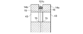
このようにして単セル2が構成され、複数の単セル2間に第2シール部材(シール部)101cを介装してこれら単セル2を積層することにより、燃料電池が構成される。第2シール部材101cは、セパレータ14b(14a)の冷却水に関連する通路(冷却水主流路32、冷却水導入流路32a、冷却水導出流路32b、マニホールド43,53)を全て、隣接する単セル2側にて囲繞する一続きの第1メインシール部111cを有している。
In this way, the
また、第2シール部材101cは、第1シール部材101a,101bと同様に、水素ガス用の第1サブシール部112c、113cと、酸化ガス用の第1サブシール部116c、117cとを、それぞれ第1メインシール部111cから分離した状態で有している。
Similarly to the
図1は、図4に示したセパレータ14a(14b)のマニホールド43及びその周辺部分を拡大した図である。マニホールド43と図外の冷却水主流路32との間には、凸状のリブ13aが複数設けられており、これらリブ13a間がマニホールド43からの冷却水を冷却水主流路32に導入する冷却水導入流路32aとなっている。同様に、冷却水主流路32とマニホールド53との間にも凸状のリブが複数設けられており、これらリブ間が冷却水主流路32からマニホールド53に冷却水を導出する冷却水導出流路32bとなっている。
FIG. 1 is an enlarged view of the manifold 43 and its peripheral portion of the
マニホールド43を介してセパレータ14a(14b)の冷媒流路形成面側に供給された冷却水は、冷却水導入流路32aを通って冷却水主流路32に導かれ、該冷却水主流路32に面する発電領域を冷却しながら、冷却水導出流路32bを通ってマニホールド53に排出される。これら冷却水導入流路32a及び冷却水導出流路32bは、上記冷却水主流路32と同様、本発明における冷媒流路の一部を構成している。
The cooling water supplied to the refrigerant flow path forming surface side of the
セパレータ14a,14bには更に、マニホールド43,冷却水導入流路32a,冷却水主流路32,冷却水導出流路32b,及びマニホールド53を包括的に取り囲むように、外周リブ(冷媒規制部、凸部)15が設けられている。外周リブ15は、セパレータ14a,14bに形成された堤状をなす定寸構造の突起からなり、その横断面形状は例えば矩形状となっている。
The
すなわち、本実施形態に係る外周リブ15は、セパレータ14a,14b間を流れる冷媒をシールする第2シール部材101cよりもセパレータ面方向の内側、より具体的には、第2シール部材101cの内側ラインに隣接する部位に設けられており、冷却水導入流路32a,冷却水主流路32,及び冷却水導出流路32bの形成領域を含む発電領域と、冷却水が給排されるマニホールド43,53とを取り囲んだ状態で設けられている。
That is, the outer
外周リブ15は、発電効率の低下抑制のため導電性であることが好ましい。例えば、セパレータ14a,14bをカーボンやメタルにより構成し、外周リブ15をセパレータ14a,14bと一体成形することにより、外周リブ15を導電性とすることができる。また、かかる構成によれば、セパレータ14a,14bと別体の外周リブ15をこれらセパレータ14a,14bに後で固定する場合と比較して、部品点数及び組立工数を削減することができる。
The outer
隣接する一方の単セル2のセパレータ14aと、他方の単セル2のセパレータ(積層部材)14bとは、図3のように各々の外周リブ15の先端を突き合わせた状態で積層される。その際、両セパレータ14a,14b間に第2シール部材101cが介装されることによって、マニホールド43,冷却水導入流路32a,冷却水主流路32,及び冷却水導出流路32bをこの順に流れてマニホールド53から排出される冷却水が液密にシールされる。
The
なお、本実施形態の外周リブ15は、セパレータ14a,14bと一体に成形されたものであり、セル積層方向の圧縮荷重(締付荷重)に対し、第2シール部材101cを含む他の全シール部材のようには容易に変形しない定寸構造とされているので、各セパレータ14a,14bを所定間隔で積層するためのスペーサとしても機能する。
The outer
このように構成された燃料電池の発電時においては、マニホールド43から供給された冷却水が、外周リブ15によって第2シール部材101cの内側ライン側への流れが阻止されるように案内(規制)されて、冷却水導入流路32aを通って各冷却水主流路32に流入する。この冷却水は発電領域を冷却しながら、冷却水導出流路32bを通って出口側のマニホールド53に排出される。
During power generation of the fuel cell configured as described above, the cooling water supplied from the manifold 43 is guided (regulated) so that the outer
以上のとおり、本実施形態によれば、マニホールド43を出てセパレータ面方向に広がろうとする冷却水の流れが外周リブ15によって発電領域側に案内されることによって、マニホールド43と第2シール部材101cとの間の領域、つまり、発電領域外の非発熱領域に冷却水が回り込むことが規制され、図7の矢印Bで示されたような第2シール部材101cに沿った冷却水流れの発生を抑えることができる。よって、冷却水による燃料電池の冷却効率を向上させることが可能となる。
As described above, according to the present embodiment, the flow of the cooling water that leaves the manifold 43 and spreads in the separator surface direction is guided to the power generation region side by the outer
特に、外周リブ15の一部がマニホールド43の開口縁に沿って設けられているので、マニホールド43からセパレータ面に供給された冷却水が冷却を行う必要がない領域に回り込むことを効果的に抑制しつつ、当該冷却水を各冷却水主流路32に導入することができる。また、冷却水導出流路32bを出た冷却水は、外周リブ15に案内されながら、遠回りをすることなくマニホールド53に排出される。
<他の実施形態>
上記実施形態では、外周リブ15がマニホールド43,冷却水導入流路32a,冷却水主流路32,冷却水導出流路32b,及びマニホールド53の全てを取り囲むように設けられていたが、少なくとも外周リブ15の一部がマニホールド43,53の開口縁のうちセパレータ外周側に面した部位に沿って設けられていてもよい。
Particularly, since a part of the outer
<Other embodiments>
In the above embodiment, the outer
また、外周リブ15は、向かい合ったセパレータ14a,14bの少なくともいずれか一方に設けられていればよい。さらに、上記のように外周リブ15をセパレータ14a,14bと一体成形してもよいが、セパレータ14a,14bとは別体に外周リブ15を成形し、セパレータに14a,14bに対して固定するようにしてもよい。
Moreover, the outer
また、セパレータと、該セパレータの冷媒流路形成面側に積層された積層部材との間に介在して冷媒流路を流れる冷媒をシールするシール部は、上記実施形態に係る第2シール部材101cのようなガスケットに限らず、接着剤でもよい。
Further, the seal portion that is interposed between the separator and the laminated member laminated on the refrigerant flow path forming surface side of the separator and seals the refrigerant flowing through the refrigerant flow path is the
13…リブ、14a,14b…セパレータ、15…外周リブ(冷媒規制部、凸部)、101c…第2シール部材(シール部)、32…冷却水主流路(冷媒流路)、32a…冷却水導入流路(冷媒流路)、32b…冷却水導出流路(冷媒流路)、43,53…マニホールド
DESCRIPTION OF
Claims (6)
前記シール部が囲繞する範囲には、前記膜−電極アッセンブリの発電領域に対応する部分に加えてその外側の非発熱領域に対応する部分も含まれ、
前記シール部のうち前記第1のマニホールドの近傍に配置された第1のマニホールド近傍部と前記第1のマニホールドとの間には、前記第1のマニホールド近傍部から一定の間隔を隔てて前記第1のマニホールドに沿って連続的に形成され、前記第1のマニホールドから前記冷媒流路形成面側に供給される冷媒の前記第1のマニホールド近傍部側への流れを規制する凸部よりなる冷媒規制部が設けられており、
前記凸部よりなる冷媒規制部の一部と前記第1のマニホールドの内壁とが、前記第1のマニホールドの貫通方向に面一とされている燃料電池。 A separator having a coolant channel on the coolant channel forming surface and a first manifold for supplying the coolant to the coolant channel and a second manifold for discharging the coolant introduced into the coolant channel; and A laminated member laminated on the side of the separator that forms the refrigerant flow path, a membrane-electrode assembly laminated on a surface of the separator opposite to the surface where the refrigerant flow path is formed, and the separator and the laminated member. A fuel cell comprising a seal portion interposed between the coolant channel and the first and second manifolds to seal the coolant introduced to the coolant channel formation surface side. ,
In addition to the portion corresponding to the power generation region of the membrane-electrode assembly, the range that the seal portion surrounds also includes the portion corresponding to the non-heat generation region outside thereof,
Between the first manifold vicinity part and the first manifold arranged in the vicinity of the first manifold in the seal part, the first manifold vicinity part is spaced apart from the first manifold vicinity part by a predetermined distance . A refrigerant formed by a convex portion that is continuously formed along one manifold and restricts the flow of refrigerant supplied from the first manifold to the refrigerant flow path forming surface side toward the first manifold vicinity. There is a regulation section,
A fuel cell in which a part of the refrigerant regulating portion made of the convex portion and an inner wall of the first manifold are flush with each other in a penetrating direction of the first manifold.
前記冷媒規制部は、前記シール部のうち前記第1のマニホールドの開口縁に沿って延びる部位の内側ラインの近傍に設けられている燃料電池。 The fuel cell according to claim 1, wherein
The refrigerant regulating portion is a fuel cell provided in the vicinity of an inner line of a portion extending along an opening edge of the first manifold in the seal portion.
前記冷媒規制部が前記シール部よりも圧縮荷重に対して変形し難い構造である燃料電池。 The fuel cell according to claim 1 or 2 ,
A fuel cell having a structure in which the refrigerant restricting portion is less likely to be deformed by a compressive load than the seal portion.
前記冷媒規制部は、導電性を有する燃料電池。 The fuel cell according to any one of claims 1 to 3 ,
The refrigerant regulating unit is a fuel cell having conductivity.
前記冷媒規制部は、導電性を有する前記セパレータに一体成形されたものである燃料電池。 The fuel cell according to any one of claims 1 to 4 ,
The said refrigerant | coolant control part is a fuel cell integrally formed by the said separator which has electroconductivity.
前記シール部のうち前記第2のマニホールドの近傍に配置された第2のマニホールド近傍部と前記第2のマニホールドとの間にも、前記第2のマニホールド近傍部から一定の間隔を隔てて前記第2のマニホールドに沿って連続的に形成され、前記冷媒流路から前記第2のマニホールドへと排出される冷媒の前記第2のマニホールド近傍部側への流れを規制する凸部よりなる冷媒規制部が設けられており、
この凸部よりなる冷媒規制部の一部と前記第2のマニホールドの内壁とが、前記第2のマニホールドの貫通方向に面一とされている燃料電池。 The fuel cell according to any one of claims 1 to 5,
Of the seal portion, the second manifold vicinity portion disposed near the second manifold and the second manifold are also spaced apart from the second manifold vicinity portion by a predetermined distance . A refrigerant regulating portion formed of a convex portion that is continuously formed along the two manifolds and regulates the flow of the refrigerant discharged from the refrigerant flow path to the second manifold toward the second manifold vicinity. Is provided,
A fuel cell in which a part of the refrigerant regulating portion made of the convex portion and the inner wall of the second manifold are flush with each other in the penetrating direction of the second manifold.
Priority Applications (6)
| Application Number | Priority Date | Filing Date | Title |
|---|---|---|---|
| JP2005084435A JP5051606B2 (en) | 2005-03-23 | 2005-03-23 | Fuel cell |
| US11/886,292 US9099693B2 (en) | 2005-03-23 | 2006-03-23 | Fuel cell and fuel cell separator |
| CA2602153A CA2602153C (en) | 2005-03-23 | 2006-03-23 | Fuel cell and fuel cell separator having a cooling medium regulating portion |
| PCT/JP2006/306590 WO2006101260A1 (en) | 2005-03-23 | 2006-03-23 | Fuel cell and separator for fuel cell |
| CN2006800081093A CN101138117B (en) | 2005-03-23 | 2006-03-23 | Fuel cell and separator for fuel cell |
| DE112006000674.6T DE112006000674B4 (en) | 2005-03-23 | 2006-03-23 | Fuel cell and fuel cell separator |
Applications Claiming Priority (1)
| Application Number | Priority Date | Filing Date | Title |
|---|---|---|---|
| JP2005084435A JP5051606B2 (en) | 2005-03-23 | 2005-03-23 | Fuel cell |
Publications (3)
| Publication Number | Publication Date |
|---|---|
| JP2006269208A JP2006269208A (en) | 2006-10-05 |
| JP2006269208A5 JP2006269208A5 (en) | 2008-02-28 |
| JP5051606B2 true JP5051606B2 (en) | 2012-10-17 |
Family
ID=37023899
Family Applications (1)
| Application Number | Title | Priority Date | Filing Date |
|---|---|---|---|
| JP2005084435A Expired - Fee Related JP5051606B2 (en) | 2005-03-23 | 2005-03-23 | Fuel cell |
Country Status (6)
| Country | Link |
|---|---|
| US (1) | US9099693B2 (en) |
| JP (1) | JP5051606B2 (en) |
| CN (1) | CN101138117B (en) |
| CA (1) | CA2602153C (en) |
| DE (1) | DE112006000674B4 (en) |
| WO (1) | WO2006101260A1 (en) |
Families Citing this family (13)
| Publication number | Priority date | Publication date | Assignee | Title |
|---|---|---|---|---|
| JP5248036B2 (en) * | 2007-05-01 | 2013-07-31 | 本田技研工業株式会社 | Fuel cell |
| JP5180513B2 (en) * | 2007-05-14 | 2013-04-10 | 本田技研工業株式会社 | Fuel cell |
| JP5202870B2 (en) * | 2007-05-22 | 2013-06-05 | 本田技研工業株式会社 | Fuel cell |
| KR101106308B1 (en) * | 2010-06-03 | 2012-01-18 | 에스비리모티브 주식회사 | Battery pack |
| JP5809093B2 (en) * | 2012-03-26 | 2015-11-10 | 本田技研工業株式会社 | Fuel cell |
| JP6036652B2 (en) * | 2013-11-11 | 2016-11-30 | トヨタ自動車株式会社 | Separator and fuel cell used in fuel cell |
| JP6024645B2 (en) | 2013-11-15 | 2016-11-16 | トヨタ自動車株式会社 | Fuel cell separator and fuel cell stack |
| JP6098948B2 (en) | 2014-11-06 | 2017-03-22 | トヨタ自動車株式会社 | Fuel cell separator, fuel cell and fuel cell |
| CA2992838C (en) * | 2015-07-17 | 2018-09-25 | Nissan Motor Co., Ltd. | Fuel cell stack |
| DE102015220689A1 (en) * | 2015-10-22 | 2017-04-27 | Volkswagen Aktiengesellschaft | Bipolar plate for a fuel cell and fuel cell |
| FR3074969A1 (en) * | 2017-12-13 | 2019-06-14 | Commissariat A L'energie Atomique Et Aux Energies Alternatives | SYSTEM INCLUDING A PROTON EXCHANGE MEMBRANE FUEL CELL LIMITING FUEL LEAKS |
| CN109830705B (en) * | 2019-03-01 | 2021-02-05 | 山东大学 | Fuel cell polar plate structure and electric pile |
| US20230040108A1 (en) * | 2021-06-10 | 2023-02-09 | Nimbus Power Systems Inc | Four-fluid bipolar plate for fuel cell |
Family Cites Families (23)
| Publication number | Priority date | Publication date | Assignee | Title |
|---|---|---|---|---|
| US5230966A (en) * | 1991-09-26 | 1993-07-27 | Ballard Power Systems Inc. | Coolant flow field plate for electrochemical fuel cells |
| JP3537911B2 (en) | 1995-05-09 | 2004-06-14 | 本田技研工業株式会社 | Solid polymer electrolyte membrane fuel cell and control method thereof |
| JPH09289029A (en) | 1996-04-24 | 1997-11-04 | Tanaka Kikinzoku Kogyo Kk | Gas seal structure, cooling part structure, and stack for solid polymer electrolyte type fuel cell |
| JP3530054B2 (en) * | 1999-02-09 | 2004-05-24 | 本田技研工業株式会社 | Fuel cell |
| JP2000228207A (en) | 1999-02-09 | 2000-08-15 | Nissan Motor Co Ltd | Separator for fuel cell, and fuel cell |
| KR100436456B1 (en) * | 1999-09-17 | 2004-06-22 | 마쯔시다덴기산교 가부시키가이샤 | Polymer electrolyte fuel cell |
| JP4277387B2 (en) * | 1999-10-08 | 2009-06-10 | トヨタ自動車株式会社 | Fuel cell cooling plate |
| JP2002231274A (en) | 2001-02-01 | 2002-08-16 | Fuji Electric Co Ltd | Solid high polymer fuel cell |
| EP1291946A3 (en) * | 2001-09-11 | 2006-03-08 | Matsushita Electric Industrial Co., Ltd. | Polymer electrolyte fuel cell and conductive separator plate thereof |
| EP1302996A3 (en) * | 2001-10-16 | 2006-04-19 | Matsushita Electric Industrial Co., Ltd. | Polymer electrolyte fuel cell |
| JP3830805B2 (en) * | 2001-11-07 | 2006-10-11 | 本田技研工業株式会社 | Fuel cell |
| JP2003157866A (en) | 2001-11-22 | 2003-05-30 | Nok Corp | Gasket for fuel cell |
| JP4344500B2 (en) | 2002-01-07 | 2009-10-14 | 本田技研工業株式会社 | Fuel cell |
| CA2417213C (en) | 2002-01-25 | 2010-09-14 | Toyota Jidosha Kabushiki Kaisha | Seal arrangement for fuel cells |
| US20030211376A1 (en) | 2002-03-26 | 2003-11-13 | Matsushita Electric Industrial Co., Ltd. | Polymer electrolyte fuel cell, method of manufacturing the same and inspection method therefor |
| JP3599280B2 (en) | 2002-05-17 | 2004-12-08 | 本田技研工業株式会社 | Fuel cell |
| JP3751911B2 (en) | 2002-07-02 | 2006-03-08 | 松下電器産業株式会社 | Polymer electrolyte fuel cell and method of manufacturing separator plate thereof |
| JP4231679B2 (en) * | 2002-11-01 | 2009-03-04 | 本田技研工業株式会社 | Fuel cell |
| EP1568092A4 (en) * | 2002-11-18 | 2009-06-17 | Protonex Technology Corp | Membrane based electrochemical cell stacks |
| JP2004213972A (en) | 2002-12-27 | 2004-07-29 | Hitachi Ltd | Laminate type fuel cell |
| US7405019B2 (en) * | 2003-03-14 | 2008-07-29 | Matsushita Electric Industrial Co., Ltd. | Polymer electrolyte fuel cell |
| US7704625B2 (en) | 2003-05-01 | 2010-04-27 | Honda Motor Co., Ltd. | Fuel cell |
| DE10323882A1 (en) | 2003-05-26 | 2004-12-23 | Siemens Ag | Fuel cell and heating device of a fuel cell |
-
2005
- 2005-03-23 JP JP2005084435A patent/JP5051606B2/en not_active Expired - Fee Related
-
2006
- 2006-03-23 CN CN2006800081093A patent/CN101138117B/en not_active Expired - Fee Related
- 2006-03-23 DE DE112006000674.6T patent/DE112006000674B4/en not_active Expired - Fee Related
- 2006-03-23 WO PCT/JP2006/306590 patent/WO2006101260A1/en active Application Filing
- 2006-03-23 US US11/886,292 patent/US9099693B2/en not_active Expired - Fee Related
- 2006-03-23 CA CA2602153A patent/CA2602153C/en active Active
Also Published As
| Publication number | Publication date |
|---|---|
| CA2602153A1 (en) | 2006-09-28 |
| JP2006269208A (en) | 2006-10-05 |
| DE112006000674T5 (en) | 2008-05-08 |
| DE112006000674B4 (en) | 2017-05-24 |
| CN101138117A (en) | 2008-03-05 |
| CA2602153C (en) | 2010-11-23 |
| CN101138117B (en) | 2012-11-07 |
| WO2006101260A1 (en) | 2006-09-28 |
| US20080166608A1 (en) | 2008-07-10 |
| US9099693B2 (en) | 2015-08-04 |
Similar Documents
| Publication | Publication Date | Title |
|---|---|---|
| JP5051606B2 (en) | Fuel cell | |
| EP1239529B1 (en) | Fuel cell and fuel cell stack | |
| EP2461403B1 (en) | Air-cooled metal separator for fuel cell and fuel cell stack using same | |
| US20100316924A1 (en) | Fuel cell | |
| JP5139753B2 (en) | Fuel cell | |
| JP2009043493A (en) | Fuel cell stack | |
| JP2008192368A (en) | Fuel cell stack | |
| US20140227622A1 (en) | Fuel cell | |
| JP5178673B2 (en) | Polymer electrolyte fuel cell | |
| US7846613B2 (en) | Fuel cell with separator having a ridge member | |
| JP4189345B2 (en) | Fuel cell | |
| JP5790088B2 (en) | Fuel cell | |
| JP5180513B2 (en) | Fuel cell | |
| JP4473598B2 (en) | Fuel cell | |
| US20050031934A1 (en) | Fuel cell | |
| JP5584731B2 (en) | Fuel cell | |
| JP5016228B2 (en) | Fuel cell | |
| JP4723196B2 (en) | Fuel cell | |
| JP2009170286A (en) | Fuel cell | |
| JP6068218B2 (en) | Operation method of fuel cell | |
| JP7183328B2 (en) | Electrolyte membrane/electrode structure with power generation cell and resin frame | |
| JP2006147258A (en) | Separator and fuel battery stack | |
| JP5443254B2 (en) | Fuel cell | |
| JP5804587B2 (en) | Fuel cell stack | |
| JP4358083B2 (en) | Fuel cell |
Legal Events
| Date | Code | Title | Description |
|---|---|---|---|
| A521 | Request for written amendment filed |
Free format text: JAPANESE INTERMEDIATE CODE: A523 Effective date: 20080109 |
|
| A621 | Written request for application examination |
Free format text: JAPANESE INTERMEDIATE CODE: A621 Effective date: 20080109 |
|
| A131 | Notification of reasons for refusal |
Free format text: JAPANESE INTERMEDIATE CODE: A131 Effective date: 20110816 |
|
| A521 | Request for written amendment filed |
Free format text: JAPANESE INTERMEDIATE CODE: A523 Effective date: 20111007 |
|
| A131 | Notification of reasons for refusal |
Free format text: JAPANESE INTERMEDIATE CODE: A131 Effective date: 20111028 |
|
| A521 | Request for written amendment filed |
Free format text: JAPANESE INTERMEDIATE CODE: A523 Effective date: 20111125 |
|
| TRDD | Decision of grant or rejection written | ||
| A01 | Written decision to grant a patent or to grant a registration (utility model) |
Free format text: JAPANESE INTERMEDIATE CODE: A01 Effective date: 20120702 |
|
| A01 | Written decision to grant a patent or to grant a registration (utility model) |
Free format text: JAPANESE INTERMEDIATE CODE: A01 |
|
| R151 | Written notification of patent or utility model registration |
Ref document number: 5051606 Country of ref document: JP Free format text: JAPANESE INTERMEDIATE CODE: R151 |
|
| A61 | First payment of annual fees (during grant procedure) |
Free format text: JAPANESE INTERMEDIATE CODE: A61 Effective date: 20120715 |
|
| FPAY | Renewal fee payment (event date is renewal date of database) |
Free format text: PAYMENT UNTIL: 20150803 Year of fee payment: 3 |
|
| LAPS | Cancellation because of no payment of annual fees |