EP1291908A2 - Method of fabrication of heat sinks - Google Patents
Method of fabrication of heat sinks Download PDFInfo
- Publication number
- EP1291908A2 EP1291908A2 EP02015462A EP02015462A EP1291908A2 EP 1291908 A2 EP1291908 A2 EP 1291908A2 EP 02015462 A EP02015462 A EP 02015462A EP 02015462 A EP02015462 A EP 02015462A EP 1291908 A2 EP1291908 A2 EP 1291908A2
- Authority
- EP
- European Patent Office
- Prior art keywords
- grooves
- web strips
- profiles
- partial
- wires
- Prior art date
- Legal status (The legal status is an assumption and is not a legal conclusion. Google has not performed a legal analysis and makes no representation as to the accuracy of the status listed.)
- Withdrawn
Links
Images


Classifications
-
- F—MECHANICAL ENGINEERING; LIGHTING; HEATING; WEAPONS; BLASTING
- F28—HEAT EXCHANGE IN GENERAL
- F28F—DETAILS OF HEAT-EXCHANGE AND HEAT-TRANSFER APPARATUS, OF GENERAL APPLICATION
- F28F3/00—Plate-like or laminated elements; Assemblies of plate-like or laminated elements
- F28F3/02—Elements or assemblies thereof with means for increasing heat-transfer area, e.g. with fins, with recesses, with corrugations
-
- H—ELECTRICITY
- H10—SEMICONDUCTOR DEVICES; ELECTRIC SOLID-STATE DEVICES NOT OTHERWISE PROVIDED FOR
- H10W—GENERIC PACKAGES, INTERCONNECTIONS, CONNECTORS OR OTHER CONSTRUCTIONAL DETAILS OF DEVICES COVERED BY CLASS H10
- H10W40/00—Arrangements for thermal protection or thermal control
- H10W40/01—Manufacture or treatment
- H10W40/03—Manufacture or treatment of arrangements for cooling
- H10W40/037—Assembling together parts thereof
-
- H—ELECTRICITY
- H10—SEMICONDUCTOR DEVICES; ELECTRIC SOLID-STATE DEVICES NOT OTHERWISE PROVIDED FOR
- H10W—GENERIC PACKAGES, INTERCONNECTIONS, CONNECTORS OR OTHER CONSTRUCTIONAL DETAILS OF DEVICES COVERED BY CLASS H10
- H10W40/00—Arrangements for thermal protection or thermal control
- H10W40/20—Arrangements for cooling
- H10W40/22—Arrangements for cooling characterised by their shape, e.g. having conical or cylindrical projections
- H10W40/226—Arrangements for cooling characterised by their shape, e.g. having conical or cylindrical projections characterised by projecting parts, e.g. fins to increase surface area
-
- F—MECHANICAL ENGINEERING; LIGHTING; HEATING; WEAPONS; BLASTING
- F28—HEAT EXCHANGE IN GENERAL
- F28F—DETAILS OF HEAT-EXCHANGE AND HEAT-TRANSFER APPARATUS, OF GENERAL APPLICATION
- F28F2255/00—Heat exchanger elements made of materials having special features or resulting from particular manufacturing processes
- F28F2255/16—Heat exchanger elements made of materials having special features or resulting from particular manufacturing processes extruded
-
- Y—GENERAL TAGGING OF NEW TECHNOLOGICAL DEVELOPMENTS; GENERAL TAGGING OF CROSS-SECTIONAL TECHNOLOGIES SPANNING OVER SEVERAL SECTIONS OF THE IPC; TECHNICAL SUBJECTS COVERED BY FORMER USPC CROSS-REFERENCE ART COLLECTIONS [XRACs] AND DIGESTS
- Y10—TECHNICAL SUBJECTS COVERED BY FORMER USPC
- Y10T—TECHNICAL SUBJECTS COVERED BY FORMER US CLASSIFICATION
- Y10T29/00—Metal working
- Y10T29/49—Method of mechanical manufacture
- Y10T29/4935—Heat exchanger or boiler making
-
- Y—GENERAL TAGGING OF NEW TECHNOLOGICAL DEVELOPMENTS; GENERAL TAGGING OF CROSS-SECTIONAL TECHNOLOGIES SPANNING OVER SEVERAL SECTIONS OF THE IPC; TECHNICAL SUBJECTS COVERED BY FORMER USPC CROSS-REFERENCE ART COLLECTIONS [XRACs] AND DIGESTS
- Y10—TECHNICAL SUBJECTS COVERED BY FORMER USPC
- Y10T—TECHNICAL SUBJECTS COVERED BY FORMER US CLASSIFICATION
- Y10T29/00—Metal working
- Y10T29/49—Method of mechanical manufacture
- Y10T29/49826—Assembling or joining
- Y10T29/49908—Joining by deforming
- Y10T29/49915—Overedge assembling of seated part
Definitions
- WO 97/27619 describes a method for producing several Partial profiles made of metal heat sinks for mounting on semiconductor components known.
- This publication also contains profiles for Manufacture of such heat sinks and manufactured by the method Remove heat sink.
- the appropriately trained sub-profiles which are particularly preferred are produced as extruded profiles, with grooves formed on them and web strips are inserted into each other and in the transverse direction Pressurization connected. This will protrude outwards or protruding groove walls or web strips of the partial profiles in corresponding Grooves of an adjacent partial profile are bent inwards and pressed with plastic deformation for positive locking the web strip engaging in the associated groove.
- the object of the invention is a method for the production propose such known heat sink from sub-profiles, with the a liquid-tight connection of the partial profiles is achieved and a sufficiently stable connection of the partial profiles with the lowest possible Wall thicknesses of the connecting sections can be achieved.
- the invention task is solved with the method with the features of claim 1.
- the plastically deformed wire adheres firmly to the cold weld Surface of the profiles and thereby creates a firmly adhering and sealing Connection. This results in a liquid-tight connection of the Partial profiles in the longitudinal direction of high quality, which also entire cooling profile component becomes much more stable.
- Soft annealed aluminum wires with a purity content are preferred used by 99.9%. These wires can have a diameter 1 - 1.5 mm and can be created in the resulting Press the connection gaps without wire material exits outside.
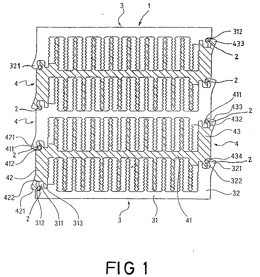
- Numeral 1 designates a heat sink overall, which is made of L-shaped Sub-profiles 3 and approximately Z-shaped further sub-profiles 4 can be produced or is produced. As can be seen from FIG. 2, this is one Heatsink 1 with the side that has the connections according to the corresponding machining on a semiconductor component 5 attached with a screw 6.
- the extruded sections 3 and 4 made of an aluminum alloy have web-like cooling fins parallel to one another in a known manner, the cooling surfaces form inside the individual cooling chambers.
- the two outer L-shaped partial profiles 3 face the profile wall 31 at the end a web strip 311 and immediately adjacent to the Grooves 312 and 313.
- On the other profile wall 32 is a front Groove 322 formed, the web strip 321 forming the groove wall initially, protrudes outwards as shown in FIG.
- the one with one Sub-profile connectable other sub-profiles 4 consist of the middle Profile wall 41 with the cooling fins formed vertically on both sides and the profile walls 42 and 43 arranged at the end Grooves 422 and 432 in turn on the end faces of the profile walls 42 and 43 provided, which from the outwardly projecting web strips 421 or 433 can be limited. These engage in these grooves 422 and 432, respectively Web strips 311 and 411 of adjacent partial profiles 3 and 4, respectively.
- Wires 2 made of pure aluminum are inserted into the grooves 312, 412 and 434 or inserted at the front.
- pressing takes place at the same time the very soft annealed wires 2.
- the plasticized Form wires 2 into the remaining column so that the profiles are completely liquid-tight at these connection points.
- This intimate liquid-tight connection increases the coefficient of friction, so that the profiles are connected to one another to a high degree in the longitudinal direction.
- the wires should be 1 - 3 mm thick, preferably 1 - 1.5 mm thick to have.
- a connecting side of a hollow chamber profile produced in this way 1 corresponding to Figure 2 forms a corresponding Machining the flat and smooth contact surface for one Semiconductor component indicated by the number 5.
- the corresponding grooves and the pressed Web strips each indicated with the numbers 321 ', 431' and 433 '.
Landscapes
- Engineering & Computer Science (AREA)
- Physics & Mathematics (AREA)
- Thermal Sciences (AREA)
- Mechanical Engineering (AREA)
- General Engineering & Computer Science (AREA)
- Cooling Or The Like Of Semiconductors Or Solid State Devices (AREA)
- Pressure Welding/Diffusion-Bonding (AREA)
- Forging (AREA)
- Body Structure For Vehicles (AREA)
- Bending Of Plates, Rods, And Pipes (AREA)
- Extrusion Of Metal (AREA)
Abstract
Vorgeschlagen wird ein Verfahren zur Herstellung von aus mehreren
stranggepreßten Teilprofilen 3, 4 aus einer Aluminiumlegierung bestehenden
Kühlkörpern 1, bei dem an den Teilprofilen 3, 4 ausgebildete Nuten
312, 412, 430 und Stegleisten 321, 421, 433 jeweils ineinander gesteckt
und in Querrichtung durch Druckbeaufschlagung verbunden werden. Dabei
werden jeweils nach außen abstehende bzw. vorstehende Nutwandungen
bzw. Stegleisten 321, 421, 433 eines Teilprofiles 3, 4 in entsprechenden
Nuten eines benachbarten Teilprofiles 3, 4 nach innen gebogen
und mit plastischer Verformung gedrückt zur formschlüssigen Verklammerung
der jeweiligen in die zugehörige Nut eingreifende Stegleisten. In die
Nuten 312, 412, 434 werden Drähte zwei aus reinst Aluminium oder einer
Aluminiumlegierung eingelegt und beim Verpressen der Stegleisten 321,
421, 433 in die zugehörigen Nuten 312, 412, 434 plastisch verformt. Die
Verbindungsstellen werden hier durch Flüssigkeit dicht. Die Verbindung
wird in Längsrichtung sicherer gestaltet.
Description
Aus der WO 97/27619 ist ein Verfahren zum Herstellen von aus mehreren Teilprofilen aus Metall bestehenden Kühlkörpern zum Anbau an Halbleiterbauelemente bekannt. Ebenso sind aus dieser Druckschrift Profile zur Herstellung solcher Kühlkörper und nach dem Verfahren hergestellte Kühlkörper zu entnehmen. Bei diesem bekannten Verfahren werden die entsprechend ausgebildeten Teilprofile, die insbesondere vorzugsweise als Strangpreßprofile hergestellt sind, mit an ihnen ausgebildeten Nuten und Stegleisten jeweils ineinander gesteckt und in Querrichtung durch Druckbeaufschlagung verbunden. Dabei werden nach außen abstehende bzw. vorstehende Nutwandungen bzw. Stegleisten der Teilprofile in entsprechende Nuten eines benachbarten Teilprofiles nach innen gebogen und mit plastischer Verformung gedrückt zur formschlüssigen Verklammerung der in die zugehörige Nut jeweils eingreifenden Stegleiste.WO 97/27619 describes a method for producing several Partial profiles made of metal heat sinks for mounting on semiconductor components known. This publication also contains profiles for Manufacture of such heat sinks and manufactured by the method Remove heat sink. In this known method, the appropriately trained sub-profiles, which are particularly preferred are produced as extruded profiles, with grooves formed on them and web strips are inserted into each other and in the transverse direction Pressurization connected. This will protrude outwards or protruding groove walls or web strips of the partial profiles in corresponding Grooves of an adjacent partial profile are bent inwards and pressed with plastic deformation for positive locking the web strip engaging in the associated groove.
Es zeigt sich in der Praxis, daß nach diesem bekannten Verfahren hergestellte Kühlkörper nur dann eine ausreichend innige Verbindung der Teilprofile aufweisen, wenn die Wandstärken der ineinandergreifenden Stegleisten und Nuten ausreichend groß sind, wobei hohe Druckkräfte zu ihrer Verformung notwendig sind. Es zeigt sich außerdem, daß die entsprechenden Verbindungsstellen nicht flüssigkeitsdicht sind, so daß die Verwendung solcher Kühlkörper nur für die Durchführung von gasförmigen Kühlmitteln möglich ist.It has been shown in practice that manufactured by this known method Heat sink only then a sufficiently intimate connection of the partial profiles if the wall thicknesses of the interlocking Web strips and grooves are sufficiently large, with high compressive forces their deformation are necessary. It also shows that the corresponding Junctions are not liquid-tight, so that the Use of such heat sinks only for the implementation of gaseous ones Coolants is possible.
Die Aufgabe der Erfindung besteht darin, ein Verfahren zur Herstellung solcher bekannter Kühlkörper aus Teilprofilen vorzuschlagen, mit dem eine flüssigkeitsdichte Verbindung der Teilprofile erreicht wird und eine ausreichend stabile Verbindung der Teilprofile bei möglichst geringen Wandstärken der Verbindungsabschnitte erzielbar ist.The object of the invention is a method for the production propose such known heat sink from sub-profiles, with the a liquid-tight connection of the partial profiles is achieved and a sufficiently stable connection of the partial profiles with the lowest possible Wall thicknesses of the connecting sections can be achieved.
Gelöst wird die Erfindungsaufgabe mit dem Verfahren mit den Merkmalen
des Anspruchs 1. Durch das Einlegen von Drähten aus Reinstaluminium
in den entsprechenden Nuten und das nachträgliche Verpressen dieser
drähte zusammen mit den einzupressenden Stegleisten werden jeweils
die Drähte plastisch verformt und fließen weitgehend ausfüllend in die
noch vorhandenen Spalträume auf.The invention task is solved with the method with the features
of
Der plastisch verformte Draht haftet durch Kaltschweißung fest an der Oberfläche der Profile und bewirkt dadurch eine festhaftende und dichtende Verbindung. Hierdurch erfolgt eine flüssigkeitsdichte Verbindung der Teilprofile in Profillängsrichtung von hoher Qualität, wodurch auch das gesamte Kühlprofil-Bauteil wesentlicher stabiler wird.The plastically deformed wire adheres firmly to the cold weld Surface of the profiles and thereby creates a firmly adhering and sealing Connection. This results in a liquid-tight connection of the Partial profiles in the longitudinal direction of high quality, which also entire cooling profile component becomes much more stable.
Die verhältnismäßig hohen Umformkräfte durch Roll- oder Druckwerkzeuge können verringert werden, da der einliegende weiche Draht eine leichtere plastische Verformung ermöglicht. Dies hat aber auch zur Folge, daß die Profile, die auch der Abstützung der Verformungskräfte dienen, leichter gebaut werden können, was neben der Gewichtseinsparung auch für die Wärmeübertragung von besonderer Bedeutung sein kann.The relatively high forming forces caused by rolling or pressure tools can be reduced because the inserted soft wire is a lighter plastic deformation enables. But this also has the consequence that the profiles, which also serve to support the deformation forces, are lighter can be built, which in addition to saving weight also for heat transfer can be of particular importance.
Vorzugsweise werden weichgeglühte Aluminiumdrähte mit einem Reinheitsgehalt von 99,9 % verwendet. Diese Drähte können einen Durchmesser von 1 - 1,5 mm besitzen und lassen sich dabei in den entstehenden Verbindungsspalten noch verpressen, ohne daß Drahtmaterial nach außen austritt.Soft annealed aluminum wires with a purity content are preferred used by 99.9%. These wires can have a diameter 1 - 1.5 mm and can be created in the resulting Press the connection gaps without wire material exits outside.
Insgesamt zeigt es sich, daß die innigen Verbindungen der nach dem erfindungsgemäßen Verfahren hergestellten Kühlprofile im Bereich der Verbindungsstellen bessere Wärmedurchgangswerte aufweisen. Die hohen Preßkräfte bei der Ausbildung der Verbindungen lassen sich reduzieren.Overall, it turns out that the intimate compounds of those according to the invention Process produced cooling profiles in the area of the connection points have better heat transfer values. The high Pressing forces in the formation of the connections can be reduced.
Anhand eines prinzipiell abgebildeten Ausführungsbeispieles wird das erfindungsgemäße Verfahren erläutert. Es zeigen:
- Fig. 1
- einen Querschnitt durch die Montageanordnung mehrerer Teilprofile vor der Verpressung der Verbindungsstellen und
- Fig. 2
- einen entsprechenden Querschnitt der Anordnung in
Figur 1 nach der Verpressung der nach außen abstehenden Stegleisten in die entsprechenden zugehörigen Nuten.
- Fig. 1
- a cross section through the assembly arrangement of several partial profiles before the pressing of the joints and
- Fig. 2
- a corresponding cross section of the arrangement in Figure 1 after pressing the outwardly projecting web strips into the corresponding associated grooves.
Mit der Ziffer 1 ist insgesamt ein Kühlkörper bezeichnet, der aus L-förmigen
Teilprofilen 3 und etwa Z-förmigen weiteren Teilprofilen 4 herstellbar
bzw. hergestellt ist. Wie aus Figur 2 ersichtlich ist ein solcher
Kühlkörper 1 mit der Seite, die die Verbindungen aufweist nach entsprechender
spanabhebender Bearbeitung an einem Halbleiterbauelement 5
mit einer Schraubverbindung 6 befestigt.Numeral 1 designates a heat sink overall, which is made of L-
Die stranggepreßten Teilprofile 3 und 4 aus einer Aluminiumlegierung
weisen in bekannter Weise zueinander parallele stegartige Kühlrippen auf,
die Kühlflächen bilden im Inneren der einzelnen Kühlkammern.The
Die beiden außen liegenden L-förmigen Teilprofile 3 weisen an der Profilwand
31 am Ende eine Stegleiste 311 und unmittelbar benachbart die
Nuten 312 und 313 auf. An der anderen Profilwand 32 ist stirnseitig eine
Nut 322 ausgebildet, deren die Nutwand bildende Stegleiste 321 zunächst,
wie in Figur 1 gezeigt, nach außen absteht. Die mit einem solchen
Teilprofil verbindbaren anderen Teilprofile 4 bestehen aus der mittleren
Profilwand 41 mit den senkrecht an beiden Seiten angeformten Kühlrippen
und den endseitig angeordneten Profilwänden 42 und 43. Dabei sind
stirnseitig an den Profilwänden 42 und 43 wiederum Nuten 422 und 432
vorgesehen, die von den nach außen abstehenden Stegleisten 421 bzw.
433 begrenzt werden. In diese Nuten 422 und 432 greifen jeweils die
Stegleisten 311 und 411 benachbarter Teilprofile 3 bzw. 4 ein.The two outer L-shaped
In die Nuten 312, 412 und 434 werden Drähte 2 aus Reinstaluminium eingelegt
bzw. stirnseitig eingeschoben. Durch Verbiegen bzw. Verpressen
der nach außen abstehenden Stegleisten 321 und 421 bzw. 433 in die
Nuten 312, 412 bzw. 434 der benachbarten Teilprofile, beispielsweise
durch Rollen oder Prägevorgänge, erfolgt gleichzeitig eine Verpressung
der sehr weichen geglühten Drähte 2. Es erfolgt eine endgültige und innige
Verklammerung der Teilprofile 3 und 4 miteinander, wobei die plastifizierten
Drähte 2 sich in die verbleibende Spalte formen, so daß die Profile
an diesen Verbindungsstellen vollständig flüssigkeitsdicht sind. Diese innige
flüssigkeitsdichte Verbindung erhöht die Reibwerte, so daß die Profile
in hohem Maße in Längsrichtung schubfest miteinander verbunden sind.
Die Drähte sollten eine Stärke von 1 - 3 mm, vorzugsweise 1 - 1,5 mm
haben.
Eine Verbindungsseite eines auf diese Weise hergestellten Hohlkammerprofiles
1 entsprechend Figur 2 bildet nach einer entsprechenden
spanabhebenden Bearbeitung die ebene und glatte Kontaktfläche für ein
mit der Ziffer 5 angedeutetes Halbleiterbauelement. In dieser Darstellung
des fertigen Produktes sind die entsprechenden Nuten und die verpreßten
Stegleisten jeweils mit den Ziffern 321', 431' und 433' angedeutet.A connecting side of a hollow chamber profile produced in this
Claims (3)
Applications Claiming Priority (2)
| Application Number | Priority Date | Filing Date | Title |
|---|---|---|---|
| DE10141988 | 2001-08-28 | ||
| DE10141988A DE10141988C1 (en) | 2001-08-28 | 2001-08-28 | Modular heat sink manufacturing method uses transverse pressure for clamping projection of one extruded profile in channel of adjacent extruded profile by plastic deformation of Al wire |
Publications (2)
| Publication Number | Publication Date |
|---|---|
| EP1291908A2 true EP1291908A2 (en) | 2003-03-12 |
| EP1291908A3 EP1291908A3 (en) | 2007-03-14 |
Family
ID=7696786
Family Applications (1)
| Application Number | Title | Priority Date | Filing Date |
|---|---|---|---|
| EP02015462A Withdrawn EP1291908A3 (en) | 2001-08-28 | 2002-07-12 | Method of fabrication of heat sinks |
Country Status (3)
| Country | Link |
|---|---|
| US (1) | US6671957B2 (en) |
| EP (1) | EP1291908A3 (en) |
| DE (1) | DE10141988C1 (en) |
Families Citing this family (8)
| Publication number | Priority date | Publication date | Assignee | Title |
|---|---|---|---|---|
| US6868899B1 (en) * | 2003-08-25 | 2005-03-22 | Hewlett-Packard Development Company, L.P. | Variable height thermal interface |
| CN2701072Y (en) * | 2004-04-29 | 2005-05-18 | 鸿富锦精密工业(深圳)有限公司 | Heat sink |
| US7259965B2 (en) * | 2005-04-07 | 2007-08-21 | Intel Corporation | Integrated circuit coolant microchannel assembly with targeted channel configuration |
| US20070223196A1 (en) * | 2006-03-22 | 2007-09-27 | Ming-Sho Kuo | Composite heatsink plate assembly |
| US20090065174A1 (en) * | 2007-09-10 | 2009-03-12 | Yu-Jen Lai | Heat sink for an electrical device and method of manufacturing the same |
| SE535091C2 (en) | 2010-05-28 | 2012-04-10 | Webra Technology Ab | A cooling device and a method of manufacturing a cooling device |
| WO2019188483A1 (en) | 2018-03-27 | 2019-10-03 | 三菱電機株式会社 | Cooling device, cooling device with lid, and case with cooling device |
| DE102019107280B4 (en) * | 2019-03-21 | 2026-01-29 | apt Extrusions GmbH & Co. KG | Cooling device for cooling a third-party object to be cooled |
Family Cites Families (13)
| Publication number | Priority date | Publication date | Assignee | Title |
|---|---|---|---|---|
| US3735465A (en) * | 1969-01-21 | 1973-05-29 | Airco Inc | Assembling apparatus for rolling and clamping a part to a tubular member |
| DE3518310A1 (en) * | 1985-05-22 | 1986-11-27 | Aluminium-Walzwerke Singen Gmbh, 7700 Singen | REFRIGERATOR BODY FOR SEMICONDUCTOR COMPONENTS AND METHOD FOR THE PRODUCTION THEREOF |
| US5042257A (en) * | 1989-05-01 | 1991-08-27 | Kendrick Julia S | Double extruded heat sink |
| SE467070B (en) * | 1990-01-24 | 1992-05-18 | Pavel Cech | DEVICE FOR THERMOELECTRIC COOLERS / HEATERS |
| JP2549817Y2 (en) * | 1991-01-31 | 1997-10-08 | 株式会社椿本チエイン | Hydraulic tensioner with integrated mounting plate and gasket |
| DE9315056U1 (en) * | 1993-10-05 | 1993-12-16 | Julius & August Erbslöh GmbH & Co, 42553 Velbert | Heatsinks for semiconductor devices |
| TW265430B (en) * | 1994-06-30 | 1995-12-11 | Intel Corp | Ducted opposing bonded fin heat sink blower multi-microprocessor cooling system |
| US5641713A (en) * | 1995-03-23 | 1997-06-24 | Texas Instruments Incorporated | Process for forming a room temperature seal between a base cavity and a lid using an organic sealant and a metal seal ring |
| US5689873A (en) * | 1996-01-11 | 1997-11-25 | Allfast Fastening Systems, Inc. | Tacking fastener |
| DE29712058U1 (en) | 1996-01-27 | 1998-04-02 | Bayer, Joachim, 51503 Rösrath | Heat sinks for mounting on semiconductor components and partial profiles for the production of such heat sinks |
| ATE223265T1 (en) * | 1996-06-26 | 2002-09-15 | Showa Denko Kk | METHOD FOR PRODUCING FLAT TUBES FOR HEAT EXCHANGERS |
| DE29710397U1 (en) * | 1997-06-14 | 1997-08-14 | Bayer, Joachim, 51503 Rösrath | Hollow chamber profile heat sink for semiconductor components |
| DE29721186U1 (en) * | 1997-11-29 | 1998-01-22 | MDM Diels GmbH, 58540 Meinerzhagen | Heatsink for mounting on semiconductor components |
-
2001
- 2001-08-28 DE DE10141988A patent/DE10141988C1/en not_active Expired - Fee Related
-
2002
- 2002-07-12 EP EP02015462A patent/EP1291908A3/en not_active Withdrawn
- 2002-08-21 US US10/224,935 patent/US6671957B2/en not_active Expired - Fee Related
Also Published As
| Publication number | Publication date |
|---|---|
| US6671957B2 (en) | 2004-01-06 |
| US20030041456A1 (en) | 2003-03-06 |
| EP1291908A3 (en) | 2007-03-14 |
| DE10141988C1 (en) | 2003-01-09 |
Similar Documents
| Publication | Publication Date | Title |
|---|---|---|
| DE69201775T2 (en) | Inner rib and process for its manufacture. | |
| DE69430096T2 (en) | Method and apparatus for producing high-density heat sinks | |
| EP0206980B1 (en) | Heat sink for semiconductor devices and method for manufacturing the same | |
| DE3107010C2 (en) | Metal cooler for cooling a fluid flowing through under high pressure with air | |
| DE3752324T2 (en) | capacitor | |
| DE3615300C2 (en) | ||
| EP0733871B1 (en) | Heat transfer tube for a heat exchanger | |
| DE10200019B4 (en) | Heat sink for semiconductor devices, method for its production and tool for carrying out the method | |
| EP0956587A2 (en) | Method of manufacturing cooling devices made up of several metal shaped-section elements for mounting on semiconductor components, shaped-section elements for use in the manufacture of such cooling devices and cooling devices manufactured by the method | |
| EP1179167A1 (en) | Heat exchanger and method for producing a heat exchanger | |
| DE10141988C1 (en) | Modular heat sink manufacturing method uses transverse pressure for clamping projection of one extruded profile in channel of adjacent extruded profile by plastic deformation of Al wire | |
| DE69634308T2 (en) | METHOD FOR CONTINUOUS PRODUCTION OF PROFILED PARTS AND DEVICE FOR CARRYING OUT THE METHOD | |
| DE29507286U1 (en) | Heat sink for semiconductor components or the like. equipment | |
| EP0734062A2 (en) | Heat sink for semiconductor device or similar | |
| EP1227291A2 (en) | Heat exchanger and method of production | |
| DE2803365A1 (en) | METHOD AND APPARATUS FOR MANUFACTURING CROSS-FIBED PIPES | |
| DE10229532B4 (en) | Cooling device for semiconductor devices | |
| EP0795905A2 (en) | Heat sink for semi-conductor devices or similar arrangements | |
| DE29601776U1 (en) | Heat sink for semiconductor components or the like. | |
| DE69611489T2 (en) | Radiation fins and process for their manufacture | |
| DE4133340C2 (en) | Capacitor cup housing with predetermined bursting area as well as method and tool for its production | |
| DE19841911A1 (en) | Heat sink device for semiconductor elements or electric motor has extruded lightweight metal base profile provided with projecting spaced cooling ribs | |
| DE19846347A1 (en) | Heat exchanger of aluminum or aluminum alloy is composed in layered structure of extruded profile tubes of rectangular configuration with several adjacent channels separated by longitudinal ribs | |
| DE19836314A1 (en) | Heatsink attachment for semiconductor components, with cooler profiles extruded from special aluminum alloy has a bent semicircular shape | |
| DE102006040519B4 (en) | Method for producing a busbar |
Legal Events
| Date | Code | Title | Description |
|---|---|---|---|
| PUAI | Public reference made under article 153(3) epc to a published international application that has entered the european phase |
Free format text: ORIGINAL CODE: 0009012 |
|
| AK | Designated contracting states |
Kind code of ref document: A2 Designated state(s): AT BE BG CH CY CZ DE DK EE ES FI FR GB GR IE IT LI LU MC NL PT SE SK TR Designated state(s): AT BE BG CH CY CZ DE DK EE ES FI FR GB GR IE IT LI LU MC NL PT SE SK TR |
|
| AX | Request for extension of the european patent |
Extension state: AL LT LV MK RO SI |
|
| PUAL | Search report despatched |
Free format text: ORIGINAL CODE: 0009013 |
|
| AK | Designated contracting states |
Kind code of ref document: A3 Designated state(s): AT BE BG CH CY CZ DE DK EE ES FI FR GB GR IE IT LI LU MC NL PT SE SK TR |
|
| AX | Request for extension of the european patent |
Extension state: AL LT LV MK RO SI |
|
| AKX | Designation fees paid | ||
| STAA | Information on the status of an ep patent application or granted ep patent |
Free format text: STATUS: THE APPLICATION IS DEEMED TO BE WITHDRAWN |
|
| 18D | Application deemed to be withdrawn |
Effective date: 20070915 |
|
| REG | Reference to a national code |
Ref country code: DE Ref legal event code: 8566 |