EP1291677A2 - Method for stitching partial radiation images to reconstruct a full image - Google Patents
Method for stitching partial radiation images to reconstruct a full image Download PDFInfo
- Publication number
- EP1291677A2 EP1291677A2 EP02078561A EP02078561A EP1291677A2 EP 1291677 A2 EP1291677 A2 EP 1291677A2 EP 02078561 A EP02078561 A EP 02078561A EP 02078561 A EP02078561 A EP 02078561A EP 1291677 A2 EP1291677 A2 EP 1291677A2
- Authority
- EP
- European Patent Office
- Prior art keywords
- image
- screen
- images
- pair
- digital images
- Prior art date
- Legal status (The legal status is an assumption and is not a legal conclusion. Google has not performed a legal analysis and makes no representation as to the accuracy of the status listed.)
- Withdrawn
Links
Images





Classifications
-
- G—PHYSICS
- G01—MEASURING; TESTING
- G01T—MEASUREMENT OF NUCLEAR OR X-RADIATION
- G01T1/00—Measuring X-radiation, gamma radiation, corpuscular radiation, or cosmic radiation
- G01T1/16—Measuring radiation intensity
- G01T1/20—Measuring radiation intensity with scintillation detectors
- G01T1/2012—Measuring radiation intensity with scintillation detectors using stimulable phosphors, e.g. stimulable phosphor sheets
- G01T1/2014—Reading out of stimulable sheets, e.g. latent image
-
- A—HUMAN NECESSITIES
- A61—MEDICAL OR VETERINARY SCIENCE; HYGIENE
- A61B—DIAGNOSIS; SURGERY; IDENTIFICATION
- A61B6/00—Apparatus or devices for radiation diagnosis; Apparatus or devices for radiation diagnosis combined with radiation therapy equipment
- A61B6/52—Devices using data or image processing specially adapted for radiation diagnosis
- A61B6/5211—Devices using data or image processing specially adapted for radiation diagnosis involving processing of medical diagnostic data
- A61B6/5229—Devices using data or image processing specially adapted for radiation diagnosis involving processing of medical diagnostic data combining image data of a patient, e.g. combining a functional image with an anatomical image
- A61B6/5235—Devices using data or image processing specially adapted for radiation diagnosis involving processing of medical diagnostic data combining image data of a patient, e.g. combining a functional image with an anatomical image combining images from the same or different ionising radiation imaging techniques, e.g. PET and CT
- A61B6/5241—Devices using data or image processing specially adapted for radiation diagnosis involving processing of medical diagnostic data combining image data of a patient, e.g. combining a functional image with an anatomical image combining images from the same or different ionising radiation imaging techniques, e.g. PET and CT combining overlapping images of the same imaging modality, e.g. by stitching
Definitions
- This invention relates in general to digital radiography, and in particular to the imaging of a long human body part, such as the spine or legs, using a storage phosphor-based computed radiography system.
- the cassettes can be in the alternating (Fig.1A), staircase-wise (Fig.1B), or oblique (Fig.1C) arrangement.
- Fig.1A alternating
- Fig.1B staircase-wise
- Fig.1C oblique
- the drawback of this approach is that the metallic frames of the front (closer to the x-ray source) cassettes impose shadows in the image recorded in the back cassettes. The shadows are not removable and therefore may hinder diagnostic interpretation of the acquired images.
- European Patent EP0866342A1 presents a method that is based on partially overlapping a plurality of storage phosphor screens for extended imaging coverage.
- the screens can also be configured in an alternating (Fig.1D), staircase-wise (Fig.1E), or oblique (Fig. 1F) overlapping arrangement.
- the screens can be contained in a single, extended length cassette for convenience of use.
- This approach overcomes the drawback of the cassette stacking method because there are no cassette metallic frames present in the x-ray path.
- this method requires that the storage phosphor screens be removed from the cassettes before imaging, and to be placed back into the cassettes in a darkroom after the x-ray exposure, which is cumbersome in the clinical environment.
- European Patent EP0919858A1 proposes a method that utilizes a pattern of reference markers that impose shadows simultaneously with the diagnostic image in each of the acquired sub-images. After the reference markers are identified in each subimage, the image distortion is corrected based on the known marker locations. Translation and rotation displacements between the sub-images are also computed using the known marker locations. Once the geometric compensation processing is completed, the composite full image is reconstructed.
- the drawback of this method is that a precisely fabricated pattern of reference markers must be imaged simultaneously with the patient in order to achieve precise geometric registration of the sub-images. The shadow of the reference markers may obscure diagnostically important information in the stitched image.
- a method of forming a composite digital image comprising:
- the invention has the following advantages.
- Figs. 1A - 1G are diagrammatic views of several multiple cassette-screen arrangements.
- Figs. 1A - 1C shows a plurality of storage phosphor cassettes, with each cassette containing one storage phosphor screen, arranged in alternating, staircase-wise, and oblique positions, respectively.
- the storage phosphor screens are represented as solid vertical lines inside the cassettes.
- Figs. 1D - 1F shows a plurality of storage phosphor screens arranged in alternating, staircase-wise, and oblique positions, respectively.
- the screens can be contained within a single, extended length cassette.
- Fig. 1G shows a configuration consisting of a set of storage phosphor screens/cassettes that are placed in an alternating arrangement with the screens placed in front of the cassettes (closer to x-ray source).
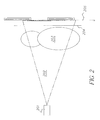
- Fig. 2 is a diagrammatic view showing the method for image acquisition using the alternating phosphor screen/cassette configuration shown in Fig. 1G as an example. Any of the other configurations shown in Fig. 1 can also be used for acquiring the images.
- Fig. 3A is a diagrammatic view showing three sub-images acquired using any of the configurations shown in Fig. 1.
- the middle image 302 is recorded on a storage phosphor screen (either the screen itself or the screen within a cassette) that is placed closer to the x-ray source.
- the top image 301 and the bottom image 303 are recorded on two storage phosphor screens (either the screen itself or the screen within a cassette) that are placed behind the middle screen.
- the shadow of the middle screen top edge is recorded in image 301, and the shadow of the bottom edge is recorded in image 303.
- Fig. 3B is a modification of the middle image of Fig. 3A.
- Figs. 4A and 4B are diagrammatic views illustrating the definitions of the front screen, back screen, front screen overlap edge, and back screen overlap edge.
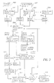
- Fig. 5 is a flow diagram showing the image processing steps for automatic formation of a composite image from a plurality of images according to the present invention.
- Fig. 6 is a diagrammatic view illustrating the major image processing steps that are used to automatically find the locations and orientations of the screen overlap edges in both the front and the back images, and for finding the location and orientation of the shadow of the front screen overlap edge in the back image.
- Fig. 7 is a diagrammatic view illustrating the major image processing steps that are used for finding the horizontal displacement between the front and back images by image-correlation.
- Figs. 8A and 8B are diagrammatic views showing examples of composite stitched images from two screens and three screens, respectively.
- the present invention relates to the radiographic imaging of an elongated object such as the full spine, e.g., for diagnosing scoliosis, or leg of a human subject.
- a plurality of sub-images is obtained, each of which bears a partial image of the elongated object.
- the phosphor screens are the fundamental imaging recording devices, no matter whether the screens are packaged within individual cassette or not, the term "storage phosphor screen”, “phosphor screen”, or “screen” is used hereinafter to represent either the phosphor screen itself or the phosphor screen that is conveyed inside a cassette. Therefore the different scenarios in Fig. 1 are reduced to alternating, staircase-wise, and oblique arrangements of overlapping phosphor screens, with the exception that the distance between the screen planes can vary for each scenario depending on if the screen(s) is contained inside the cassette or not.
- Fig. 2 shows the process for conducting an x-ray exposure.
- the patient (element 203) is positioned between the x-ray source (element 201) and a plurality of screens (element 205). Any of the screen arrangement methods shown in Figs. 1A-1G can be used for imaging.
- An optional anti-scatter grid (element 204) can be placed between the patient and the screens.
- the grid can be either a stationary type or reciprocating type.
- the x-rays can be collimated to minimize the radiation to the non-diagnostically relevant patient anatomy.
- the image of the patient is recorded by the plurality of screens as latent radiographic signals. Each screen captures only a portion of the image of the patient.
- the screens are fed into a CR reader and the latent radiographic signals are converted to electronic images.
- Fig. 3A shows an example for the case where three storage phosphor screens are exposed.
- the two phosphor screens that capture the first image (element 301) and the third image (element 303) are placed behind the screen that captures the second image (element 302).
- the first screen 301 and the second screen 302 partially overlap, and the second screen 302 is not totally opaque to the incident x-rays, the first screen 301 still captures the image of the patient in the screen overlap region (element 307).
- the signal-to-noise ratio of the image captured on the first screen 301 in the overlap region will be relatively lower because of the x-ray attenuation caused by the second screen 302.
- the top edge of the second screen 302 also imposes a distinct shadow in the first image, as indicated by element 305.
- the bottom edge of the second screen 302 imposes a shadow in the third image, as indicated by element 306 in screen 303.
- the boundaries between the collimated and non-collimated exposure regions are indicated by element 304.
- any two consecutive screens is equivalent for the screen configurations shown in Figs. 1A-1G.
- the screens partially overlap and one screen is positioned closer to the x-ray source.
- the term "front screen” will be used to refer to the screen that is positioned closer to the x-ray source, and the term “front image” will be used to refer to the image captured with the front screen.
- the terms "back screen” and “back image” are used to refer to the screen that is positioned further from the x-ray source and "back image” will refer to the image captured with the "back screen”.
- the screens can be divided into N-1 screen pairs, each of which consists of two consecutive screens - one front screen and one back screen.
- one screen can be the front screen in one "screen pair", and can also be the back or the front screen in the next screen pair.
- the problem of reconstructing a composite full image consists of stitching the front and back images acquired with a screen pair. Once the first pair of images is stitched, the resultant composite image is grouped with the next consecutive image into a new front/back image pair. The same stitching method is used again and a new larger composite image is created. This process is repeated until all the images are stitched together.
- the term "veuical” is used to mean the direction in which the phosphor screens are stacked and the term “horizontal” is used to mean the direction perpendicular to the "vertical”. It will be understood that the screens can be oriented in any direction during x-ray exposure.
- Figs. 4A and 4B illustrate additional terminology used in this invention description, where the front and back screen overlap edges are indicated by elements 406 and 407.
- 1 is comprised of the following steps: (1) selection of a first pair of consecutive images, which consist of a front image and a back image, (2) demagnification of image pixels if applicable based on the distance between the x-ray source and the phosphor screens, (3) determination of the rotational displacement and the vertical displacement between the front and back images by matching the front screen overlap edge in the front image to its shadow in the back image, (4) image orientation correction if applicable based on the rotational displacement, (5) determination of the horizontal displacement between the front and back images by correlating the image information in the overlapping screen regions, and (6) stitching the front and the back images together to create a larger composite image along the front screen overlap edge based on the horizontal and vertical displacements, and (7) repeat steps 2-6 with the larger composite image and the next consecutive image until all the images are stitched together.
- the CR reader should be capable of over-scanning the front phosphor screen beyond the overlap edge.
- the top and bottom edges of the phosphor screen are over-scanned, the resultant image is indicated by element 310, and the top and bottom edges are completely visible (elements 311 and 312).
- the location and orientation of edges 311 and 312 will be compared to the corresponding shadows (elements 305 and 306 in Fig. 3A), based on how the relative orientation and vertical displacement between the first and second images as well as the second and third images are computed.
- Fig. 5 is a flowchart that describes the key steps of this invention using a CR reader that overscans both the top and bottom edges of all the phosphor screens. It is understood that many variations can be derived based on the spirit of this invention.
- a virtual reference detector plane is defined and all the captured images are normalized to this plane.
- This reference detector plane can be defined anywhere in the x-ray path, such as the anti-scatter grid surface plane.
- the parameters x and y are image pixel coordinates in the vertical and horizontal axes, respectively; x' and y' are the new image pixel coordinates, respectively g is a constant; and D 0 and D respectively are the distances from the x-ray source to the reference detector plane and the distance from the x-ray source to the physical storage phosphor screen that captures the image.
- the reference detector plane (RDP) coincides with the plane of the front storage phosphors
- the back storage phosphor plane (SPP) coincides with the plane of back storage phosphors.
- the distance D 0 and D are the same for the front storage phosphor plane and different for the back storage phosphor plane.
- x' g(x) ⁇ x
- y' g(x) ⁇ y
- g(x) ((D b - D t ) ⁇ (x - x min ) / (x max - x min ) + D t ) / D 0
- D t and D b are the distances from the x-ray source to the top and the bottom of screen, respectively
- x min and x max are the minimum and maximum image pixel coordinate in the vertical axis. Equation 2 ensures that each image pixel is remapped to the reference detector plane based on its physical distance from the x-ray source.
- the amount of computation for image demagnification can be reduced nearly in half for the screen setups in Fig. 1A, 1D, and 1G by defining the reference detector plane to be located at the same position as the screens that are positioned closer to the x-ray source. Using this reference detector plane location causes the g factor in equation 1 to have a value of 1, i.e., no demagnification is required for the front images. This demagnification step can be totally eliminated when the x-ray source to the phosphor screens becomes much larger than the distance between the screens, as the distortion introduced by the magnification factor is negligible.
- the next step Element 509 is to identify the front and back images acquired with two consecutive screens.
- the screen overlap edges must be located correspondingly from the front and back images (element 510, 511).
- the shadow of the front screen overlap edge is then detected in the back image (element 512).
- These steps are further illustrated in Fig. 6.
- the pixel values in the image region that is beyond the screen overlap edge reflect the baseline noise level of the CR reader. This is because there is no signal contribution from the phosphor screen. Consequently, the pixel values in these regions are relatively low in comparison to those in the normally exposed image regions, therefore there is an abrupt pixel value decrement/discontinuity across the screen overlap edge in the image.
- This pixel value discontinuity is used to detect the location and orientation of the screen overlap edges, which can be accomplished in many ways.
- the detection is carried out by (1) computing all the significant edge transition pixels in the proximity of the screen overlap edge, and (2) performing line delineation of the candidate transition pixels of the screen overlap edge.
- Fig. 6 describes the preferred embodiment of the detection process.
- a narrow band 602 is extracted from the end of the front image 600.
- the orientation of the screen ending edge 601 can have a variation of several degrees in the acquired image from one scan to the next scan. Therefore, the size of the narrow band must be large enough such that the entire screen ending edge can be reliably extracted.
- the size of the narrow band should be approximately 200 x 2,048 pixels.
- the one-dimensional derivative of the image is computed in the vertical direction.
- a one-dimensional derivative operator such as [-1,0,1], [-1,0,0,0,1], or [-1,0,0,0,0,] etc., is preferred because the pixel value discontinuity only occurs across the edge direction, which is always nearly horizontal, and because of the computational efficiency advantages.
- a predefined threshold is used to select only those candidate edge transition pixels that are of greater magnitude and of falling slope.
- Element 603 shows the results from this step.
- a linear function is fitted to the candidate edge pixels and the best fitting parameters are obtained when the least square error is reached.
- Element 604 shows the fitted linear function overlaid on top of the edge transition pixels.
- this process is conducted for the back image 610, except rising edge transition pixels are searched instead inside a narrow band 614 at the beginning of the back image.
- Element 616 shows the fitted linear function overlaid on top of the edge transition pixels.
- the screen overlap edge location is successfully found in the front image, it is compared with its shadow in the back image for image registration.
- an approach similar to element 511 is used. This is possible because the pixel values in the back image also undergo a strong signal intensity decrement in the screen overlap region due to the high attenuation of the incident x-rays by the front screen during the x-ray exposure.
- the location of the narrow band needs to be defined in the back image. This can be calculated based on the size of the overlap regions ( S in mm), which is a priori , the image pixel size ( psize in mm), and the average location of the identified back screen overlap edge.
- parameters k f and k should be equal because they both represent the orientation of the front screen overlap edge. However, they may differ by as much as several degrees in practice for several reasons such as misalignment between the two phosphor screens during the x-ray exposure or screen positioning variations in the CR reader during the readout process.
- the deviation between k f and k represents the orientation misalignment between the front and back images.
- this misalignment must be corrected. However, the correction can be ignored if the misalignment is fairly small. For example, in the case when it only generates a maximum of several pixel gap i.e., k f - k x y max ⁇ 3 where y max is the maximum image pixel coordinate in the horizontal direction.
- Element 513 (Fig. 5) represents the process for calculating the rotational angle and the calculation of the vertical displacement.
- Element 514 (Fig. 5) represents the image rotation operation.
- the parameters that are used for aligning the front and back images e.g., k a , k b , k, a a , a b , and a , are calculated before image rotation, they must be transformed accordingly to reflect their new values in the rotated image(s).
- the symbols k a , k b , k, a a , a b , and a will be used to represent the new transformed values.
- the location of the screen overlap region in the back image can be defined.
- the screen overlap region in the back image is located between the back screen overlap edge and the shadow of the front screen overlap edge.
- overlap_offset f x max - ( k a ⁇ y c + a a ) - overlap_size .
- the image content recorded in the overlap regions are the same except for some horizontal displacement, y_offset , between the corresponding pixels.
- the ⁇ value at which c( ⁇ ) reaches a maximum is the optimal value for y_offset.
- Fig. 7 describes the preferred implementation of this operation.
- First the overlap region 702 and 703 are extracted from the front and back images respectively.
- Second element 704 is obtained by extracting a portion of 702, then is correlated with 703 to create the correlation function c( ⁇ ) , 706. Similar results can be achieved by correlating a portion of 703 with 702.
- Third the maximum of function c( ⁇ ) is searched and the corresponding value of ⁇ is identified as y_offset , 707. Because the edge information in 702 and 703, including skin line, tissue boundaries, bone edges, collimation boundaries (element 304 in Fig.
- the low frequency content is removed from 702 and 703 in order to improve the correlation robustness.
- the presence of the collimation shadow (element 304) helps improve the algorithm robustness in finding y_offset Therefore, it is recommended to use collimation during the x-ray exposure.
- the correlation function is smooth, but if a stationary grid is used during the x-ray exposure, it imposes a periodic line pattern artifact in the acquired images. This artifact is particularly dominant when the grid is orientated in the vertical direction, and can correlate with itself, causing periodic small spikes to be introduced on top of the background correlation function. This artifact will negatively impact the accuracy in determining the location of the true function maximum. To address this issue, low-pass filtering of the correlation function is used before searching for the maximum. The process described in this paragraph is represented by element 516 (Fig. 5).
- the back image is stitched to the front image.
- Each pixel of the front image is copied to the stitched image buffer except those pixels that are beyond the screen overlap edge line.
- Each pixel in the back image is copied to the stitched image buffer with an displacement defined by x_offset and y_offset except those pixels before the shadow of the front screen overlap edge.
- Fig. 8A The process conducted in this paragraph is represented by element 517 (Fig. 5).
- Fig. 8B shows a stitched image acquired with three screens. The composite full image is then outputted (Element 519 - Fig. 5).
- the invention may be applied to the stitching together of any number of over-lapped images produced by radiographic techniques.
- the invention would also be applicable to digital images resulting from overlapping conventional radiographic film images that have been digitized.
Landscapes
- Health & Medical Sciences (AREA)
- Life Sciences & Earth Sciences (AREA)
- Engineering & Computer Science (AREA)
- Medical Informatics (AREA)
- Molecular Biology (AREA)
- Physics & Mathematics (AREA)
- High Energy & Nuclear Physics (AREA)
- Biomedical Technology (AREA)
- Animal Behavior & Ethology (AREA)
- Optics & Photonics (AREA)
- Pathology (AREA)
- Radiology & Medical Imaging (AREA)
- Biophysics (AREA)
- Heart & Thoracic Surgery (AREA)
- Computer Vision & Pattern Recognition (AREA)
- Surgery (AREA)
- Nuclear Medicine, Radiotherapy & Molecular Imaging (AREA)
- General Health & Medical Sciences (AREA)
- Public Health (AREA)
- Veterinary Medicine (AREA)
- General Physics & Mathematics (AREA)
- Spectroscopy & Molecular Physics (AREA)
- Image Processing (AREA)
- Apparatus For Radiation Diagnosis (AREA)
- Facsimile Scanning Arrangements (AREA)
- Image Analysis (AREA)
- Image Input (AREA)
Abstract
Description
Claims (10)
- A method of forming a composite digital image comprising:providing 1-N digital images formed from 1-N contiguous segments of a larger radiographic image recorded in 1-N overlapping storage phosphor screens wherein N is equal to or greater than 2 and wherein the image content in the overlapped region of contiguous images is the same, and the end edge of a screen nearest an x-ray source is present in both contiguous images;selecting a pair of contiguous digital images, wherein one image is closer to said x-ray source than said other image;correcting for any geometric distortion if applicable in said pair of digital images based on the distance between x-ray source and said storage phosphor screen;determining any rotational displacement and any vertical displacement between said pair of digital images by matching said end edge of said one image present in said pair of images;correcting for image orientation if applicable based on any said rotational displacement;determining any horizontal displacement between said pair of digital images by correlating the image content in said overlapping regions of said pair of digital images;stitching said pair of digital images together to form a larger composite digital image along said one image edge based on any said horizontal and vertical displacement; andrepeating said correcting for any geometric distortion to said stitching with the larger composite image and the next consecutive overlapping digital image until all N digital images are stitched together to form a full composite image.
- The method of claim 1 wherein , at the time of recording, said overlapping storage phosphor screens are contained in staggered cassettes that are staggered in one of (a) an alternating arrangement, (b) a staircase-wise arrangement, or (c) an oblique arrangement.
- The method of claim 1 wherein, at the time of recording, said overlapping storage phosphor screens are contained in a cassette in one of (a) an alternating arrangement, (b) a staircase-wise arrangement, or (c) an oblique arrangement.
- The method of claim 1 wherein at the time of recording, said overlapping storage phosphor screens are arranged so that alternating screens are contained in cassettes and screens intermediate said cassettes directly overlap said cassettes.
- The method of claim 1 wherein in forming a digital image from a radiographic image recorded in a storage phosphor screen, said screen is overscanned so that the top and bottom edges of said screen are visible in said digital image.
- The method of claim 1 wherein said correcting for any geometric distortion is a function of the distance of each said storage phosphor screen from said x-ray source.
- The method of claim 6 wherein a reference detector plane is defined at a pre-selected distance from said x-ray source and wherein all the digital images are normalized to this plane.
- The method of claim 7 wherein said reference detector plane coincides with the plane of one of said screens.
- The method of claim 7 wherein said reference detector plane coincides with the plane of said screen(s) located closest to said x-ray source.
- The method of claim 1 wherein said digital image includes a matrix of pixels and wherein said edge of said screen nearest said x-ray source is detected by detecting pixel value discontinuity in said overlap regions of said digital images.
Applications Claiming Priority (2)
| Application Number | Priority Date | Filing Date | Title |
|---|---|---|---|
| US950544 | 2001-09-11 | ||
| US09/950,544 US6895106B2 (en) | 2001-09-11 | 2001-09-11 | Method for stitching partial radiation images to reconstruct a full image |
Publications (2)
| Publication Number | Publication Date |
|---|---|
| EP1291677A2 true EP1291677A2 (en) | 2003-03-12 |
| EP1291677A3 EP1291677A3 (en) | 2007-08-22 |
Family
ID=25490566
Family Applications (1)
| Application Number | Title | Priority Date | Filing Date |
|---|---|---|---|
| EP02078561A Withdrawn EP1291677A3 (en) | 2001-09-11 | 2002-08-30 | Method for stitching partial radiation images to reconstruct a full image |
Country Status (3)
| Country | Link |
|---|---|
| US (1) | US6895106B2 (en) |
| EP (1) | EP1291677A3 (en) |
| JP (1) | JP2003126071A (en) |
Cited By (4)
| Publication number | Priority date | Publication date | Assignee | Title |
|---|---|---|---|---|
| US6793390B2 (en) * | 2002-10-10 | 2004-09-21 | Eastman Kodak Company | Method for automatic arrangement determination of partial radiation images for reconstructing a stitched full image |
| EP2661721A4 (en) * | 2011-01-03 | 2016-06-22 | Volcano Corp | ARTIFACT MANAGEMENT IN ROTATIONAL IMAGING |
| EP3050508A1 (en) * | 2015-01-30 | 2016-08-03 | Canon Kabushiki Kaisha | Radiographic system and radiographic method |
| CN113129343A (en) * | 2020-01-14 | 2021-07-16 | 通用电气精准医疗有限责任公司 | Method and system for anatomical structure/view classification in X-ray imaging |
Families Citing this family (103)
| Publication number | Priority date | Publication date | Assignee | Title |
|---|---|---|---|---|
| US7010152B2 (en) * | 2002-01-22 | 2006-03-07 | Canon Kabushiki Kaisha | Radiographic image composition and use |
| US7260254B2 (en) * | 2002-11-25 | 2007-08-21 | Mirada Solutions Limited | Comparing images |
| JP4250476B2 (en) * | 2003-07-03 | 2009-04-08 | キヤノン株式会社 | Radiation image processing apparatus, radiation image processing method, computer program, and recording medium therefor |
| JP4574202B2 (en) * | 2004-03-29 | 2010-11-04 | キヤノン株式会社 | Radiography support |
| CN101208581A (en) * | 2005-06-28 | 2008-06-25 | 皇家飞利浦电子股份有限公司 | A Method for Reconstructing Surface Topology of Objects |
| US7564999B2 (en) * | 2005-07-25 | 2009-07-21 | Carestream Health, Inc. | Method for identifying markers in radiographic images |
| US7801351B2 (en) * | 2005-11-22 | 2010-09-21 | General Electric Company | Method and system to manage digital medical images |
| JP4085337B2 (en) * | 2006-02-13 | 2008-05-14 | コニカミノルタビジネステクノロジーズ株式会社 | Image forming apparatus |
| JP2007221282A (en) * | 2006-02-15 | 2007-08-30 | Konica Minolta Business Technologies Inc | Image processing apparatus |
| JP4865362B2 (en) * | 2006-03-01 | 2012-02-01 | キヤノン株式会社 | Image processing apparatus, control method therefor, and program |
| US20070242869A1 (en) * | 2006-04-12 | 2007-10-18 | Eastman Kodak Company | Processing and measuring the spine in radiographs |
| US9867530B2 (en) | 2006-08-14 | 2018-01-16 | Volcano Corporation | Telescopic side port catheter device with imaging system and method for accessing side branch occlusions |
| US7555100B2 (en) * | 2006-12-20 | 2009-06-30 | Carestream Health, Inc. | Long length imaging using digital radiography |
| US8200039B2 (en) * | 2007-04-05 | 2012-06-12 | Adobe Systems Incorporated | Laying out multiple images |
| US7894689B2 (en) * | 2007-05-31 | 2011-02-22 | Seiko Epson Corporation | Image stitching |
| EP2178442B1 (en) | 2007-07-12 | 2017-09-06 | Volcano Corporation | Catheter for in vivo imaging |
| US9596993B2 (en) | 2007-07-12 | 2017-03-21 | Volcano Corporation | Automatic calibration systems and methods of use |
| US10219780B2 (en) | 2007-07-12 | 2019-03-05 | Volcano Corporation | OCT-IVUS catheter for concurrent luminal imaging |
| TWI361396B (en) * | 2008-01-18 | 2012-04-01 | Univ Nat Chiao Tung | Image synthesis system for a vehicle and the manufacturing method thereof mage synthesis device and method |
| JP4627782B2 (en) * | 2008-03-05 | 2011-02-09 | 株式会社日立ハイテクノロジーズ | Edge detection method and charged particle beam apparatus |
| JP5523025B2 (en) * | 2008-09-16 | 2014-06-18 | 富士フイルム株式会社 | Installation error detection method and image correction method for imaging surface of radiation image detector |
| JP5523024B2 (en) * | 2008-09-16 | 2014-06-18 | 富士フイルム株式会社 | Radiographic imaging method and apparatus |
| JP2010075245A (en) * | 2008-09-24 | 2010-04-08 | Fujifilm Corp | Radiographic imaging apparatus |
| JP5657224B2 (en) * | 2009-08-31 | 2015-01-21 | 富士フイルム株式会社 | Method and apparatus for determining degree of installation error of imaging surface of radiation image detector |
| US9004757B2 (en) * | 2010-03-24 | 2015-04-14 | PaloDEx Grou Oy | Systems, assemblies, computer readable media and methods for medical imaging |
| JP5480116B2 (en) * | 2010-03-29 | 2014-04-23 | 富士フイルム株式会社 | Radiation image capturing apparatus and radiation image capturing system |
| JP5480117B2 (en) * | 2010-03-29 | 2014-04-23 | 富士フイルム株式会社 | Radiation image capturing apparatus and radiation image capturing system |
| JP5836567B2 (en) * | 2010-04-02 | 2015-12-24 | パロデックス グループ オイ | Medical imaging system and assembly |
| JP5562767B2 (en) * | 2010-08-26 | 2014-07-30 | 富士フイルム株式会社 | Radiographic imaging system and radiographic imaging method |
| US11141063B2 (en) | 2010-12-23 | 2021-10-12 | Philips Image Guided Therapy Corporation | Integrated system architectures and methods of use |
| US11040140B2 (en) | 2010-12-31 | 2021-06-22 | Philips Image Guided Therapy Corporation | Deep vein thrombosis therapeutic methods |
| JP5706452B2 (en) * | 2011-02-15 | 2015-04-22 | 株式会社日立メディコ | X-ray diagnostic imaging apparatus and image display method |
| CN102855613B (en) | 2011-07-01 | 2016-03-02 | 株式会社东芝 | Image processing equipment and method |
| WO2013033592A1 (en) | 2011-08-31 | 2013-03-07 | Volcano Corporation | Optical-electrical rotary joint and methods of use |
| KR101697512B1 (en) * | 2011-12-15 | 2017-01-19 | 한국전자통신연구원 | Image registration device and method thereof |
| US11272845B2 (en) | 2012-10-05 | 2022-03-15 | Philips Image Guided Therapy Corporation | System and method for instant and automatic border detection |
| US9324141B2 (en) | 2012-10-05 | 2016-04-26 | Volcano Corporation | Removal of A-scan streaking artifact |
| US9858668B2 (en) | 2012-10-05 | 2018-01-02 | Volcano Corporation | Guidewire artifact removal in images |
| US10070827B2 (en) | 2012-10-05 | 2018-09-11 | Volcano Corporation | Automatic image playback |
| US9307926B2 (en) | 2012-10-05 | 2016-04-12 | Volcano Corporation | Automatic stent detection |
| US9286673B2 (en) | 2012-10-05 | 2016-03-15 | Volcano Corporation | Systems for correcting distortions in a medical image and methods of use thereof |
| US10568586B2 (en) | 2012-10-05 | 2020-02-25 | Volcano Corporation | Systems for indicating parameters in an imaging data set and methods of use |
| US20140100454A1 (en) | 2012-10-05 | 2014-04-10 | Volcano Corporation | Methods and systems for establishing parameters for three-dimensional imaging |
| US9367965B2 (en) | 2012-10-05 | 2016-06-14 | Volcano Corporation | Systems and methods for generating images of tissue |
| CA2887421A1 (en) | 2012-10-05 | 2014-04-10 | David Welford | Systems and methods for amplifying light |
| US9292918B2 (en) | 2012-10-05 | 2016-03-22 | Volcano Corporation | Methods and systems for transforming luminal images |
| US9840734B2 (en) | 2012-10-22 | 2017-12-12 | Raindance Technologies, Inc. | Methods for analyzing DNA |
| JP6322210B2 (en) | 2012-12-13 | 2018-05-09 | ボルケーノ コーポレイション | Devices, systems, and methods for targeted intubation |
| US10595820B2 (en) | 2012-12-20 | 2020-03-24 | Philips Image Guided Therapy Corporation | Smooth transition catheters |
| US11406498B2 (en) | 2012-12-20 | 2022-08-09 | Philips Image Guided Therapy Corporation | Implant delivery system and implants |
| US9709379B2 (en) | 2012-12-20 | 2017-07-18 | Volcano Corporation | Optical coherence tomography system that is reconfigurable between different imaging modes |
| WO2014113188A2 (en) | 2012-12-20 | 2014-07-24 | Jeremy Stigall | Locating intravascular images |
| US10939826B2 (en) | 2012-12-20 | 2021-03-09 | Philips Image Guided Therapy Corporation | Aspirating and removing biological material |
| US10942022B2 (en) | 2012-12-20 | 2021-03-09 | Philips Image Guided Therapy Corporation | Manual calibration of imaging system |
| EP2934280B1 (en) | 2012-12-21 | 2022-10-19 | Mai, Jerome | Ultrasound imaging with variable line density |
| EP2936426B1 (en) | 2012-12-21 | 2021-10-13 | Jason Spencer | System and method for graphical processing of medical data |
| JP2016502884A (en) | 2012-12-21 | 2016-02-01 | ダグラス メイヤー, | Rotating ultrasound imaging catheter with extended catheter body telescope |
| US9486143B2 (en) | 2012-12-21 | 2016-11-08 | Volcano Corporation | Intravascular forward imaging device |
| US9612105B2 (en) | 2012-12-21 | 2017-04-04 | Volcano Corporation | Polarization sensitive optical coherence tomography system |
| CA2896004A1 (en) | 2012-12-21 | 2014-06-26 | Nathaniel J. Kemp | Power-efficient optical buffering using optical switch |
| US10058284B2 (en) | 2012-12-21 | 2018-08-28 | Volcano Corporation | Simultaneous imaging, monitoring, and therapy |
| WO2014099672A1 (en) | 2012-12-21 | 2014-06-26 | Andrew Hancock | System and method for multipath processing of image signals |
| EP2936626A4 (en) | 2012-12-21 | 2016-08-17 | David Welford | SYSTEMS AND METHODS FOR REDUCING LIGHT WAVE LENGTH TRANSMISSION |
| WO2014100530A1 (en) | 2012-12-21 | 2014-06-26 | Whiseant Chester | System and method for catheter steering and operation |
| US9483819B2 (en) * | 2013-01-29 | 2016-11-01 | Kla-Tencor Corporation | Contour-based array inspection of patterned defects |
| US10226597B2 (en) | 2013-03-07 | 2019-03-12 | Volcano Corporation | Guidewire with centering mechanism |
| WO2014138555A1 (en) | 2013-03-07 | 2014-09-12 | Bernhard Sturm | Multimodal segmentation in intravascular images |
| US10638939B2 (en) | 2013-03-12 | 2020-05-05 | Philips Image Guided Therapy Corporation | Systems and methods for diagnosing coronary microvascular disease |
| US20140276923A1 (en) | 2013-03-12 | 2014-09-18 | Volcano Corporation | Vibrating catheter and methods of use |
| JP6339170B2 (en) | 2013-03-13 | 2018-06-06 | ジンヒョン パーク | System and method for generating images from a rotating intravascular ultrasound device |
| US11026591B2 (en) | 2013-03-13 | 2021-06-08 | Philips Image Guided Therapy Corporation | Intravascular pressure sensor calibration |
| US9301687B2 (en) | 2013-03-13 | 2016-04-05 | Volcano Corporation | System and method for OCT depth calibration |
| US10219887B2 (en) | 2013-03-14 | 2019-03-05 | Volcano Corporation | Filters with echogenic characteristics |
| US20160030151A1 (en) | 2013-03-14 | 2016-02-04 | Volcano Corporation | Filters with echogenic characteristics |
| US10292677B2 (en) | 2013-03-14 | 2019-05-21 | Volcano Corporation | Endoluminal filter having enhanced echogenic properties |
| US12343198B2 (en) | 2013-03-14 | 2025-07-01 | Philips Image Guided Therapy Corporation | Delivery catheter having imaging capabilities |
| US10098598B2 (en) * | 2013-06-13 | 2018-10-16 | Samsung Electronics Co., Ltd. | X-ray imaging apparatus and method for controlling the same |
| JP6099620B2 (en) * | 2014-03-03 | 2017-03-22 | 富士フイルム株式会社 | Radiation imaging equipment |
| JP6169626B2 (en) * | 2014-03-10 | 2017-07-26 | 富士フイルム株式会社 | Radiation image processing apparatus, method and program |
| JP6072096B2 (en) * | 2015-01-30 | 2017-02-01 | キヤノン株式会社 | Radiation imaging system, control method, control method, and program |
| JP6072097B2 (en) * | 2015-01-30 | 2017-02-01 | キヤノン株式会社 | Radiation imaging apparatus, control apparatus, long imaging system, control method, and program |
| JP6412815B2 (en) * | 2015-02-26 | 2018-10-24 | 富士フイルム株式会社 | Radiographic imaging system, imaging table, and imaging method |
| JP6611449B2 (en) * | 2015-03-31 | 2019-11-27 | キヤノン株式会社 | Radiation imaging system and radiation imaging system |
| JP6443195B2 (en) * | 2015-04-14 | 2018-12-26 | コニカミノルタ株式会社 | Radiation imaging system |
| KR102412122B1 (en) * | 2015-05-27 | 2022-06-23 | 삼성전자주식회사 | Method and apparatus for displaying medical image |
| JP6789661B2 (en) * | 2016-04-13 | 2020-11-25 | キヤノン株式会社 | Image processing equipment, image processing methods, image processing systems and programs. |
| JP6862099B2 (en) * | 2016-04-13 | 2021-04-21 | キヤノン株式会社 | Radiation imaging system and radiography imaging method |
| US10307128B2 (en) * | 2016-05-12 | 2019-06-04 | Shimadzu Corporation | X-ray imaging device |
| JP6548628B2 (en) * | 2016-12-26 | 2019-07-24 | キヤノン株式会社 | Radiography system and radiography method |
| JP6513068B2 (en) * | 2016-12-26 | 2019-05-15 | キヤノン株式会社 | Radiation imaging system, control device, control method, and program |
| US10881371B2 (en) | 2018-12-27 | 2021-01-05 | Medtronic Navigation, Inc. | System and method for imaging a subject |
| US11071507B2 (en) | 2018-12-27 | 2021-07-27 | Medtronic Navigation, Inc. | System and method for imaging a subject |
| US10888294B2 (en) | 2018-12-27 | 2021-01-12 | Medtronic Navigation, Inc. | System and method for imaging a subject |
| US11253212B2 (en) * | 2020-01-07 | 2022-02-22 | General Electric Company | Tileable X-ray detector cassettes |
| WO2021168690A1 (en) * | 2020-02-26 | 2021-09-02 | Shenzhen Xpectvision Technology Co., Ltd. | Image sensors and methods of operating the same |
| EP3996033A1 (en) * | 2020-11-06 | 2022-05-11 | Koninklijke Philips N.V. | Apparatus for scan direction and stiching sequence determination of a plurality of x-ray images |
| CN112492197B (en) | 2020-11-18 | 2022-01-07 | 京东科技信息技术有限公司 | Image processing method and related equipment |
| US20240183802A1 (en) * | 2021-04-07 | 2024-06-06 | Jst Power Equipment, Inc. | Mobile x-ray radiation imaging system and related method |
| US12687504B2 (en) | 2021-04-07 | 2026-07-21 | Jst Power Equipment, Inc. | Rapid X-ray radiation imaging system and related method |
| US20220326165A1 (en) * | 2021-04-07 | 2022-10-13 | Jst Power Equipment, Inc. | Rapid x-ray radiation imaging system and mobile imaging system |
| CN116134509B (en) * | 2021-09-15 | 2025-03-25 | 京东方科技集团股份有限公司 | Image display method and device, storage medium, and electronic device |
| CN116406242A (en) * | 2021-11-04 | 2023-07-07 | 深圳帧观德芯科技有限公司 | Imaging method for reducing feature effects in an imaging system |
| CN114584747B (en) * | 2022-03-04 | 2023-10-31 | 大连海事大学 | 360-degree annular curtain seamless projection soft correction method |
Family Cites Families (23)
| Publication number | Priority date | Publication date | Assignee | Title |
|---|---|---|---|---|
| FR2565053B1 (en) * | 1984-05-25 | 1986-08-22 | Thomson Cgr | PROCESS FOR PROCESSING RADIOLOGICAL IMAGES |
| US5123056A (en) * | 1990-02-02 | 1992-06-16 | Siemens Medical Systems, Inc. | Whole-leg x-ray image processing and display techniques |
| US5833607A (en) * | 1996-03-25 | 1998-11-10 | Siemens Corporate Research, Inc. | Automatic full-leg mosaic and display for peripheral angiography |
| EP0866342B1 (en) | 1997-03-21 | 2005-03-23 | Agfa-Gevaert | Method of recording and reading a radiation image of an elongate body |
| US5986279A (en) * | 1997-03-21 | 1999-11-16 | Agfa-Gevaert | Method of recording and reading a radiation image of an elongate body |
| DE69733689T2 (en) | 1997-12-01 | 2006-05-18 | Agfa-Gevaert | Method and device for recording a radiation image of an elongated body |
| EP0919858B1 (en) | 1997-12-01 | 2004-08-25 | Agfa-Gevaert | Method for reconstructing a radiation image of a body from partial radiation images |
| JP4076684B2 (en) | 1998-12-15 | 2008-04-16 | 富士フイルム株式会社 | Image composition system |
| JP3946895B2 (en) | 1999-02-22 | 2007-07-18 | 富士フイルム株式会社 | Stable phosphor sheet cassette |
| JP2000250153A (en) | 1999-03-04 | 2000-09-14 | Fuji Photo Film Co Ltd | Cassette for stimulable phosphor sheet |
| JP2000258861A (en) | 1999-03-08 | 2000-09-22 | Fuji Photo Film Co Ltd | Storage phosphor sheet and cassette accommodating the same |
| JP2000267210A (en) | 1999-03-15 | 2000-09-29 | Fuji Photo Film Co Ltd | Cassette for stimulable phosphor sheet |
| JP4132373B2 (en) | 1999-03-23 | 2008-08-13 | 富士フイルム株式会社 | Radiographic image connection processing method and radiographic image processing apparatus |
| JP4040222B2 (en) * | 1999-03-23 | 2008-01-30 | 富士フイルム株式会社 | Radiographic image connection processing method and radiographic image processing apparatus |
| JP4083337B2 (en) | 1999-03-23 | 2008-04-30 | 富士フイルム株式会社 | Radiographic image connection processing method and radiographic image processing apparatus |
| US6600831B1 (en) * | 1999-03-23 | 2003-07-29 | Fuji Photo Film Co., Ltd. | Connection processing method for radiation images |
| JP2000285252A (en) | 1999-03-31 | 2000-10-13 | Fuji Photo Film Co Ltd | Image display method and display device, and image alignment method and alignment device |
| JP2001202507A (en) | 1999-06-02 | 2001-07-27 | Fuji Photo Film Co Ltd | Image registration processing method and registration processing apparatus |
| US6714680B1 (en) * | 1999-06-02 | 2004-03-30 | Fuji Photo Film Co., Ltd. | Method and apparatus for image positioning processing |
| JP2001274974A (en) | 2000-03-24 | 2001-10-05 | Fuji Photo Film Co Ltd | Radiation image connection processing method and radiation image processing apparatus |
| JP2001307085A (en) | 2000-04-20 | 2001-11-02 | Fuji Photo Film Co Ltd | Image connection processing method and image processing apparatus |
| US6757418B2 (en) * | 2000-09-07 | 2004-06-29 | Siemens Corporate Research, Inc. | Method and system for automatic computed radiography (CR) image composition by white band detection and consistency rechecking |
| US6459094B1 (en) * | 2000-12-20 | 2002-10-01 | Eastman Kodak Company | Method for stitching partial radiation images to reconstruct a full image |
-
2001
- 2001-09-11 US US09/950,544 patent/US6895106B2/en not_active Expired - Lifetime
-
2002
- 2002-08-30 EP EP02078561A patent/EP1291677A3/en not_active Withdrawn
- 2002-09-09 JP JP2002262948A patent/JP2003126071A/en active Pending
Cited By (7)
| Publication number | Priority date | Publication date | Assignee | Title |
|---|---|---|---|---|
| US6793390B2 (en) * | 2002-10-10 | 2004-09-21 | Eastman Kodak Company | Method for automatic arrangement determination of partial radiation images for reconstructing a stitched full image |
| EP2661721A4 (en) * | 2011-01-03 | 2016-06-22 | Volcano Corp | ARTIFACT MANAGEMENT IN ROTATIONAL IMAGING |
| EP3050508A1 (en) * | 2015-01-30 | 2016-08-03 | Canon Kabushiki Kaisha | Radiographic system and radiographic method |
| CN105832351A (en) * | 2015-01-30 | 2016-08-10 | 佳能株式会社 | Radiation imaging system and radiation imaging method |
| US10695024B2 (en) | 2015-01-30 | 2020-06-30 | Canon Kabushiki Kaisha | Radiographic system and radiographic method for obtaining a long-size image and correcting a defective region in the long-size image |
| EP3744256A1 (en) * | 2015-01-30 | 2020-12-02 | Canon Kabushiki Kaisha | Radiographic system and image processing method |
| CN113129343A (en) * | 2020-01-14 | 2021-07-16 | 通用电气精准医疗有限责任公司 | Method and system for anatomical structure/view classification in X-ray imaging |
Also Published As
| Publication number | Publication date |
|---|---|
| EP1291677A3 (en) | 2007-08-22 |
| JP2003126071A (en) | 2003-05-07 |
| US20030048938A1 (en) | 2003-03-13 |
| US6895106B2 (en) | 2005-05-17 |
Similar Documents
| Publication | Publication Date | Title |
|---|---|---|
| US6895106B2 (en) | Method for stitching partial radiation images to reconstruct a full image | |
| US6459094B1 (en) | Method for stitching partial radiation images to reconstruct a full image | |
| US6793390B2 (en) | Method for automatic arrangement determination of partial radiation images for reconstructing a stitched full image | |
| AU595881B2 (en) | View-to-view image correction for object motion | |
| US6269177B1 (en) | Method for reconstructing radiation image of a body from partial radiation images | |
| KR101516061B1 (en) | Marker identification and processing in x-ray images | |
| KR101428347B1 (en) | Method for x-ray marker localization in 3d space in the presence of motion | |
| US6273606B1 (en) | Method and assembly for recording a radiation image of an elongate body | |
| EP1074001B1 (en) | Image processing method, system and apparatus for forming an overview image of an elongated scene | |
| US6101238A (en) | System for generating a compound x-ray image for diagnosis | |
| US20130315372A1 (en) | Radiographic Imaging Method and Apparatus | |
| US20040086082A1 (en) | Method for automatically producing true size radiographic image | |
| US7265355B2 (en) | Method and system for acquiring full spine and full leg images using flat panel digital radiography | |
| US7327823B2 (en) | Radiation image processing apparatus, radiation image processing method, program, and computer-readable medium | |
| US20100128955A1 (en) | Methods and apparatus for generating and archiving x-ray fluoroscopy images | |
| KR20120098807A (en) | Method for tracking x-ray markers in serial ct projection images | |
| US20040264635A1 (en) | System and method for scanning an object in tomosynthesis applications | |
| JPH07323024A (en) | Image diagnosis support device | |
| EP1768069A1 (en) | Method of processing radiographic image and processing apparatus | |
| EP0919858A1 (en) | Method for reconstructing a radiation image of a body from partial radiation images | |
| US6714680B1 (en) | Method and apparatus for image positioning processing | |
| JP2009297393A (en) | Uneven irradiation correction apparatus, method and program | |
| CN102970931A (en) | Method of determining the spatial response signature of a detector in computed radiography | |
| IL116573A (en) | Guided ringfix algorithm for image reconstruction | |
| JP2001202507A (en) | Image registration processing method and registration processing apparatus |
Legal Events
| Date | Code | Title | Description |
|---|---|---|---|
| PUAI | Public reference made under article 153(3) epc to a published international application that has entered the european phase |
Free format text: ORIGINAL CODE: 0009012 |
|
| AK | Designated contracting states |
Kind code of ref document: A2 Designated state(s): AT BE BG CH CY CZ DE DK EE ES FI FR GB GR IE IT LI LU MC NL PT SE SK TR Designated state(s): AT BE BG CH CY CZ DE DK EE ES FI FR GB GR IE IT LI LU MC NL PT SE SK TR |
|
| AX | Request for extension of the european patent |
Extension state: AL LT LV MK RO SI |
|
| PUAL | Search report despatched |
Free format text: ORIGINAL CODE: 0009013 |
|
| AK | Designated contracting states |
Kind code of ref document: A3 Designated state(s): AT BE BG CH CY CZ DE DK EE ES FI FR GB GR IE IT LI LU MC NL PT SE SK TR |
|
| AX | Request for extension of the european patent |
Extension state: AL LT LV MK RO SI |
|
| RAP1 | Party data changed (applicant data changed or rights of an application transferred) |
Owner name: CARESTREAM HEALTH, INC. |
|
| 17P | Request for examination filed |
Effective date: 20071129 |
|
| AKX | Designation fees paid |
Designated state(s): DE FR GB IT NL |
|
| 17Q | First examination report despatched |
Effective date: 20091109 |
|
| STAA | Information on the status of an ep patent application or granted ep patent |
Free format text: STATUS: THE APPLICATION IS DEEMED TO BE WITHDRAWN |
|
| 18D | Application deemed to be withdrawn |
Effective date: 20100520 |