EP1291259A2 - Elektropneumatisches Bremssystem für Schienenfahrzeuge - Google Patents
Elektropneumatisches Bremssystem für Schienenfahrzeuge Download PDFInfo
- Publication number
- EP1291259A2 EP1291259A2 EP02019716A EP02019716A EP1291259A2 EP 1291259 A2 EP1291259 A2 EP 1291259A2 EP 02019716 A EP02019716 A EP 02019716A EP 02019716 A EP02019716 A EP 02019716A EP 1291259 A2 EP1291259 A2 EP 1291259A2
- Authority
- EP
- European Patent Office
- Prior art keywords
- brake
- train
- control
- electropneumatic
- brake control
- Prior art date
- Legal status (The legal status is an assumption and is not a legal conclusion. Google has not performed a legal analysis and makes no representation as to the accuracy of the status listed.)
- Granted
Links
- 230000003137 locomotive effect Effects 0.000 claims abstract description 37
- 238000012544 monitoring process Methods 0.000 description 5
- 230000007257 malfunction Effects 0.000 description 4
- 230000036962 time dependent Effects 0.000 description 3
- 230000001419 dependent effect Effects 0.000 description 2
- 230000007547 defect Effects 0.000 description 1
- 238000001514 detection method Methods 0.000 description 1
- 238000011161 development Methods 0.000 description 1
- 230000018109 developmental process Effects 0.000 description 1
- 230000000694 effects Effects 0.000 description 1
- 238000012806 monitoring device Methods 0.000 description 1
- 230000035484 reaction time Effects 0.000 description 1
Images
Classifications
-
- B—PERFORMING OPERATIONS; TRANSPORTING
- B60—VEHICLES IN GENERAL
- B60T—VEHICLE BRAKE CONTROL SYSTEMS OR PARTS THEREOF; BRAKE CONTROL SYSTEMS OR PARTS THEREOF, IN GENERAL; ARRANGEMENT OF BRAKING ELEMENTS ON VEHICLES IN GENERAL; PORTABLE DEVICES FOR PREVENTING UNWANTED MOVEMENT OF VEHICLES; VEHICLE MODIFICATIONS TO FACILITATE COOLING OF BRAKES
- B60T8/00—Arrangements for adjusting wheel-braking force to meet varying vehicular or ground-surface conditions, e.g. limiting or varying distribution of braking force
- B60T8/17—Using electrical or electronic regulation means to control braking
- B60T8/1701—Braking or traction control means specially adapted for particular types of vehicles
- B60T8/1705—Braking or traction control means specially adapted for particular types of vehicles for rail vehicles
-
- B—PERFORMING OPERATIONS; TRANSPORTING
- B61—RAILWAYS
- B61H—BRAKES OR OTHER RETARDING DEVICES SPECIALLY ADAPTED FOR RAIL VEHICLES; ARRANGEMENT OR DISPOSITION THEREOF IN RAIL VEHICLES
- B61H7/00—Brakes with braking members co-operating with the track
-
- B—PERFORMING OPERATIONS; TRANSPORTING
- B60—VEHICLES IN GENERAL
- B60T—VEHICLE BRAKE CONTROL SYSTEMS OR PARTS THEREOF; BRAKE CONTROL SYSTEMS OR PARTS THEREOF, IN GENERAL; ARRANGEMENT OF BRAKING ELEMENTS ON VEHICLES IN GENERAL; PORTABLE DEVICES FOR PREVENTING UNWANTED MOVEMENT OF VEHICLES; VEHICLE MODIFICATIONS TO FACILITATE COOLING OF BRAKES
- B60T13/00—Transmitting braking action from initiating means to ultimate brake actuator with power assistance or drive; Brake systems incorporating such transmitting means, e.g. air-pressure brake systems
- B60T13/10—Transmitting braking action from initiating means to ultimate brake actuator with power assistance or drive; Brake systems incorporating such transmitting means, e.g. air-pressure brake systems with fluid assistance, drive, or release
- B60T13/66—Electrical control in fluid-pressure brake systems
- B60T13/68—Electrical control in fluid-pressure brake systems by electrically-controlled valves
- B60T13/683—Electrical control in fluid-pressure brake systems by electrically-controlled valves in pneumatic systems or parts thereof
-
- B—PERFORMING OPERATIONS; TRANSPORTING
- B60—VEHICLES IN GENERAL
- B60T—VEHICLE BRAKE CONTROL SYSTEMS OR PARTS THEREOF; BRAKE CONTROL SYSTEMS OR PARTS THEREOF, IN GENERAL; ARRANGEMENT OF BRAKING ELEMENTS ON VEHICLES IN GENERAL; PORTABLE DEVICES FOR PREVENTING UNWANTED MOVEMENT OF VEHICLES; VEHICLE MODIFICATIONS TO FACILITATE COOLING OF BRAKES
- B60T15/00—Construction arrangement, or operation of valves incorporated in power brake systems and not covered by groups B60T11/00 or B60T13/00
- B60T15/02—Application and release valves
- B60T15/04—Driver's valves
- B60T15/14—Driver's valves influencing electric control means
-
- B—PERFORMING OPERATIONS; TRANSPORTING
- B60—VEHICLES IN GENERAL
- B60T—VEHICLE BRAKE CONTROL SYSTEMS OR PARTS THEREOF; BRAKE CONTROL SYSTEMS OR PARTS THEREOF, IN GENERAL; ARRANGEMENT OF BRAKING ELEMENTS ON VEHICLES IN GENERAL; PORTABLE DEVICES FOR PREVENTING UNWANTED MOVEMENT OF VEHICLES; VEHICLE MODIFICATIONS TO FACILITATE COOLING OF BRAKES
- B60T15/00—Construction arrangement, or operation of valves incorporated in power brake systems and not covered by groups B60T11/00 or B60T13/00
- B60T15/02—Application and release valves
- B60T15/04—Driver's valves
- B60T15/16—Arrangements enabling systems to be controlled from two or more positions
-
- B—PERFORMING OPERATIONS; TRANSPORTING
- B60—VEHICLES IN GENERAL
- B60T—VEHICLE BRAKE CONTROL SYSTEMS OR PARTS THEREOF; BRAKE CONTROL SYSTEMS OR PARTS THEREOF, IN GENERAL; ARRANGEMENT OF BRAKING ELEMENTS ON VEHICLES IN GENERAL; PORTABLE DEVICES FOR PREVENTING UNWANTED MOVEMENT OF VEHICLES; VEHICLE MODIFICATIONS TO FACILITATE COOLING OF BRAKES
- B60T17/00—Component parts, details, or accessories of power brake systems not covered by groups B60T8/00, B60T13/00 or B60T15/00, or presenting other characteristic features
- B60T17/18—Safety devices; Monitoring
- B60T17/22—Devices for monitoring or checking brake systems; Signal devices
- B60T17/228—Devices for monitoring or checking brake systems; Signal devices for railway vehicles
-
- B—PERFORMING OPERATIONS; TRANSPORTING
- B60—VEHICLES IN GENERAL
- B60T—VEHICLE BRAKE CONTROL SYSTEMS OR PARTS THEREOF; BRAKE CONTROL SYSTEMS OR PARTS THEREOF, IN GENERAL; ARRANGEMENT OF BRAKING ELEMENTS ON VEHICLES IN GENERAL; PORTABLE DEVICES FOR PREVENTING UNWANTED MOVEMENT OF VEHICLES; VEHICLE MODIFICATIONS TO FACILITATE COOLING OF BRAKES
- B60T8/00—Arrangements for adjusting wheel-braking force to meet varying vehicular or ground-surface conditions, e.g. limiting or varying distribution of braking force
Definitions
- the present invention relates to an electro-pneumatic brake system for Rail vehicles according to the features of claim 1.
- Modern locomotives for the so-called “full rail area” are equipped with an electropneumatic Brake control system equipped, which is functional in two brake control systems can be divided.
- a first brake control system the so-called “train brake control” is intended for "normal” service braking, where the locomotive or the Towing vehicle and any trailer vehicles attached to it are braked.
- On second brake control system the so-called “locomotive brake control” is primarily for the Shunting operation, i.e. intended for slow driving.
- the locomotive brake control is assigned exclusively to the brakes of the towing vehicle, i.e. in shunting mode the train is braked only by the brakes of the locomotive.
- a two-channel train brake control is from the applicant's state of the art known, with a first electrical control channel and a redundant second pneumatic control channel, which in the event of a failure of the electrical control channel pneumatic control of the train brakes.
- Train brake control is only a single electric one in locomotive brake control Control channel provided. If it is in operation, especially in shunting, too If there is a failure of the electric locomotive brake control, one of the No actuation of the "additional brake lever" assigned to the locomotive brake control Braking effect built up.
- the object of the invention is to improve the brake system mentioned above, especially with regard to a possible failure of the locomotive brake control.
- the basic principle of the invention is the functionality of the Monitoring the locomotive brake control and a possible failure of the locomotive brake control through automatic control of the brakes via the train brake control compensate.
- auxiliary brake lever which is used to operate the Locomotive brake control
- the train brake control is electrical, for example via a data bus, with the additional brake lever or the "additional brake valve" connected to the locomotive brake control.
- the "automatic" function monitoring of the locomotive brake control is used for a failure of the electric locomotive brake control with practically no loss of time Train brake control activated. If the train brake control is working properly works, a reliable braking of the train is ensured even all existing brakes, i.e. also that of any existing followers be operated.
- driver brake levers or “driver brake valves”
- position-dependent and “time-dependent”.
- time-dependent driver's brake valve calculates the train brake control according to the position of the driver's brake lever a brake request signal.
- time-dependent driver's brake valve however the brake request signal by the train brake control as a function of the duration of actuation of the driver's brake lever.
- the brake request signal generated by the train brake control is a "setpoint", which is transmitted as an electrical signal to an “analog converter” that converts electrical signal into a main air line pressure value.
- This main air line pressure value is controlled by the control valves throughout the train, i.e. in the towing vehicle and converted trailer vehicles attached if necessary.
- the control valves can either be purely pneumatic or electropneumatic be controlled.
- the electrical control of the control valves i.e. the electrical control of the pressure in the main air line has failed a redundant pneumatic control of the main air line pressure via an in the driver's brake valve integrated pneumatically working "pressure regulator" provided.
- a "pneumatic Fallback level" provided that also works without an electrical power supply and enables control of the train brakes.
- One in the electropneumatic Control detected malfunction can thus be switched to pneumatic Function can be compensated.
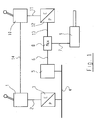
- Fig. 1 shows a schematic representation of an electropneumatic Brake system according to the invention, here only a section of the entire Brake system is shown in the area of the locomotive.
- Fig. 1 shows a driver's brake valve 1, which has an electrical line 2 with a "Analog converter" 3 of the train brake control is connected.
- the analog converter 3 converts an electrical output signal E of the driver brake valve 1 into a pressure P. around.
- the pressure output of the analog converter 3 is connected to a main air line 4, which runs from the locomotive through the entire train. From the main air line 4 branches off a pneumatic control valve 5 in the locomotive. Appropriate Control valves are also provided in the trailer vehicles (not shown).
- the pneumatic control valve 5 is via pneumatic pressure lines 6, 7 and one Maximum pressure selection valve 8 connected to a brake cylinder 9.
- an additional brake valve 10 is provided, which is connected via an electrical line 11 to an analog converter 12 of the locomotive brake control.
- the analog converter 12 converts an electrical output signal E of the additional brake valve 10 into a brake pressure signal P.
- the pneumatic output of the analog converter 12 is connected to the maximum pressure selection valve 8 via a pneumatic line 13.
- the maximum pressure selection valve 8 forwards the higher of the two pressures applied to the brake cylinder 9.
- the electropneumatic brake system is only shown very schematically here.
- the "train brake control” is formed here schematically by the driver's brake valve 1 and the analog converter 3.
- the "locomotive brake control” is formed here by the additional brake valve and the analog converter 12.
- the train brake control and the locomotive brake control are electrically connected to one another, which is indicated here by an electrical line 14 connecting the driver's brake valve 1 and the additional brake valve 10.
- the auxiliary brake valve 10 can be connected directly to the analog converter 3 via the electrical line 14.
- the mode of operation is explained in more detail below.
- the invention relates primarily a fault in which the locomotive brake control has failed and the train brake control still works electropneumatically.
- the lever of the auxiliary brake valve 10 is actuated by a not shown here Monitoring device checks whether the locomotive brake control is working properly works and a braking force is built up. Is due to a malfunction of the Locomotive brake control on the traction vehicle does not build up any braking force, so this becomes the Train brake control via the electrical line 14 "communicated". In this case the train brake control takes over braking.
- the actuation of the additional brake lever as Operation of a time-dependent driver brake lever interpreted.
- the braking request the driver is then not electrically connected to the analog converter 12 Transfer the locomotive brake control, but to the analog converter 3 of the train brake control.
- the train brake control provides an "electronic Fallback level "for the locomotive brake control.
- the analog converter 3 of the train brake control sets this "emergency signal" into one Main air line pressure around.
- the main air line pressure is then determined by the pneumatic Control valve 5 interpreted as a braking request and in a corresponding Brake pressure implemented in the brake cylinder 9.
- the additional brake valve would operate the entire train was braked only by the brakes of the locomotive. If the locomotive brake control fails, the train brake control takes over, i.e. the Train is then, if trailers are attached, also on the trailer brakes braked.
- Freight train operation can be done by the train brake control the gradient for the brake cylinder pressure build-up cannot be reached, like a functioning locomotive brake control.
- the time between the Detection of a fault and the "compensation”, i.e. the intervention of the train brake control in the present automatic monitoring against one manual monitoring reduced.
Landscapes
- Engineering & Computer Science (AREA)
- Mechanical Engineering (AREA)
- Transportation (AREA)
- Braking Systems And Boosters (AREA)
- Regulating Braking Force (AREA)
- Electric Propulsion And Braking For Vehicles (AREA)
- Valves And Accessory Devices For Braking Systems (AREA)
Abstract
Description
Das elektropneumatische Bremssystem ist hier nur sehr schematisch dargestellt. Die "Zugbremssteuerung" ist hier schematisch durch das Führerbremsventil 1 sowie den Analogwandler 3 gebildet. Die "Lokbremssteuerung" ist hier durch das Zusatzbremsventil und den Analogwandler 12 gebildet. Die Zugbremssteuerung und die Lokbremssteuerung sind elektrisch miteinander verbunden, was hier durch eine das Führerbremsventil 1 und das Zusatzbremsventil 10 verbindende elektrische Leitung 14 angedeutet ist. In der Praxis kann das Zusatzbremsventil 10 über die elektrische Leitung 14 unmittelbar mit dem Analogwandler 3 verbunden sein.
Claims (6)
- Elektropneumatisches Bremssystem für Schienenfahrzeuge, miteinem ersten vom Fahrer zu betätigenden Bedienorgan (1), das einer Zugbremssteuereinrichtung zur Ansteuerung von Zugbremsen im Normalbetrieb zugeordnet ist, undeinem zweiten vom Fahrer zu betätigenden Bedienorgan (10), das einer Lokbremssteuereinrichtung zur separaten Ansteuerung von Triebfahrzeugbremsen zugeordnet ist, insbesondere für Bremsungen im Rangierbetrieb, wobeibei einem Ausfall der Lokbremssteuereinrichtung die Zugbremssteuereinrichtung durch Betätigen des zweiten Bedienorgans (10) ansteuerbar ist.
- Elektropneumatisches Bremssystem nach Anspruch 1, dadurch gekennzeichnet, dass das erste Bedienorgan (1) ein Führerbremsventil ist, welches einen elektrischen Steuerkanal und einen redundanten pneumatischen Steuerkanal mit einem elektrischen Steuerausgang (2) bzw. einem pneumatischen Steuerausgang (3) aufweist.
- Elektropneumatisches Bremssystem nach Anspruch 2, dadurch gekennzeichnet, dass der elektrische Steuerausgang (2) mit einem elektropneumatischen Wandler (3) verbunden ist, zur Umwandlung des elektrischen Ausgangssignals des Führerbremsventils (1) in einen Hauptleitungsdruck, wobei der elektrische Kanal für Betriebsbremsungen mit ordnungsgemäß funktionierender Bremsanlage vorgesehen ist.
- Elektropneumatisches Bremssystem nach Anspruch 2 oder 3, dadurch gekennzeichnet, dass das zweite Bedienorgan (10) ein Zusatzbremsventil ist, welches über einen Datenbus (14) mit einem elektrischen Steuereingang der Zugbremssteuereinrichtung verbunden ist.
- Elektropneumatisches Bremssystem nach Anspruch 4, dadurch gekennzeichnet, dass das Zusatzbremsventil (10) über den Datenbus (14) mit dem elektropneumatischen Wandler (3) der Zugbremssteuerung verbunden ist.
- Elektropneumatisches Bremssystem nach einem der Ansprüche 2 bis 5,
dadurch gekennzeichnet, dass bei einem Ausfall des elektrischen Kanals der Hauptleitungsdruck über den pneumatischen Kanal steuerbar ist.
Applications Claiming Priority (2)
| Application Number | Priority Date | Filing Date | Title |
|---|---|---|---|
| DE10144301A DE10144301B4 (de) | 2001-09-10 | 2001-09-10 | Elektropneumatisches Bremssystem für Schienenfahrzeuge |
| DE10144301 | 2001-09-10 |
Publications (3)
| Publication Number | Publication Date |
|---|---|
| EP1291259A2 true EP1291259A2 (de) | 2003-03-12 |
| EP1291259A3 EP1291259A3 (de) | 2006-01-04 |
| EP1291259B1 EP1291259B1 (de) | 2008-04-23 |
Family
ID=7698339
Family Applications (1)
| Application Number | Title | Priority Date | Filing Date |
|---|---|---|---|
| EP02019716A Expired - Lifetime EP1291259B1 (de) | 2001-09-10 | 2002-09-03 | Elektropneumatisches Bremssystem für Schienenfahrzeuge |
Country Status (5)
| Country | Link |
|---|---|
| EP (1) | EP1291259B1 (de) |
| KR (1) | KR20030022706A (de) |
| AT (1) | ATE393070T1 (de) |
| DE (2) | DE10144301B4 (de) |
| ES (1) | ES2303843T3 (de) |
Cited By (2)
| Publication number | Priority date | Publication date | Assignee | Title |
|---|---|---|---|---|
| WO2010145943A1 (de) * | 2009-06-16 | 2010-12-23 | Siemens Aktiengesellschaft | Bedieneinrichtung und verfahren zu deren betrieb |
| WO2013131654A1 (de) * | 2012-03-09 | 2013-09-12 | Knorr-Bremse Systeme für Schienenfahrzeuge GmbH | Beobachter für einen bremsaktuatordruck sowie beobachtungsverfahren für einen bremsaktuatordruck |
Families Citing this family (3)
| Publication number | Priority date | Publication date | Assignee | Title |
|---|---|---|---|---|
| DE102006042418A1 (de) * | 2006-07-28 | 2008-02-28 | Bombardier Transportation Gmbh | Zugbremssteuerungssystem mit verbesserter Schnellbremssteuerung |
| KR200453526Y1 (ko) * | 2008-12-22 | 2011-05-11 | 이명진 | 롤스크린용 요동방지기구 |
| DE102017220893A1 (de) * | 2017-11-22 | 2019-05-23 | Knorr-Bremse Systeme für Schienenfahrzeuge GmbH | Bremssystem und Verfahren zum Ansteuern einer Bremse in dem Bremssystem |
Family Cites Families (4)
| Publication number | Priority date | Publication date | Assignee | Title |
|---|---|---|---|---|
| DE3804734A1 (de) * | 1988-02-15 | 1989-08-24 | Knorr Bremse Ag | Direkte lokbremse |
| DE19513004C2 (de) * | 1995-04-06 | 1997-09-18 | Knorr Bremse Systeme | Steuer- und Überwachungseinrichtung für Bremssysteme von Schienenfahrzeugen |
| DE19717556A1 (de) * | 1997-04-25 | 1998-10-29 | Abb Daimler Benz Transp | Bremssystem für eine Lokomotive |
| DE19755175A1 (de) * | 1997-12-11 | 1999-06-24 | Siemens Ag | Verfahren zur Bremsbetätigung beim Haltebremsbetrieb bei Lokomotiven mit automatischer Fahrzeugsteuerung |
-
2001
- 2001-09-10 DE DE10144301A patent/DE10144301B4/de not_active Expired - Fee Related
-
2002
- 2002-09-03 ES ES02019716T patent/ES2303843T3/es not_active Expired - Lifetime
- 2002-09-03 EP EP02019716A patent/EP1291259B1/de not_active Expired - Lifetime
- 2002-09-03 AT AT02019716T patent/ATE393070T1/de active
- 2002-09-03 DE DE50212135T patent/DE50212135D1/de not_active Expired - Lifetime
- 2002-09-09 KR KR1020020054093A patent/KR20030022706A/ko not_active Abandoned
Non-Patent Citations (1)
| Title |
|---|
| None |
Cited By (6)
| Publication number | Priority date | Publication date | Assignee | Title |
|---|---|---|---|---|
| WO2010145943A1 (de) * | 2009-06-16 | 2010-12-23 | Siemens Aktiengesellschaft | Bedieneinrichtung und verfahren zu deren betrieb |
| WO2013131654A1 (de) * | 2012-03-09 | 2013-09-12 | Knorr-Bremse Systeme für Schienenfahrzeuge GmbH | Beobachter für einen bremsaktuatordruck sowie beobachtungsverfahren für einen bremsaktuatordruck |
| CN104245450A (zh) * | 2012-03-09 | 2014-12-24 | 克诺尔-布里姆斯轨道车辆系统有限公司 | 用于制动执行器压力的监测器以及用于制动执行器压力的监测方法 |
| US9352736B2 (en) | 2012-03-09 | 2016-05-31 | Knorr-Bremse Systeme Fur Schienenfahrzeuge Gmbh | Monitor for brake actuator pressure and method for monitoring brake actuator pressure |
| CN104245450B (zh) * | 2012-03-09 | 2016-08-31 | 克诺尔-布里姆斯轨道车辆系统有限公司 | 用于制动执行器压力的监测器以及用于制动执行器压力的监测方法 |
| RU2624146C2 (ru) * | 2012-03-09 | 2017-06-30 | Кнорр-Бремзе Зюстеме Фюр Шиненфарцойге Гмбх | Регистратор для давления тормозного исполнительного устройства, а также способ регистрирования давления тормозного исполнительного устройства |
Also Published As
| Publication number | Publication date |
|---|---|
| DE10144301B4 (de) | 2004-04-15 |
| ES2303843T3 (es) | 2008-09-01 |
| DE50212135D1 (de) | 2008-06-05 |
| KR20030022706A (ko) | 2003-03-17 |
| ATE393070T1 (de) | 2008-05-15 |
| EP1291259A3 (de) | 2006-01-04 |
| DE10144301A1 (de) | 2003-04-30 |
| EP1291259B1 (de) | 2008-04-23 |
Similar Documents
| Publication | Publication Date | Title |
|---|---|---|
| DE102008009043B3 (de) | Elektronisch geregeltes Bremssystem mit redundanter Steuerung der Bremsaktuatoren | |
| EP3600995B1 (de) | Elektronisch steuerbares bremssystem sowie verfahren zum steuern des elektronisch steuerbaren bremssystems | |
| EP3507149B1 (de) | Verfahren zum elektronischen steuern einer bremsanlage in einem automatisiert steuerbaren nutzfahrzeug-gespann sowie elektronisch steuerbare bremsanlage in einem automatisiert steuerbaren nutzfahrzeug-gespann | |
| DE102008029310C5 (de) | Überwachungseinrichtung zur Überwachung von Systemen eines Fahrzeugs | |
| EP1123234B1 (de) | Bremssystem für ein schienenfahrzeug | |
| DE60012444T2 (de) | Integrierte elektrische und pneumatische Zugbremsen | |
| EP2576297B2 (de) | Verfahren zur steuerung einer bremsanlage eines fahrzeugs mit elektronisch geregeltem hinterachsbremskreis und pneumatisch gesteuertem vorderachsbremskreis | |
| DE2840262C2 (de) | ||
| EP2942249B1 (de) | Druckmittelbetriebenes bremssystem für ein kraftfahrzeug sowie kraftfahrzeug damit | |
| DE102005062907B3 (de) | Druckmittelbetätigtes Bremssystem mit redundanter Steuerung der Bremsaktuatoren | |
| EP3870485B1 (de) | Elektropneumatische bremssystemarchitektur ohne direkte pneumatische betriebsbremsredundanz an der hinterachse | |
| EP3317149B1 (de) | Elektrische bremseinrichtung mit vom betriebsbremsbetätigungsorgan betätigbarer feststellbremse | |
| DE69812738T2 (de) | Bremsleitung-Sensoreinheit | |
| DE19848990A1 (de) | Bremssystem für ein Schienenfahrzeug | |
| EP1847432A2 (de) | Direkte Bremsvorrichtung eines Schienenfahrzeugs mit elektronischer Regelung und zusätzlichem elektro-pneumatischen Kreis | |
| DE19848992A1 (de) | Bremssystem für ein Schienenfahrzeug | |
| DE19717556A1 (de) | Bremssystem für eine Lokomotive | |
| DE19513004C2 (de) | Steuer- und Überwachungseinrichtung für Bremssysteme von Schienenfahrzeugen | |
| DE10144301B4 (de) | Elektropneumatisches Bremssystem für Schienenfahrzeuge | |
| DE69829000T2 (de) | Integrierte elektropneumatische zugbremsen | |
| DE102019118896A1 (de) | Parkbremseinrichtung | |
| EP4486609A1 (de) | Bremssystem für ein schienenfahrzeug und verfahren zur ansteuerung eines solchen bremssystems | |
| DE10209913C1 (de) | Notbremsüberbrückungseinrichtung zur Ansteuerung von elektropneumatischen Zugbremseinrichtungen in Triebfahrzeugen und Steuerwagen mit konventioneller Bremstechnik | |
| DE102022117696C5 (de) | Anordnung und Verfahren zum Hilfslösen einer Bremse eines Schienenfahrzeugs sowie Schienenfahrzeug | |
| DE102019105224B4 (de) | Bremse für Schienenfahrzeuge und Verfahren zum Steuern einer Bremse für Schienenfahrzeuge |
Legal Events
| Date | Code | Title | Description |
|---|---|---|---|
| PUAI | Public reference made under article 153(3) epc to a published international application that has entered the european phase |
Free format text: ORIGINAL CODE: 0009012 |
|
| AK | Designated contracting states |
Kind code of ref document: A2 Designated state(s): AT BE BG CH CY CZ DE DK EE ES FI FR GB GR IE IT LI LU MC NL PT SE SK TR |
|
| AX | Request for extension of the european patent |
Extension state: AL LT LV MK RO SI |
|
| PUAL | Search report despatched |
Free format text: ORIGINAL CODE: 0009013 |
|
| AK | Designated contracting states |
Kind code of ref document: A3 Designated state(s): AT BE BG CH CY CZ DE DK EE ES FI FR GB GR IE IT LI LU MC NL PT SE SK TR |
|
| AX | Request for extension of the european patent |
Extension state: AL LT LV MK RO SI |
|
| 17P | Request for examination filed |
Effective date: 20060704 |
|
| AKX | Designation fees paid |
Designated state(s): AT BE BG CH CY CZ DE DK EE ES FI FR GB GR IE IT LI LU MC NL PT SE SK TR |
|
| GRAP | Despatch of communication of intention to grant a patent |
Free format text: ORIGINAL CODE: EPIDOSNIGR1 |
|
| GRAS | Grant fee paid |
Free format text: ORIGINAL CODE: EPIDOSNIGR3 |
|
| GRAA | (expected) grant |
Free format text: ORIGINAL CODE: 0009210 |
|
| AK | Designated contracting states |
Kind code of ref document: B1 Designated state(s): AT BE BG CH CY CZ DE DK EE ES FI FR GB GR IE IT LI LU MC NL PT SE SK TR |
|
| REG | Reference to a national code |
Ref country code: GB Ref legal event code: FG4D Free format text: NOT ENGLISH |
|
| REG | Reference to a national code |
Ref country code: CH Ref legal event code: EP |
|
| REF | Corresponds to: |
Ref document number: 50212135 Country of ref document: DE Date of ref document: 20080605 Kind code of ref document: P |
|
| REG | Reference to a national code |
Ref country code: IE Ref legal event code: FG4D Free format text: LANGUAGE OF EP DOCUMENT: GERMAN |
|
| REG | Reference to a national code |
Ref country code: CH Ref legal event code: NV Representative=s name: ISLER & PEDRAZZINI AG |
|
| REG | Reference to a national code |
Ref country code: ES Ref legal event code: FG2A Ref document number: 2303843 Country of ref document: ES Kind code of ref document: T3 |
|
| NLV1 | Nl: lapsed or annulled due to failure to fulfill the requirements of art. 29p and 29m of the patents act | ||
| PG25 | Lapsed in a contracting state [announced via postgrant information from national office to epo] |
Ref country code: FI Free format text: LAPSE BECAUSE OF FAILURE TO SUBMIT A TRANSLATION OF THE DESCRIPTION OR TO PAY THE FEE WITHIN THE PRESCRIBED TIME-LIMIT Effective date: 20080423 Ref country code: PT Free format text: LAPSE BECAUSE OF FAILURE TO SUBMIT A TRANSLATION OF THE DESCRIPTION OR TO PAY THE FEE WITHIN THE PRESCRIBED TIME-LIMIT Effective date: 20080923 Ref country code: BG Free format text: LAPSE BECAUSE OF FAILURE TO SUBMIT A TRANSLATION OF THE DESCRIPTION OR TO PAY THE FEE WITHIN THE PRESCRIBED TIME-LIMIT Effective date: 20080723 Ref country code: NL Free format text: LAPSE BECAUSE OF FAILURE TO SUBMIT A TRANSLATION OF THE DESCRIPTION OR TO PAY THE FEE WITHIN THE PRESCRIBED TIME-LIMIT Effective date: 20080423 |
|
| REG | Reference to a national code |
Ref country code: IE Ref legal event code: FD4D |
|
| ET | Fr: translation filed | ||
| PG25 | Lapsed in a contracting state [announced via postgrant information from national office to epo] |
Ref country code: SE Free format text: LAPSE BECAUSE OF FAILURE TO SUBMIT A TRANSLATION OF THE DESCRIPTION OR TO PAY THE FEE WITHIN THE PRESCRIBED TIME-LIMIT Effective date: 20080723 Ref country code: IE Free format text: LAPSE BECAUSE OF FAILURE TO SUBMIT A TRANSLATION OF THE DESCRIPTION OR TO PAY THE FEE WITHIN THE PRESCRIBED TIME-LIMIT Effective date: 20080423 Ref country code: DK Free format text: LAPSE BECAUSE OF FAILURE TO SUBMIT A TRANSLATION OF THE DESCRIPTION OR TO PAY THE FEE WITHIN THE PRESCRIBED TIME-LIMIT Effective date: 20080423 |
|
| PG25 | Lapsed in a contracting state [announced via postgrant information from national office to epo] |
Ref country code: SK Free format text: LAPSE BECAUSE OF FAILURE TO SUBMIT A TRANSLATION OF THE DESCRIPTION OR TO PAY THE FEE WITHIN THE PRESCRIBED TIME-LIMIT Effective date: 20080423 |
|
| PLBE | No opposition filed within time limit |
Free format text: ORIGINAL CODE: 0009261 |
|
| STAA | Information on the status of an ep patent application or granted ep patent |
Free format text: STATUS: NO OPPOSITION FILED WITHIN TIME LIMIT |
|
| BERE | Be: lapsed |
Owner name: KNORR-BREMSE SYSTEME FUR SCHIENENFAHRZEUGE G.M.B. Effective date: 20080930 |
|
| 26N | No opposition filed |
Effective date: 20090126 |
|
| PG25 | Lapsed in a contracting state [announced via postgrant information from national office to epo] |
Ref country code: EE Free format text: LAPSE BECAUSE OF FAILURE TO SUBMIT A TRANSLATION OF THE DESCRIPTION OR TO PAY THE FEE WITHIN THE PRESCRIBED TIME-LIMIT Effective date: 20080423 Ref country code: MC Free format text: LAPSE BECAUSE OF NON-PAYMENT OF DUE FEES Effective date: 20080930 |
|
| GBPC | Gb: european patent ceased through non-payment of renewal fee |
Effective date: 20080903 |
|
| PG25 | Lapsed in a contracting state [announced via postgrant information from national office to epo] |
Ref country code: BE Free format text: LAPSE BECAUSE OF NON-PAYMENT OF DUE FEES Effective date: 20080930 |
|
| PG25 | Lapsed in a contracting state [announced via postgrant information from national office to epo] |
Ref country code: GB Free format text: LAPSE BECAUSE OF NON-PAYMENT OF DUE FEES Effective date: 20080903 |
|
| PG25 | Lapsed in a contracting state [announced via postgrant information from national office to epo] |
Ref country code: CY Free format text: LAPSE BECAUSE OF FAILURE TO SUBMIT A TRANSLATION OF THE DESCRIPTION OR TO PAY THE FEE WITHIN THE PRESCRIBED TIME-LIMIT Effective date: 20080423 Ref country code: LU Free format text: LAPSE BECAUSE OF NON-PAYMENT OF DUE FEES Effective date: 20080903 |
|
| PG25 | Lapsed in a contracting state [announced via postgrant information from national office to epo] |
Ref country code: TR Free format text: LAPSE BECAUSE OF FAILURE TO SUBMIT A TRANSLATION OF THE DESCRIPTION OR TO PAY THE FEE WITHIN THE PRESCRIBED TIME-LIMIT Effective date: 20080423 |
|
| PG25 | Lapsed in a contracting state [announced via postgrant information from national office to epo] |
Ref country code: GR Free format text: LAPSE BECAUSE OF FAILURE TO SUBMIT A TRANSLATION OF THE DESCRIPTION OR TO PAY THE FEE WITHIN THE PRESCRIBED TIME-LIMIT Effective date: 20080724 |
|
| PGFP | Annual fee paid to national office [announced via postgrant information from national office to epo] |
Ref country code: CH Payment date: 20110926 Year of fee payment: 10 |
|
| PGFP | Annual fee paid to national office [announced via postgrant information from national office to epo] |
Ref country code: AT Payment date: 20110922 Year of fee payment: 10 |
|
| REG | Reference to a national code |
Ref country code: CH Ref legal event code: PL |
|
| REG | Reference to a national code |
Ref country code: AT Ref legal event code: MM01 Ref document number: 393070 Country of ref document: AT Kind code of ref document: T Effective date: 20120903 |
|
| PG25 | Lapsed in a contracting state [announced via postgrant information from national office to epo] |
Ref country code: AT Free format text: LAPSE BECAUSE OF NON-PAYMENT OF DUE FEES Effective date: 20120903 Ref country code: CH Free format text: LAPSE BECAUSE OF NON-PAYMENT OF DUE FEES Effective date: 20120930 Ref country code: LI Free format text: LAPSE BECAUSE OF NON-PAYMENT OF DUE FEES Effective date: 20120930 |
|
| REG | Reference to a national code |
Ref country code: FR Ref legal event code: PLFP Year of fee payment: 15 |
|
| PGFP | Annual fee paid to national office [announced via postgrant information from national office to epo] |
Ref country code: FR Payment date: 20160922 Year of fee payment: 15 Ref country code: CZ Payment date: 20160825 Year of fee payment: 15 |
|
| PGFP | Annual fee paid to national office [announced via postgrant information from national office to epo] |
Ref country code: ES Payment date: 20160923 Year of fee payment: 15 |
|
| PG25 | Lapsed in a contracting state [announced via postgrant information from national office to epo] |
Ref country code: CZ Free format text: LAPSE BECAUSE OF NON-PAYMENT OF DUE FEES Effective date: 20170903 |
|
| REG | Reference to a national code |
Ref country code: FR Ref legal event code: ST Effective date: 20180531 |
|
| PG25 | Lapsed in a contracting state [announced via postgrant information from national office to epo] |
Ref country code: FR Free format text: LAPSE BECAUSE OF NON-PAYMENT OF DUE FEES Effective date: 20171002 |
|
| REG | Reference to a national code |
Ref country code: ES Ref legal event code: FD2A Effective date: 20181024 |
|
| PGFP | Annual fee paid to national office [announced via postgrant information from national office to epo] |
Ref country code: IT Payment date: 20180921 Year of fee payment: 17 |
|
| PG25 | Lapsed in a contracting state [announced via postgrant information from national office to epo] |
Ref country code: ES Free format text: LAPSE BECAUSE OF NON-PAYMENT OF DUE FEES Effective date: 20170904 |
|
| PGFP | Annual fee paid to national office [announced via postgrant information from national office to epo] |
Ref country code: DE Payment date: 20190923 Year of fee payment: 18 |
|
| PG25 | Lapsed in a contracting state [announced via postgrant information from national office to epo] |
Ref country code: IT Free format text: LAPSE BECAUSE OF NON-PAYMENT OF DUE FEES Effective date: 20190903 |
|
| REG | Reference to a national code |
Ref country code: DE Ref legal event code: R119 Ref document number: 50212135 Country of ref document: DE |
|
| PG25 | Lapsed in a contracting state [announced via postgrant information from national office to epo] |
Ref country code: DE Free format text: LAPSE BECAUSE OF NON-PAYMENT OF DUE FEES Effective date: 20210401 |