EP1291202A2 - Temperature determination through a transmitter and on the controller board integrated temperature sensor - Google Patents
Temperature determination through a transmitter and on the controller board integrated temperature sensor Download PDFInfo
- Publication number
- EP1291202A2 EP1291202A2 EP02017969A EP02017969A EP1291202A2 EP 1291202 A2 EP1291202 A2 EP 1291202A2 EP 02017969 A EP02017969 A EP 02017969A EP 02017969 A EP02017969 A EP 02017969A EP 1291202 A2 EP1291202 A2 EP 1291202A2
- Authority
- EP
- European Patent Office
- Prior art keywords
- temperature sensor
- transmitter
- heater according
- heater
- control unit
- Prior art date
- Legal status (The legal status is an assumption and is not a legal conclusion. Google has not performed a legal analysis and makes no representation as to the accuracy of the status listed.)
- Withdrawn
Links
Images
Classifications
-
- B—PERFORMING OPERATIONS; TRANSPORTING
- B60—VEHICLES IN GENERAL
- B60H—ARRANGEMENTS OF HEATING, COOLING, VENTILATING OR OTHER AIR-TREATING DEVICES SPECIALLY ADAPTED FOR PASSENGER OR GOODS SPACES OF VEHICLES
- B60H1/00—Heating, cooling or ventilating devices
- B60H1/22—Heating, cooling or ventilating devices the heat source being other than the propulsion plant
- B60H1/2203—Heating, cooling or ventilating devices the heat source being other than the propulsion plant the heat being derived from burners
-
- B—PERFORMING OPERATIONS; TRANSPORTING
- B60—VEHICLES IN GENERAL
- B60H—ARRANGEMENTS OF HEATING, COOLING, VENTILATING OR OTHER AIR-TREATING DEVICES SPECIALLY ADAPTED FOR PASSENGER OR GOODS SPACES OF VEHICLES
- B60H1/00—Heating, cooling or ventilating devices
- B60H1/22—Heating, cooling or ventilating devices the heat source being other than the propulsion plant
- B60H2001/2268—Constructional features
- B60H2001/2271—Heat exchangers, burners, ignition devices
-
- B—PERFORMING OPERATIONS; TRANSPORTING
- B60—VEHICLES IN GENERAL
- B60H—ARRANGEMENTS OF HEATING, COOLING, VENTILATING OR OTHER AIR-TREATING DEVICES SPECIALLY ADAPTED FOR PASSENGER OR GOODS SPACES OF VEHICLES
- B60H1/00—Heating, cooling or ventilating devices
- B60H1/22—Heating, cooling or ventilating devices the heat source being other than the propulsion plant
- B60H2001/2268—Constructional features
- B60H2001/2278—Connectors, water supply, housing, mounting brackets
-
- F—MECHANICAL ENGINEERING; LIGHTING; HEATING; WEAPONS; BLASTING
- F24—HEATING; RANGES; VENTILATING
- F24H—FLUID HEATERS, e.g. WATER OR AIR HEATERS, HAVING HEAT-GENERATING MEANS, e.g. HEAT PUMPS, IN GENERAL
- F24H1/00—Water heaters, e.g. boilers, continuous-flow heaters or water-storage heaters
- F24H1/22—Water heaters other than continuous-flow or water-storage heaters, e.g. water heaters for central heating
- F24H1/24—Water heaters other than continuous-flow or water-storage heaters, e.g. water heaters for central heating with water mantle surrounding the combustion chamber or chambers
- F24H1/26—Water heaters other than continuous-flow or water-storage heaters, e.g. water heaters for central heating with water mantle surrounding the combustion chamber or chambers the water mantle forming an integral body
Definitions
- the invention relates to a heater, in particular with liquid fuel operated water or air heater one Motor vehicle in the form of an auxiliary heater or an auxiliary heater, with a housing jacket and a heat exchanger as well with an electronic control unit for regulation or Monitoring of the heating operation with the help of at least one temperature sensor, in particular control temperature sensor and / or Overheating sensor.
- a temperature sensor in the form of a control temperature sensor used, preferably in the air or Water duct arranged in the area of the heat exchanger and actual value generator of a control loop.
- the control unit regulates the heating power in such a way that the room temperature the specified target value with as little deviation as possible equivalent.
- Another temperature sensor in the form of a Overheating sensor located at a suitable hot spot in the heater, especially in the calotte area of a heat exchanger, is used to limit the upper temperature of the heater by turning off the heater to an overheating condition in the heater.
- Such a vehicle heater is for example from DE 44 46 829 A1 known.
- the disadvantage is that the control temperature sensor and the overheating sensor as separate components longer cables, contacts and single wire seals prefabricated are individually arranged and sent to assembly, assembled and held by separate components. Both Sensors are identical components and can be plugged into the control unit be exchanged. To regulate the heating output and the safety against overheating and a burning of the To ensure heat exchanger comes the safe contact the separate temperature sensors on the surface of the heat exchanger special meaning too. The sensor in question must follow "movements" and thermal expansion. The efficiency the known system is basically very well, the cost of manufacturing is relatively high.
- the heater is advantageously further developed by the features of dependent claims 2 to 17.
- the essence of the invention is that in the area of the control unit board of the control unit arranged on the control unit board connected temperature sensor a highly thermally conductive Temperature transmission element, a so-called transmitter, contacted, which in turn through an opening in the housing jacket, in particular water jacket, extends towards the heat exchanger.
- a highly thermally conductive Temperature transmission element a so-called transmitter, contacted, which in turn through an opening in the housing jacket, in particular water jacket, extends towards the heat exchanger.
- a separate one Temperature sensor according to the prior art is invented a much cheaper less sensitive Transmission element, namely the "transmitter”, as a probe used in the temperature range of the heater to be measured to penetrate, with a water heater Transmitter is preferably immersed in the heating water and / or contacted with the heat exchanger surface. At this Transmitter engages the one positioned on the control unit board Temperature sensor the temperatures from.
- the temperature sensor is preferably as a component on the circuit board of the Control unit or the control unit board soldered. therefore can by the invention on separate complex temperature sensors to be dispensed with. A typical one for applicant heaters "Direct" detection of the heat exchanger surface temperature is still possible.
- the invention is suitable for all air and water heaters of all performance classes, especially in motor vehicles.
- a temperature sensor can already be used in control unit production placed on the control board and the prefabricated Control unit board with connected temperature sensor on the heater easily and quickly with the transmitter positioned be assembled. This serves as a positioning aid the opening in the casing.
- the transmitter preferably has a fitting housing part a peripheral recess, wherein the outer periphery of the fitting housing part in a sliding seat in the fitting opening directly or recorded indirectly. This is the insertion the transmitter into the fitting opening and jamming or jamming minimized.
- sealing ring in the peripheral recess, the one for a good seal of the one in the heater medium to be heated, air or water.
- a particularly useful embodiment provides that only the heat-insulating sealing ring as a fitting opening Contacted trained opening of the housing shell, and not the transmitter, which is a highly thermally conductive component is. In this way, heat does not come through heat conduction in the adjacent casing, but remains in the Transmitter.
- Another embodiment provides that the temperature sensor in addition to a transmitter located in the control unit Pressure spring supported on a protective housing of the control unit are. When the transmitter and temperature sensor are installed this ensures that, for example, due to temperature fluctuations caused expansion (movements) of the Heat exchanger without damaging the transmitter, the temperature sensor, of the control unit or the heat exchanger can be.
- the housing jacket preferably has an axial extension of the Fitting opening at least one radially away from the fitting opening outward projection on which the control unit board is supported flat. This results in a solid, stable support for the control unit board.
- the control unit board can be at a distance from the housing jacket are preferably arranged axially parallel. The Distance creates a heat-insulating air gap between Housing jacket and control unit board.
- the transmitter in particular has an essentially cylindrical shape on.
- the control unit board is preferably detachable on the or attached to the projections and flat on these projections supported.
- the top of the control unit board is in a distance from the protective housing to an installation space to create electronic components that are preferred attached and connected to the top of the control unit board are.
- the temperature sensor is preferably an integrated component the control unit board, which is on the control unit board plugged in, soldered or otherwise is attached.
- a possible connection cable can thereby have a short length. Single wire seals are not required.
- the transmitter can on a radially inner stop of the Heater spring-biased by the force of the compression spring his.
- the radially inner stop can be a shoulder or a Taper in the opening of the housing jacket.
- the radially inner stop is particularly preferred Shell surface of the heat exchanger itself, which in particular is a contact surface of the temperature sensor, its temperature is to be monitored. This is a safer, game-free and voltage-free contact of the transmitter and the temperature sensor to the heat exchanger made with simple means, without the risk of damaging the sensor and the transmitter in operation due to possible temperature fluctuations or thermal expansion.
- the temperature sensor can be a single sensor, in particular a superheating temperature sensor or a control temperature sensor, with several on a single control unit board spaced apart temperature sensors could be. Each temperature sensor is then its own Assigned transmitter.
- the temperature sensor is preferably a combination sensor, which is the overheating sensor and the control temperature sensor as a unit that contains advantages in manufacturing and in of assembly. Overheating sensor and control temperature sensor can then not be interchanged during assembly become. Overheating sensor and control temperature sensor have their own transmitters.
- the protective housing itself is solid and watertight with the housing jacket connected, especially screwed.
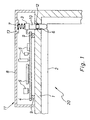
- the heater is, in particular, a liquid fuel-operated one Water heater 20 of a motor vehicle in the form a parking heater and has, among other things, a housing jacket 1 in the form of a water jacket, a heat exchanger 2 and a control unit 11 for regulating or monitoring the Heating operation with the help of a temperature sensor 3.
- the temperature sensor 3 is on the side of a control unit board 4 of the control device 11 and arranged on the control device board soldered positioned over connection cable.
- the Temperature sensor 3 extends downwards according to the drawing, being directly on the underside of the temperature sensor 3 a highly thermally conductive heat transfer element, a so-called Transmitter 10, contacts and connects through an opening 6 of the housing shell 1 in the direction of the heat exchanger 2 extends.
- the one connected to the bottom of the temperature sensor 3 Transmitter 10 is slidable in the form of a fitting opening Opening 6 of the housing shell 1 is added.
- the transmitter 10 has a fitting housing part with a peripheral recess on, with the outer periphery of the fitting housing part received in a sliding seat in the fitting opening can be.
- a sealing ring 12 is received in the circumferential recess, which is designed so that in the embodiment the drawing only the sealing ring 12 the housing shell 1 contacted in the area of the fitting opening.
- the transmitter 10 and the temperature sensor 3 are via a compression spring 7 located in control unit 11 on a protective housing 8 of the control unit 11 supported. There is a corresponding one for this Fit recess in an integrated in the protective housing 8 Projection 13 for the positive reception of the upper Axial end of the compression spring 7 is provided.
- the housing shell 1 has an axial extension of the fitting opening two radially outward from the fitting opening spaced apart projections 9 on which the Control unit board 4 is plugged on and supported flat.
- the top of the control unit board 4 is in one Distance to protective housing 8. At the top of the control unit board 4 are various not of interest here electronic components 5 attached and connected.
- the transmitter 10 is at a radially inner stop of the Heater spring-biased by the force of the compression spring 7.
- the radially inner stop is in particular an outer surface of the heat exchanger 2.
- the outer surface is a radial raised contact surface for the transmitter 10, the Temperature is to be monitored.
- the protective housing 8 is solid and waterproof with the housing jacket 1 screwed.
- the aforementioned water heater 20 is simple, Assemble quickly and safely and especially inexpensively finished.
- the temperature sensor 3 is already in the control unit manufacturing on the control unit board 4 and connected. Furthermore, the control board is pre-manufactured the electronic components 5 set and connected.
- the sealing ring 12 is in the associated via the transmitter 10
- the circumferential recess is turned over, and the transmitter 10 including sealing ring 12 in the radial fitting opening of the housing shell 1 used.
- the first one according to the drawing The end of the transmitter 10 touches the radial one Projection of the jacket of the heat exchanger 2.
- the prefabricated control unit board 4 on the projections 9 inserted, then the temperature sensor 3 the axial upper Side of the transmitter 10 contacted.
- the temperature sensor 3 and the preferably cylindrical transmitter 10 are here axially aligned with each other. Following this, in axial alignment to the two aforementioned components Compression spring 7 placed on the temperature sensor 3.
- the protective housing 8 is placed on the housing jacket 1 so that in the recess in the projection 13 the upper Engages end of the compression spring 7.
- the protective housing 8 is screwed tightly and watertight to the casing.
- To the compression spring 7 is spring-biased in a manner that on the one hand the transmitter 10 securely on the heat exchanger 2 and on the other hand, the transmitter 10 safely on Temperature sensor 3 is present, but transmitter 10 and temperature sensor 3 can give way radially outward when elevated Tensions are present.
- the axial alignment is also then the compression spring 7, the temperature sensor 3 and the transmitter 10 guaranteed.
- An axial displacement of the aforementioned Components is replaced by the connecting cable of the Temperature sensor 3 balanced, which to the control unit board 4 leads.
Landscapes
- Physics & Mathematics (AREA)
- Thermal Sciences (AREA)
- Engineering & Computer Science (AREA)
- Mechanical Engineering (AREA)
- Air-Conditioning For Vehicles (AREA)
- Measuring Temperature Or Quantity Of Heat (AREA)
Abstract
Description
Die Erfindung betrifft ein Heizgerät, insbesondere mit Flüssigbrennstoff betriebenes Wasser- oder Luftheizgerät eines Kraftfahrzeuges in Form eines Zuheizers oder einer Standheizung, mit einem Gehäusemantel und einem Wärmetauscher sowie mit einem elektronischen Steuergerät zur Regelung bzw. Überwachung des Heizbetriebes mit Hilfe zumindest eines Temperaturfühlers, insbesondere Regeltemperaturfühlers und/oder Überhitzungsfühlers.The invention relates to a heater, in particular with liquid fuel operated water or air heater one Motor vehicle in the form of an auxiliary heater or an auxiliary heater, with a housing jacket and a heat exchanger as well with an electronic control unit for regulation or Monitoring of the heating operation with the help of at least one temperature sensor, in particular control temperature sensor and / or Overheating sensor.
Bei Fahrzeugheizgeräten der vorgenannten Art wird für die Raumtemperaturregelung ein Temperaturfühler in Form eines Regeltemperaturfühlers verwendet, der vorzugsweise im Luftoder Wasserführungskanal im Bereich des Wärmetauschers angeordnet und Istwertgeber eines Regelkreises ist. Das Steuergerät regelt die Heizleistung in der Weise, daß die Raumtemperatur dem vorgegebenen Sollwert mit möglichst geringer Abweichung entspricht. Ein weiterer Temperaturfühler in Form eines Überhitzungsfühlers, der an geeigneter heißer Stelle im Heizgerät, insbesondere im Kalottenbereich eines Wärmetauschers, liegt, dient zur oberen Temperaturbegrenzung des Heizgerätes durch Abschalten des Heizgerätes, um einen Überhitzungszustand im Heizgerät auszuschließen.In vehicle heaters of the aforementioned type is used for the Room temperature control a temperature sensor in the form of a control temperature sensor used, preferably in the air or Water duct arranged in the area of the heat exchanger and actual value generator of a control loop. The control unit regulates the heating power in such a way that the room temperature the specified target value with as little deviation as possible equivalent. Another temperature sensor in the form of a Overheating sensor located at a suitable hot spot in the heater, especially in the calotte area of a heat exchanger, is used to limit the upper temperature of the heater by turning off the heater to an overheating condition in the heater.
Ein derartiges Fahrzeugheizgerät ist beispielsweise aus DE 44 46 829 A1 bekannt. Von Nachteil ist, daß der Regeltemperaturfühler und der Überhitzungsfühler als separate Bauteile mit längeren Kabeln, Kontakten und Einzeladerabdichtungen vorgefertigt sind und einzeln disponiert, der Montage zugeführt, montiert und von separaten Bauteilen gehalten werden. Beide Fühler sind identische Bauteile und können am Steuergerätestecker vertauscht werden. Um die Regelung der Heizleistung und die Sicherheit vor Überhitzung und ein Durchbrennen des Wärmetauschers zu gewährleisten, kommt der sicheren Kontaktierung der separaten Temperatursensoren an der Wärmetauscher-Oberfläche besondere Bedeutung zu. Der betreffende Sensor muß "Bewegungen" und Wärmeausdehnungen folgen. Die Leistungsfähigkeit des bekannten Systems ist grundsätzlich sehr gut, die Kosten der Fertigung sind jedoch relativ hoch.Such a vehicle heater is for example from DE 44 46 829 A1 known. The disadvantage is that the control temperature sensor and the overheating sensor as separate components longer cables, contacts and single wire seals prefabricated are individually arranged and sent to assembly, assembled and held by separate components. Both Sensors are identical components and can be plugged into the control unit be exchanged. To regulate the heating output and the safety against overheating and a burning of the To ensure heat exchanger comes the safe contact the separate temperature sensors on the surface of the heat exchanger special meaning too. The sensor in question must follow "movements" and thermal expansion. The efficiency the known system is basically very well, the cost of manufacturing is relatively high.
Ausgehend vom vorgenannten Stand der Technik ist es Aufgabe der Erfindung, ein Heizgerät der eingahgs genannten Art derart weiterzubilden, daß es einfach, schnell und sicher montiert werden kann, zuverlässig im Betrieb ist und insbesondere mit geringem Fertigungsaufwand einhergeht.Starting from the aforementioned prior art, it is a task the invention, a heater of the type mentioned to further train that it can be installed easily, quickly and safely can be, is reliable in operation and in particular goes hand in hand with low manufacturing costs.
Gelöst wird die der Erfindung zugrundeliegende Aufgabe durch ein Heizgerät der im unabhängigen Anspruch 1 angegebenen Art.The object on which the invention is based is achieved by a heater of the type specified in independent claim 1.
Vorteilhaft weitergebildet wird das Heizgerät durch die Merkmale der abhängigen Ansprüche 2 bis 17.The heater is advantageously further developed by the features of dependent claims 2 to 17.
Wesen der Erfindung ist, daß der im Bereich der Steuergeräteplatine des Steuergeräts angeordnete, an der Steuergeräteplatine angeschlossene Temperaturfühler ein hoch-wärmeleitendes Temperatur-Übertragungselement, einen sogenannten Transmitter, kontaktiert, welches bzw. welcher sich seinerseits durch eine Öffnung des Gehäusemantels, insbesondere Wassermantels, in Richtung Wärmetauscher erstreckt. Anstelle eines separaten Temperaturfühlers nach dem Stand der Technik wird erfindungsgemäß ein wesentlich kostengünstigeres unempfindlicheres Übertragungselement, nämlich der "Transmitter", als Sonde dazu verwendet, in den zu messenden Temperaturbereich des Heizgerätes vorzudringen, wobei bei einem Wasserheizgerät der Transmitter vorzugsweise ins Heizwasser getaucht ist und/oder mit der Wärmetauscher-Oberfläche kontaktiert. An diesem Transmitter greift der auf der Steuergeräteplatine positionierte Temperaturfühler die Temperaturen ab. Der Temperaturfühler ist vorzugsweise als Bauteil auf der Leiterplatte des Steuergeräts bzw. der Steuergeräteplatine gelötet. Mithin kann durch die Erfindung auf separate aufwendige Temperaturfühler verzichtet werden. Eine für Anmelder-Heizgeräte typische "direkte" Erfassung der Wärmetauscheroberflächen-Temperatur ist weiterhin möglich. Die Erfindung eignet sich für alle Luft- und Wasserheizgeräte jeglicher Leistungsklasse, insbesondere bei Kraftfahrzeugen.The essence of the invention is that in the area of the control unit board of the control unit arranged on the control unit board connected temperature sensor a highly thermally conductive Temperature transmission element, a so-called transmitter, contacted, which in turn through an opening in the housing jacket, in particular water jacket, extends towards the heat exchanger. Instead of a separate one Temperature sensor according to the prior art is invented a much cheaper less sensitive Transmission element, namely the "transmitter", as a probe used in the temperature range of the heater to be measured to penetrate, with a water heater Transmitter is preferably immersed in the heating water and / or contacted with the heat exchanger surface. At this Transmitter engages the one positioned on the control unit board Temperature sensor the temperatures from. The temperature sensor is preferably as a component on the circuit board of the Control unit or the control unit board soldered. therefore can by the invention on separate complex temperature sensors to be dispensed with. A typical one for applicant heaters "Direct" detection of the heat exchanger surface temperature is still possible. The invention is suitable for all air and water heaters of all performance classes, especially in motor vehicles.
Ein Temperaturfühler kann bereits bei der Steuergerätefertigung auf die Steuergeräteplatine gesetzt und die vorgefertigte Steuergeräteplatine nebst angeschlossenem Temperaturfühler am Heizgerät leicht und schnell mit positioniertem Transmitter endmontiert werden. Als Positionierhilfe dient hierbei die Öffnung im Gehäusemantel.A temperature sensor can already be used in control unit production placed on the control board and the prefabricated Control unit board with connected temperature sensor on the heater easily and quickly with the transmitter positioned be assembled. This serves as a positioning aid the opening in the casing.
Vorzugsweise ist der die Unterseite des Temperaturfühlers kontaktierende Transmitter verschieblich in der als Paßöffnung ausgebildeten Öffnung des Gehäusemantels aufgenommen. Dadurch ist eine Feinpositionierung des Transmitters möglich. Außerdem kann die Erstreckungstiefe des Transmitters in Richtung Wärmetauscher gegebenenfalls exakt eingestellt werden.This is preferably the underside of the temperature sensor Contacting transmitter slidably in the as a fitting opening trained opening of the housing shell added. This enables fine positioning of the transmitter. In addition, the depth of extension of the transmitter can be in the direction Heat exchanger can be set exactly if necessary.
Der Transmitter weist vorzugsweise einen Paßgehäuseteil mit einer Umfangsaussparung auf, wobei der Außenumfang des Paßgehäuseteils in einem Verschiebesitz in der Paßöffnung direkt oder indirekt aufgenommen ist. Dadurch ist das Einschieben des Transmitters in die Paßöffnung erleichtert und ein Verklemmen oder Verkanten minimiert.The transmitter preferably has a fitting housing part a peripheral recess, wherein the outer periphery of the fitting housing part in a sliding seat in the fitting opening directly or recorded indirectly. This is the insertion the transmitter into the fitting opening and jamming or jamming minimized.
Bevorzugt befindet sich in der Umfangsaussparung ein Dichtring, der für eine gute Abdichtung des im Heizgerät geführten aufzuheizenden Mediums, Luft oder Wasser, sorgt.There is preferably a sealing ring in the peripheral recess, the one for a good seal of the one in the heater medium to be heated, air or water.
Eine besonders zweckmäßige Ausführungsvariante sieht vor, daß ausschließlich der wärmeisolierende Dichtring die als Paßöffnung ausgebildete Öffnung des Gehäusemantels kontaktiert, und nicht der Transmitter, der ein hoch-wärmeleitendes Bauteil ist. Auf diese Weise gelangt Wärme nicht durch Wärmeleitung in den benachbarten Gehäusemantel, sondern verbleibt im Transmitter. A particularly useful embodiment provides that only the heat-insulating sealing ring as a fitting opening Contacted trained opening of the housing shell, and not the transmitter, which is a highly thermally conductive component is. In this way, heat does not come through heat conduction in the adjacent casing, but remains in the Transmitter.
Eine andere Ausführungsform sieht vor, daß der Temperaturfühler nebst Transmitter über eine im Steuergerät befindliche Druckfeder an einem Schutzgehäuse des Steuergeräts abgestützt sind. Im eingebauten Zustand des Transmitters und Temperaturfühlers wird damit gewährleistet, daß zum Beispiel durch Temperaturschwankungen verursachte Ausdehnungen (Bewegungen) des Wärmetauschers ohne Schädigung des Transmitters, des Temperaturfühlers, des Steuergeräts oder des Wärmetauschers absorbiert werden können.Another embodiment provides that the temperature sensor in addition to a transmitter located in the control unit Pressure spring supported on a protective housing of the control unit are. When the transmitter and temperature sensor are installed this ensures that, for example, due to temperature fluctuations caused expansion (movements) of the Heat exchanger without damaging the transmitter, the temperature sensor, of the control unit or the heat exchanger can be.
Vorzugsweise weist der Gehäusemantel in Axialverlängerung der Paßöffnung zumindest einen von der Paßöffnung entfernten, radial nach außen gerichteten Vorsprung auf, auf dem die Steuergeräteplatine flächig abgestützt ist. Dadurch ergibt sich eine satte, stabile Auflage für die Steuergeräteplatine. Außerdem kann die Steuergeräteplatine in einem Abstand zum Gehäusemantel vorzugsweise achsparallel angeordnet werden. Der Abstand schafft einen wärmeisolierenden Luftspalt zwischen Gehäusemantel und Steuergeräteplatine.The housing jacket preferably has an axial extension of the Fitting opening at least one radially away from the fitting opening outward projection on which the control unit board is supported flat. This results in a solid, stable support for the control unit board. Moreover the control unit board can be at a distance from the housing jacket are preferably arranged axially parallel. The Distance creates a heat-insulating air gap between Housing jacket and control unit board.
Der Transmitter weist insbesondere im wesentlichen Zylinderform auf.The transmitter in particular has an essentially cylindrical shape on.
Die Steuergeräteplatine ist vorzugsweise lösbar auf dem oder den Vorsprüngen aufgesteckt und flächig an diesen Vorsprüngen abgestützt.The control unit board is preferably detachable on the or attached to the projections and flat on these projections supported.
Im besonderen ist die Oberseite der Steuergeräteplatine in einem Abstand zum Schutzgehäuse angeordnet, um einen Einbauraum für elektronische Bauteile zu schaffen, die vorzugsweise an der Oberseite der Steuergeräteplatine befestigt und angeschlossen sind.In particular, the top of the control unit board is in a distance from the protective housing to an installation space to create electronic components that are preferred attached and connected to the top of the control unit board are.
Der Temperaturfühler ist mit Vorzug ein integriertes Bauteil der Steuergeräteplatine, welches an der Steuergeräteplatine anschlußherstellend angesteckt, angelötet oder anderweitig befestigt ist. Ein mögliches Anschlußkabel kann dadurch eine kurze Länge aufweisen. Einzeladerabdichtungen entfallen.The temperature sensor is preferably an integrated component the control unit board, which is on the control unit board plugged in, soldered or otherwise is attached. A possible connection cable can thereby have a short length. Single wire seals are not required.
Der Transmitter kann an einem radial inneren Anschlag des Heizgerätes durch die Kraft der Druckfeder federvorgespannt sein. Der radial innere Anschlag kann ein Absatz bzw. eine Verjüngung in der Öffnung des Gehäusemantels sein.The transmitter can on a radially inner stop of the Heater spring-biased by the force of the compression spring his. The radially inner stop can be a shoulder or a Taper in the opening of the housing jacket.
Besonders bevorzugt ist jedoch der radial innere Anschlag eine Mantelfläche des Wärmetauschers selbst, die insbesondere eine Kontaktfläche des Temperaturfühlers ist, deren Temperatur zu überwachen ist. Damit ist ein sicherer, spielfreier und spannungsfreier Kontakt des Transmitters und des Temperaturfühlers zum Wärmetauscher mit einfachen Mitteln hergestellt, und zwar ohne die Gefahr einer Beschädigung des Sensors und des Transmitters im Betrieb durch mögliche Temperaturschwankungen bzw. Wärmeausdehnungen.However, the radially inner stop is particularly preferred Shell surface of the heat exchanger itself, which in particular is a contact surface of the temperature sensor, its temperature is to be monitored. This is a safer, game-free and voltage-free contact of the transmitter and the temperature sensor to the heat exchanger made with simple means, without the risk of damaging the sensor and the transmitter in operation due to possible temperature fluctuations or thermal expansion.
Der Temperaturfühler kann ein Einzelfühler sein, insbesondere ein Überhitzungstemperaturfühler oder eine Regeltemperaturfühler, wobei an einer einzigen Steuergeräteplatine auch mehrere von einander beabstandete Temperaturfühler angeordnet sein können. Jedem Temperaturfühler ist dann ein eigener Transmitter zugeordnet.The temperature sensor can be a single sensor, in particular a superheating temperature sensor or a control temperature sensor, with several on a single control unit board spaced apart temperature sensors could be. Each temperature sensor is then its own Assigned transmitter.
Bevorzugt ist der Temperaturfühler ein Kombinationsfühler, welcher den Überhitzungsfühler und den Regeltemperaturfühler als Baueinheit enthält, was Vorteile in der Fertigung und in der Montage mit sich bringt. Überhitzungsfühler und Regeltemperaturfühler können dann auch nicht bei der Montage vertauscht werden. Überhitzungsfühler und Regeltemperaturfühler weisen eigene Transmitter auf.The temperature sensor is preferably a combination sensor, which is the overheating sensor and the control temperature sensor as a unit that contains advantages in manufacturing and in of assembly. Overheating sensor and control temperature sensor can then not be interchanged during assembly become. Overheating sensor and control temperature sensor have their own transmitters.
Das Schutzgehäuse selbst ist fest und wasserdicht mit dem Gehäusemantel verbunden, insbesondere verschraubt. The protective housing itself is solid and watertight with the housing jacket connected, especially screwed.
Die Erfindung wird nachfolgend anhand eines Ausführungsbeispiels unter Bezugnahme auf die beigefügte Zeichnung näher erläutert.The invention is described below using an exemplary embodiment with reference to the accompanying drawing explained.
In Figur 1 der einzigen Zeichnung ist schematisch in einem axialen Vertikalschnitt der rechte obere Bereich eines Heizgerätes veranschaulicht.In Figure 1 the only drawing is schematic in one axial vertical section of the upper right area of a heater illustrated.
Das Heizgerät ist insbesondere ein mit Flüssigbrennstoff betriebenes
Wasserheizgerät 20 eines Kraftfahrzeuges in Form
einer Standheizung und besitzt unter anderem einen Gehäusemantel
1 in Form eines Wassermantels, einen Wärmetauscher 2
sowie ein Steuergerät 11 zur Regelung bzw. Überwachung des
Heizbetriebes mit Hilfe eines Temperaturfühlers 3.The heater is, in particular, a liquid fuel-operated one
Der Temperaturfühler 3 ist seitlich von einer Steuergeräteplatine
4 des Steuergerät 11 angeordnet und an die Steuergeräteplatine
über Anschlußkabel positioniert angelötet. Der
Temperaturfühler 3 erstreckt sich gemäß Zeichnung nach unten,
wobei sich direkt an die Unterseite des Temperaturfühlers 3
ein hoch-wärmeleitendes Wärme-Übertragungselement, ein sogenannter
Transmitter 10, kontaktierend anschließt und sich
durch eine Öffnung 6 des Gehäusemantels 1 in Richtung Wärmetauscher
2 erstreckt.The temperature sensor 3 is on the side of a control unit board
4 of the
Der an der Unterseite des Temperaturfühlers 3 angeschlossene
Transmitter 10 ist verschieblich in der als Paßöffnung ausgebildeten
Öffnung 6 des Gehäusemantels 1 aufgenommen.The one connected to the bottom of the temperature sensor 3
Der Transmitter 10 weist einen Paßgehäuseteil mit einer Umfangsaussparung
auf, wobei der Außenumfang des Paßgehäuseteils
in einem Verschiebesitz in der Paßöffnung aufgenommen
sein kann. In der Umfangsaussparung ist ein Dichtring 12 aufgenommen,
welcher so konzipiert ist, daß im Ausführungsbeispiel
der Zeichnung ausschließlich der Dichtring 12 den Gehäusemantel
1 im Bereich der Paßöffnung kontaktiert.The
Der Transmitter 10 und der Temperaturfühler 3 sind über eine
im Steuergerät 11 befindliche Druckfeder 7 an einem Schutzgehäuse
8 des Steuergeräts 11 abgestützt. Hierfür ist eine entsprechende
Paßaussparung in einem im Schutzgehäuse 8 integrierten
Vorsprung 13 zur formschlüssigen Aufnahme des oberen
Axialendes der Druckfeder 7 vorgesehen.The
Der Gehäusemantel 1 weist in Axialverlängerung der Paßöffnung
zwei von der Paßöffnung entfernte, radial nach außen gerichtete
voneinander beabstandete Vorsprünge 9 auf, auf denen die
Steuergeräteplatine 4 aufgesteckt und flächig abgestützt ist.The housing shell 1 has an axial extension of the fitting opening
two radially outward from the fitting opening
spaced apart
Die Oberseite der Steuergeräteplatine 4 befindet sich in einem Abstand zum Schutzgehäuse 8. An der Oberseite der Steuergeräteplatine 4 sind diverse hier nicht näher interessierende elektronische Bauteile 5 befestigt und angeschlossen.The top of the control unit board 4 is in one Distance to protective housing 8. At the top of the control unit board 4 are various not of interest here electronic components 5 attached and connected.
Der Transmitter 10 ist an einem radial inneren Anschlag des
Heizgerätes durch die Kraft der Druckfeder 7 federvorgespannt.
Der radial innere Anschlag ist insbesondere eine Mantelfläche
des Wärmetauschers 2. Die Mantelfläche ist eine radial
erhabene Kontaktfläche für den Transmitter 10, deren
Temperatur zu überwachen ist.The
Das Schutzgehäuse 8 ist fest und wasserdicht mit dem Gehäusemantel 1 verschraubt.The protective housing 8 is solid and waterproof with the housing jacket 1 screwed.
Ersichtlich läßt sich das vorgenannte Wasserheizgerät 20 einfach,
schnell und sicher montieren und insbesondere kostengünstig
fertigen.Obviously, the
Der Temperaturfühler 3 wird bereits bei der Steuergerätefertigung auf der Steuergeräteplatine 4 bestückt und angeschlossen. Ferner werden in Vorfertigung der Steuergeräteplatine die elektronischen Bauteile 5 gesetzt und angeschlossen.The temperature sensor 3 is already in the control unit manufacturing on the control unit board 4 and connected. Furthermore, the control board is pre-manufactured the electronic components 5 set and connected.
Dann wird über den Transmitter 10 der Dichtring 12 in die zugehörige
Umfangsaussparung gestülpt, und der Transmitter 10
einschließlich Dichtring 12 in die radiale Paßöffnung des Gehäusemantels
1 eingesetzt. Das vorderste gemäß Zeichnung unterste
Ende des Transmitters 10 berührt hierbei den radialen
Vorsprung des Mantels des Wärmetauschers 2. Anschließend wird
die vorgefertigte Steuergerätplatine 4 auf die Vorsprünge 9
gesteckt, wobei dann der Temperaturfühler 3 die axiale obere
Seite des Transmitters 10 kontaktiert. Der Temperaturfühler 3
und der vorzugsweise zylindrische Transmitter 10 sind hierbei
axial zueinander ausgerichtet. Im Anschluß hieran wird in
axialer Ausrichtung zu den beiden vorgenannten Bauteilen die
Druckfeder 7 auf den Temperaturfühler 3 aufgesetzt. Schließlich
wird das Schutzgehäuse 8 auf den Gehäusemantel 1 so aufgesetzt,
daß in die Formaussparung im Vorsprung 13 das obere
Ende der Druckfeder 7 eingreift. Das Schutzgehäuse 8 wird
fest und wasserdicht mit dem Gehäusemantel verschraubt. Nach
dem Verschrauben ist die Druckfeder 7 in einer Weise federvorgespannt,
daß einerseits der Transmitter 10 sicher am Wärmetauscher
2 und andererseits der Transmitter 10 sicher am
Temperaturfühler 3 anliegt, jedoch Transmitter 10 und Temperaturfühler
3 radial nach außen nachgeben können, wenn erhöhte
Spannungen anliegen. Auch ist dann die axiale Ausrichtung
der Druckfeder 7, des Temperaturfühlers 3 und des Transmitters
10 gewährleistet. Eine Axialverschiebung der vorgenannten
Bauteile wird gegebenenfalls durch das Anschlußkabel des
Temperaturfühlers 3 ausgeglichen, welches zur Steuergeräteplatine
4 führt.Then the sealing
Claims (17)
dadurch gekennzeichnet, daß der im Bereich der Steuergeräteplatine (4) des Steuergeräts (11) angeordnete, an der Steuergeräteplatine angeschlossene Temperaturfühler (3) ein hoch-wärmeleitendes Temperatur-Übertragungselement, einen sogenannten Transmitter (10), kontaktiert, welches bzw. welcher sich seinerseits durch eine Öffnung (6) des Gehäusemantels (1), insbesondere Wassermantels, in Richtung Wärmetauscher (2) erstreckt.Heater, in particular water heater (10) operated with liquid fuel or air heater of a motor vehicle in the form of a heater or auxiliary heater, with a housing jacket (1) and a heat exchanger (2) as well as with an electronic control unit (11) for regulating or monitoring the heating operation Help of at least one temperature sensor (3), in particular control temperature sensor and / or overheating sensor,
characterized in that the temperature sensor (3), which is arranged in the area of the control device board (4) of the control device (11) and is connected to the control device board, contacts a highly heat-conducting temperature transmission element, a so-called transmitter (10), which in turn is connected extends through an opening (6) of the housing jacket (1), in particular water jacket, in the direction of the heat exchanger (2).
dadurch gekennzeichnet, daß der die Unterseite des Temperaturfühlers (3) kontaktierende Transmitter (10) verschieblich in der als Paßöffnung ausgebildeten Öffnung (6) des Gehäusemantels (1) aufgenommen ist.Heater according to claim 1,
characterized in that the transmitter (10) contacting the underside of the temperature sensor (3) is slidably received in the opening (6) of the housing jacket (1) which is designed as a fitting opening.
dadurch gekennzeichnet, daß der Transmitter (10) einen Paßgehäuseteil mit einer Umfangsaussparung aufweist, wobei der Außenumfang des Paßgehäuseteils in einem Verschiebesitz in der Paßöffnung aufgenommen ist. Heater according to claim 2,
characterized in that the transmitter (10) has a fitting housing part with a circumferential recess, the outer periphery of the fitting housing part being received in a sliding seat in the fitting opening.
dadurch gekennzeichnet, daß in der Umfangsaussparung ein Dichtring (12) aufgenommen ist.Heater according to claim 3,
characterized in that a sealing ring (12) is received in the peripheral recess.
dadurch gekennzeichnet, daß ausschließlich der Dichtring (12) die als Paßöffnung ausgebildeten Öffnung (6) des Gehäusemantels (1) kontaktiert.Heater according to claim 4,
characterized in that only the sealing ring (12) contacts the opening (6) of the housing jacket (1) which is designed as a fitting opening.
dadurch gekennzeichnet, daß der Temperaturfühler (3) und der Transmitter (10) über eine im Steuergerät (11) befindliche Druckfeder (7) an einem Schutzgehäuse (8) des Steuergeräts (11) abgestützt sind.Heater according to one of claims 1 to 5,
characterized in that the temperature sensor (3) and the transmitter (10) are supported on a protective housing (8) of the control device (11) via a compression spring (7) located in the control device (11).
dadurch gekennzeichnet, daß der Gehäusemantel (1) in Axialverlängerung der Paßöffnung zumindest einen von der Paßöffnung entfernten, radial nach außen gerichteten Vorsprung (9) aufweist, auf dem die Steuergeräteplatine (4) flächig abgestützt ist.Heater according to one of claims 1 to 6,
characterized in that, in the axial extension of the fitting opening , the housing jacket (1) has at least one radially outward projection (9) which is remote from the fitting opening and on which the control device board (4) is supported in a planar manner.
dadurch gekennzeichnet, daß der Transmitter (10) im wesentlichen Zylinderform besitzt.Heater according to one of claims 1 to 7,
characterized in that the transmitter (10) has a substantially cylindrical shape.
dadurch gekennzeichnet, daß die Steuergeräteplatine (4) auf der Unterseite eine Formaussparung aufweist, welche mit dem Vorsprung (9) in eine lösbare Steckverbindung bringbar ist. Heater according to claim 7 or 8,
characterized in that the control device board (4) has a shape recess on the underside which can be brought into a detachable plug connection with the projection (9).
dadurch gekennzeichnet, daß die Oberseite der Steuergeräteplatine (4) in einem Abstand zum Schutzgehäuse (8) angeordnet ist, und daß an der Oberseite der Steuergeräteplatine (4) elektronische Bauteile (5) befestigt und angeschlossen sind.Heater according to one of claims 6 to 9,
characterized in that the upper side of the control unit board (4) is arranged at a distance from the protective housing (8), and in that electronic components (5) are fastened and connected to the upper side of the control unit board (4).
dadurch gekennzeichnet, daß der Temperaturfühler (3) ein vorzugsweise integriertes Bauteil der Steuergeräteplatine (4) ist, welches an der Steuergeräteplatine (4) anschlußherstellend angesteckt oder angelötet ist.Heater according to one of claims 1 to 10,
characterized in that the temperature sensor (3) is a preferably integrated component of the control unit board (4), which is plugged in or soldered onto the control unit board (4) to produce the connection.
dadurch gekennzeichnet, daß der Transmitter (10) an einem radial inneren Anschlag des Heizgerätes durch die Kraft der Druckfeder (7) federvorgespannt ist.Heater according to one of claims 6 to 11,
characterized in that the transmitter (10) is spring biased at a radially inner stop of the heater by the force of the compression spring (7).
dadurch gekennzeichnet, daß der radial innere Anschlag eine Mantelfläche des Wärmetauschers (2) ist.Heater according to claim 12,
characterized in that the radially inner stop is a lateral surface of the heat exchanger (2).
dadurch gekennzeichnet, daß die Mantelfläche eine Kontaktfläche des Transmitters (10) ist, deren Temperatur zu überwachen ist.Heater according to claim 13,
characterized in that the outer surface is a contact surface of the transmitter (10), the temperature of which is to be monitored.
dadurch gekennzeichnet, daß der Temperaturfühler (3) ein Einzelfühler ist, insbesondere ein Überhitzungstemperaturfühler oder eine Regeltemperaturfühler ist. Heater according to one of claims 1 to 14,
characterized in that the temperature sensor (3) is a single sensor, in particular an overheating temperature sensor or a control temperature sensor.
dadurch gekennzeichnet, daß der Temperaturfühler (3) ein Kombinationsfühler ist, welcher den Überhitzungsfühler und den Regeltemperaturfühler als Baueinheit enthält, wobei dem Überhitzungsfühler und dem Regeltemperaturfühler jeweils ein eigener Transmitter (10) zugeordnet sind.Heater according to one of claims 1 to 14,
characterized in that the temperature sensor (3) is a combination sensor which contains the overheating sensor and the control temperature sensor as a unit, the overheating sensor and the control temperature sensor each being assigned a separate transmitter (10).
dadurch gekennzeichnet, daß das Schutzgehäuse (8) fest und wasserdicht mit dem Gehäusemantel (1) verbunden, insbesondere verschraubt, ist.Heater according to one of claims 6 to 16,
characterized in that the protective housing (8) is firmly and watertightly connected, in particular screwed, to the housing jacket (1).
Applications Claiming Priority (2)
| Application Number | Priority Date | Filing Date | Title |
|---|---|---|---|
| DE10144612A DE10144612A1 (en) | 2001-09-11 | 2001-09-11 | Temperature detection by means of a transmitter and a temperature sensor integrated on the control unit board |
| DE10144612 | 2001-09-11 |
Publications (2)
| Publication Number | Publication Date |
|---|---|
| EP1291202A2 true EP1291202A2 (en) | 2003-03-12 |
| EP1291202A3 EP1291202A3 (en) | 2003-12-03 |
Family
ID=7698559
Family Applications (1)
| Application Number | Title | Priority Date | Filing Date |
|---|---|---|---|
| EP02017969A Withdrawn EP1291202A3 (en) | 2001-09-11 | 2002-08-10 | Temperature determination through a transmitter and on the controller board integrated temperature sensor |
Country Status (2)
| Country | Link |
|---|---|
| EP (1) | EP1291202A3 (en) |
| DE (1) | DE10144612A1 (en) |
Cited By (4)
| Publication number | Priority date | Publication date | Assignee | Title |
|---|---|---|---|---|
| KR20190024388A (en) * | 2017-08-31 | 2019-03-08 | 한온시스템 주식회사 | Cooling water heater |
| CN113056040A (en) * | 2019-12-27 | 2021-06-29 | 埃贝赫卡腾有限两合公司 | Electric heating device |
| CN113983684A (en) * | 2021-11-29 | 2022-01-28 | 广东万和热能科技有限公司 | Electric water heater and control method thereof |
| US11628706B2 (en) | 2017-08-31 | 2023-04-18 | Hanon Systems | Coolant heater |
Families Citing this family (3)
| Publication number | Priority date | Publication date | Assignee | Title |
|---|---|---|---|---|
| DE10316194B4 (en) * | 2003-04-09 | 2012-10-11 | Webasto Ag | Air heater with a device for flame monitoring |
| DE102005037625A1 (en) * | 2005-08-09 | 2007-02-15 | J. Eberspächer GmbH & Co. KG | Vehicle heater and method of flame detection in a vehicle heater |
| DE102017124912A1 (en) | 2017-10-25 | 2019-04-25 | Eberspächer Climate Control Systems GmbH & Co. KG | The heat exchanger assembly |
Citations (1)
| Publication number | Priority date | Publication date | Assignee | Title |
|---|---|---|---|---|
| DE4446829A1 (en) | 1993-12-31 | 1995-07-06 | Eberspaecher J | Road vehicle heating system |
Family Cites Families (5)
| Publication number | Priority date | Publication date | Assignee | Title |
|---|---|---|---|---|
| DE3839244C2 (en) * | 1988-02-24 | 1993-12-09 | Webasto Ag Fahrzeugtechnik | Heater, in particular vehicle auxiliary heater |
| DE3807397A1 (en) * | 1988-03-07 | 1989-09-21 | Webasto Ag Fahrzeugtechnik | HEATER |
| DE3942732C3 (en) * | 1989-12-22 | 1996-04-25 | Eberspaecher J | Heat exchanger for an auxiliary heater |
| AUPN560795A0 (en) * | 1995-09-25 | 1995-10-19 | Stokes (Australasia) Limited | Heating element assembly |
| DE19645179A1 (en) * | 1996-11-02 | 1998-05-07 | Webasto Thermosysteme Gmbh | Vehicle auxiliary heating apparatus |
-
2001
- 2001-09-11 DE DE10144612A patent/DE10144612A1/en not_active Ceased
-
2002
- 2002-08-10 EP EP02017969A patent/EP1291202A3/en not_active Withdrawn
Patent Citations (1)
| Publication number | Priority date | Publication date | Assignee | Title |
|---|---|---|---|---|
| DE4446829A1 (en) | 1993-12-31 | 1995-07-06 | Eberspaecher J | Road vehicle heating system |
Cited By (6)
| Publication number | Priority date | Publication date | Assignee | Title |
|---|---|---|---|---|
| KR20190024388A (en) * | 2017-08-31 | 2019-03-08 | 한온시스템 주식회사 | Cooling water heater |
| KR102411276B1 (en) | 2017-08-31 | 2022-06-22 | 한온시스템 주식회사 | Cooling water heater |
| US11628706B2 (en) | 2017-08-31 | 2023-04-18 | Hanon Systems | Coolant heater |
| CN113056040A (en) * | 2019-12-27 | 2021-06-29 | 埃贝赫卡腾有限两合公司 | Electric heating device |
| US12298012B2 (en) | 2019-12-27 | 2025-05-13 | Eberspächer Catem Gmbh & Co. Kg | Electric heating device |
| CN113983684A (en) * | 2021-11-29 | 2022-01-28 | 广东万和热能科技有限公司 | Electric water heater and control method thereof |
Also Published As
| Publication number | Publication date |
|---|---|
| DE10144612A1 (en) | 2003-03-27 |
| EP1291202A3 (en) | 2003-12-03 |
Similar Documents
| Publication | Publication Date | Title |
|---|---|---|
| DE102007005771B4 (en) | Filter device, in particular liquid filter, with a heater | |
| DE10051867A1 (en) | Heating device, especially for motor vehicle use, has a temperature sensor that is integral with a temperature controller circuit, making assembly and removal easier and removing the need for additional cabling | |
| DE4233913C2 (en) | Electrically heated thermostatic valve for a coolant circuit of an internal combustion engine | |
| EP3011176B1 (en) | Drive device and a method for controlling said drive device in order to produce an actuation movement | |
| EP1101519A1 (en) | Fuel filter | |
| EP2407069A1 (en) | Dynamic flow-through heater | |
| EP1152639B2 (en) | Electrical heating unit, particularly for liquid supports | |
| DE3918663A1 (en) | FUEL PREHEATING ARRANGEMENT FOR AN ULTRASONIC SPRAYER FOR HEATER | |
| EP1291202A2 (en) | Temperature determination through a transmitter and on the controller board integrated temperature sensor | |
| DE202006020172U1 (en) | Passive release of a circuit breaker for electrical supply lines of motor vehicles | |
| DE10148488B4 (en) | Starter with overheat protection device including a brush device | |
| DE3427207C2 (en) | ||
| DE102017200683A1 (en) | Temperature sensor for the evaporator of a motor vehicle air conditioning | |
| DE3048452C2 (en) | Electric heater | |
| EP1888947B1 (en) | Electronic controller for a motor vehicle, in particular for a gearbox controller | |
| DE3701240A1 (en) | Thermostat | |
| EP1081986B1 (en) | Tubular heating element with NTC/PTC protection | |
| DE102020121329B4 (en) | Device and method for monitoring the temperature of a power transmission path and motor vehicle with such a device | |
| DE102004020292B3 (en) | Heater unit or radiator arrangement with analysis unit releasably fastened to a connector unit | |
| DE1673507A1 (en) | Temperature regulator and process for its manufacture | |
| DE3942732A1 (en) | HEAT EXCHANGER FOR A HEATING | |
| DE3315657A1 (en) | Electric cooking appliance | |
| DE4337394A1 (en) | Control arrangement for devices for heating liquid | |
| DE19645179A1 (en) | Vehicle auxiliary heating apparatus | |
| DE4411850A1 (en) | Detachable temperature measuring appts. for cooking vessel |
Legal Events
| Date | Code | Title | Description |
|---|---|---|---|
| PUAI | Public reference made under article 153(3) epc to a published international application that has entered the european phase |
Free format text: ORIGINAL CODE: 0009012 |
|
| AK | Designated contracting states |
Kind code of ref document: A2 Designated state(s): AT BE BG CH CY CZ DE DK EE ES FI FR GB GR IE IT LI LU MC NL PT SE SK TR Designated state(s): AT BE BG CH CY CZ DE DK EE ES FI FR GB GR IE IT LI LU MC NL PT SE SK TR |
|
| AX | Request for extension of the european patent |
Extension state: AL LT LV MK RO SI |
|
| PUAL | Search report despatched |
Free format text: ORIGINAL CODE: 0009013 |
|
| AK | Designated contracting states |
Kind code of ref document: A3 Designated state(s): AT BE BG CH CY CZ DE DK EE ES FI FR GB GR IE IT LI LU MC NL PT SE SK TR |
|
| AX | Request for extension of the european patent |
Extension state: AL LT LV MK RO SI |
|
| RIC1 | Information provided on ipc code assigned before grant |
Ipc: 7B 60H 1/22 B Ipc: 7B 60H 1/00 A |
|
| 17P | Request for examination filed |
Effective date: 20040603 |
|
| AKX | Designation fees paid |
Designated state(s): CZ DE |
|
| 17Q | First examination report despatched |
Effective date: 20040816 |
|
| STAA | Information on the status of an ep patent application or granted ep patent |
Free format text: STATUS: THE APPLICATION IS DEEMED TO BE WITHDRAWN |
|
| 18D | Application deemed to be withdrawn |
Effective date: 20050301 |