EP3011176B1 - Drive device and a method for controlling said drive device in order to produce an actuation movement - Google Patents
Drive device and a method for controlling said drive device in order to produce an actuation movement Download PDFInfo
- Publication number
- EP3011176B1 EP3011176B1 EP14727472.4A EP14727472A EP3011176B1 EP 3011176 B1 EP3011176 B1 EP 3011176B1 EP 14727472 A EP14727472 A EP 14727472A EP 3011176 B1 EP3011176 B1 EP 3011176B1
- Authority
- EP
- European Patent Office
- Prior art keywords
- connection
- actuation
- drive device
- valve
- housing
- Prior art date
- Legal status (The legal status is an assumption and is not a legal conclusion. Google has not performed a legal analysis and makes no representation as to the accuracy of the status listed.)
- Active
Links
- 230000033001 locomotion Effects 0.000 title claims description 31
- 238000000034 method Methods 0.000 title claims description 5
- 238000010438 heat treatment Methods 0.000 claims description 11
- 238000004378 air conditioning Methods 0.000 claims description 7
- 230000001276 controlling effect Effects 0.000 claims description 7
- 239000007788 liquid Substances 0.000 claims description 7
- 230000001105 regulatory effect Effects 0.000 claims description 7
- 230000009471 action Effects 0.000 claims description 5
- 238000009434 installation Methods 0.000 claims description 5
- 238000007789 sealing Methods 0.000 claims description 4
- 229910045601 alloy Inorganic materials 0.000 claims description 3
- 239000000956 alloy Substances 0.000 claims description 3
- 239000003651 drinking water Substances 0.000 claims description 2
- 235000020188 drinking water Nutrition 0.000 claims description 2
- 229910001285 shape-memory alloy Inorganic materials 0.000 description 10
- 238000013461 design Methods 0.000 description 4
- 230000006978 adaptation Effects 0.000 description 3
- 230000006835 compression Effects 0.000 description 3
- 238000007906 compression Methods 0.000 description 3
- 238000011156 evaluation Methods 0.000 description 3
- 230000004044 response Effects 0.000 description 3
- 238000010276 construction Methods 0.000 description 2
- 238000003745 diagnosis Methods 0.000 description 2
- 238000012544 monitoring process Methods 0.000 description 2
- 239000004033 plastic Substances 0.000 description 2
- XLYOFNOQVPJJNP-UHFFFAOYSA-N water Substances O XLYOFNOQVPJJNP-UHFFFAOYSA-N 0.000 description 2
- 230000003213 activating effect Effects 0.000 description 1
- 230000004913 activation Effects 0.000 description 1
- 238000004026 adhesive bonding Methods 0.000 description 1
- 230000000712 assembly Effects 0.000 description 1
- 238000000429 assembly Methods 0.000 description 1
- 230000008901 benefit Effects 0.000 description 1
- 230000008859 change Effects 0.000 description 1
- 239000002826 coolant Substances 0.000 description 1
- 230000001419 dependent effect Effects 0.000 description 1
- 238000001514 detection method Methods 0.000 description 1
- 238000011161 development Methods 0.000 description 1
- 230000018109 developmental process Effects 0.000 description 1
- 230000000694 effects Effects 0.000 description 1
- 229920001971 elastomer Polymers 0.000 description 1
- 239000000806 elastomer Substances 0.000 description 1
- 230000006870 function Effects 0.000 description 1
- 239000000499 gel Substances 0.000 description 1
- 238000003780 insertion Methods 0.000 description 1
- 230000037431 insertion Effects 0.000 description 1
- 239000012528 membrane Substances 0.000 description 1
- 239000002184 metal Substances 0.000 description 1
- 229910001000 nickel titanium Inorganic materials 0.000 description 1
- 239000003921 oil Substances 0.000 description 1
- 238000012545 processing Methods 0.000 description 1
- 230000000750 progressive effect Effects 0.000 description 1
- 239000003507 refrigerant Substances 0.000 description 1
- 230000037152 sensory function Effects 0.000 description 1
- 238000004659 sterilization and disinfection Methods 0.000 description 1
- 239000012815 thermoplastic material Substances 0.000 description 1
- 238000012546 transfer Methods 0.000 description 1
- 238000013519 translation Methods 0.000 description 1
Images


Classifications
-
- F—MECHANICAL ENGINEERING; LIGHTING; HEATING; WEAPONS; BLASTING
- F16—ENGINEERING ELEMENTS AND UNITS; GENERAL MEASURES FOR PRODUCING AND MAINTAINING EFFECTIVE FUNCTIONING OF MACHINES OR INSTALLATIONS; THERMAL INSULATION IN GENERAL
- F16K—VALVES; TAPS; COCKS; ACTUATING-FLOATS; DEVICES FOR VENTING OR AERATING
- F16K31/00—Actuating devices; Operating means; Releasing devices
- F16K31/02—Actuating devices; Operating means; Releasing devices electric; magnetic
- F16K31/025—Actuating devices; Operating means; Releasing devices electric; magnetic actuated by thermo-electric means
-
- F—MECHANICAL ENGINEERING; LIGHTING; HEATING; WEAPONS; BLASTING
- F03—MACHINES OR ENGINES FOR LIQUIDS; WIND, SPRING, OR WEIGHT MOTORS; PRODUCING MECHANICAL POWER OR A REACTIVE PROPULSIVE THRUST, NOT OTHERWISE PROVIDED FOR
- F03G—SPRING, WEIGHT, INERTIA OR LIKE MOTORS; MECHANICAL-POWER PRODUCING DEVICES OR MECHANISMS, NOT OTHERWISE PROVIDED FOR OR USING ENERGY SOURCES NOT OTHERWISE PROVIDED FOR
- F03G7/00—Mechanical-power-producing mechanisms, not otherwise provided for or using energy sources not otherwise provided for
- F03G7/06—Mechanical-power-producing mechanisms, not otherwise provided for or using energy sources not otherwise provided for using expansion or contraction of bodies due to heating, cooling, moistening, drying or the like
- F03G7/065—Mechanical-power-producing mechanisms, not otherwise provided for or using energy sources not otherwise provided for using expansion or contraction of bodies due to heating, cooling, moistening, drying or the like using a shape memory element
-
- F—MECHANICAL ENGINEERING; LIGHTING; HEATING; WEAPONS; BLASTING
- F16—ENGINEERING ELEMENTS AND UNITS; GENERAL MEASURES FOR PRODUCING AND MAINTAINING EFFECTIVE FUNCTIONING OF MACHINES OR INSTALLATIONS; THERMAL INSULATION IN GENERAL
- F16K—VALVES; TAPS; COCKS; ACTUATING-FLOATS; DEVICES FOR VENTING OR AERATING
- F16K31/00—Actuating devices; Operating means; Releasing devices
- F16K31/002—Actuating devices; Operating means; Releasing devices actuated by temperature variation
Definitions
- the invention relates to a drive device for generating an actuating movement and to a method for controlling such a drive device.
- An actuator device is known.
- This actuator device has two connection elements between which at least one adjusting element and a restoring element are arranged, wherein the connecting elements are held at a distance by the adjusting element and the restoring element.
- the at least one actuator and return element act in the opposite direction.
- the JP 2-29378 relates to a valve assembly in which a valve closure member is provided within a membrane. A closing movement is controlled by a solenoid. A return movement of the valve element is controlled by a return spring.
- a linear motion actuator which comprises at least one actuating element which is movable against the action of a spring element.
- an actuator can be driven, wherein the actuator is held by the action of the force of the spring element in a basic position and the force acting on the actuator force of the spring element is smaller than an actuating force of the at least one actuating element is provided which is formed from a shape memory alloy.
- the spring element is formed as part of a support device on which the actuating member is provided.
- a linear motion actuator in which a housing is provided with an actuating member which is positioned with a spring element in a basic position, wherein the actuating member rests against a base plate.
- an adjusting element of a shape memory alloy is provided, wherein for activating the adjusting elements simultaneously unlocking a catching or holding device takes place.
- an actuator with at least two control elements wherein an SMA wire is integrated on each control element.
- This actuator is arranged with its adjusting element perpendicular to a base plate in a guide and movable along the guide to close a valve opening.
- an actuator with shape memory alloy actuators which is cascade-shaped such that an actuator movement of a first SMA wire affects a first actuator in which a second SMA wire is attached, which in turn affects a second actuator and so forth. This provides a multiple translation for increased travel.
- a valve in a pressure chamber which has two valve closure members which mutually in response to the control of an SMA wire and the return movement of a spring element close an opening of the pressure chamber, at the same time release the other and vice versa.
- This closure device comprises a shape memory alloy actuator to translate a closure plate to an unlatched position. This occurs when the actuating element is energized by means of an energy source.
- the locking plate is returned via separately arranged on the locking device reset elements back to an initial position as soon as the actuator is de-energized.
- the actuator off a shape memory alloy is fixedly disposed on the one hand on a housing and opposite to the movable relative to the housing locking plate.
- a valve seat is provided as a base element, which is associated with a valve closure member.
- an actuator made of a shape memory alloy is activated, which operates counter to a return spring, which acts on the valve seat on the one hand and the valve closure member on the other hand.
- the actuator is guided outside the housing of the valve.
- a linearly controllable valve in which a guide sleeve is inserted in a housing, within which a connection element is fixedly arranged to the housing and an opposite connection element with respect to a valve seat in an opening direction can be controlled.
- an actuator made of a shape memory alloy and arranged coaxially thereto a return element are provided.
- the invention has for its object to provide a drive device and a method for controlling the drive device, which is versatile and modular in structure.
- a drive device for generating an adjusting movement, in which the at least one adjusting element between two separate and spaced apart connection elements is received and engages or attached to each connection element, wherein the connection elements by at least one actuating element and the at least a reset element which is positioned between the connection elements and kept at a distance and positioned by the opposite directions of action, the connection elements in a defined starting position for the control of an actuating movement and the control element is held with at least one clamping element in a through hole of the connecting element or simply deflected. Due to this arrangement of the connecting elements, the at least one adjusting element and the at least one return element, the drive device can assume a basic position or a standardized mounting size.
- the at least one adjusting element and the at least one return element are positioned coaxially with each other and each engage a connecting element. This can be created a space-saving and space-saving arrangement.
- This drive device is also versatile in that a further component, connector, support member or the like is attached to the respective connection element.
- the connecting elements, the at least one adjusting element and the at least one return element are formed as a manageable module.
- these individual components can be held together as an assembly or a module independently, so that a pre-assembly of such a module is possible and the module composed of these components is present as a usable unit ,
- a further preferred embodiment of the invention provides that an electrical connection line can be connected to the at least one adjusting element, which is preferably connected to a control device.
- an electrical connection line can be connected, which can be connected in particular to a control device.
- a control device preferably an electrical connection line
- both an active control of the at least one adjusting element for generating an actuating movement can be achieved, as well as a sensor function be given, which in turn can be detected by the control device.
- the drive device can be used without a connecting line as a sensor and / or actuator, which is activated and operated in response to an acting on the actuator ambient temperature.
- the restoring element is designed as a spring element or bellows element.
- connection element has a longitudinal slot, which leads to the through hole, so that a simple insertion of the adjusting elements is made possible on the two connection elements.
- a mounting can be done without additional tools. Due to the restoring element arranged therebetween, the components of the drive device, ie the connecting elements, the adjusting element with the clamping elements arranged thereon and the return spring are held in a fixed starting position to each other.
- one end of the adjusting element can be deflected by a clamping element or a pin in a connecting element, so that two ends of the adjusting element are fastened by the clamping element in an opposite connecting element.
- a doubling of the actuating force can be achieved. It is also possible to provide a multiple deflection, which runs flaschenzugförmig between the connection elements.
- the at least one actuator made of a shape memory alloy is preferably formed as an elongated wire. This represents a very simple embodiment.
- the adjusting element can also be designed as a tube or as a spiral spring element.
- the actuator is surrounded by a shell.
- an improved response of the control element can be achieved.
- a further alternative embodiment of the invention provides that a heating element, in particular a PTC element, is provided on the connection element, which is located to the opposite connection element extends and is surrounded by a helical actuator.
- a heating element in particular a PTC element
- This embodiment may be particularly suitable for other applications.
- connection element comprises a mounting section.
- At least two adjusting elements are provided, which have the same or different working ranges or switching temperatures.
- a multi-level control or control can be given.
- several actuators with the same work areas can be a force or Wegverstärkung.
- the adjusting movement of the at least one adjusting element can be controlled by the control device. This can be done, for example, a two-step control or a proportional control. A defined control of the control element can be made possible by a corresponding energization, whereby at the same time can be given by the control device, a position determination of the movable connection element. Thus, the adjusting movement of the actuating element is controllable and monitorable.
- an electrical resistance of the at least one actuating element can be detected by the control device.
- the object on which the invention is based is furthermore achieved by a method for controlling the drive device, in which a resistance of the at least one control element is detected by the control device and / or the at least one control element is energized by the control device to generate an actuating movement on the control device.
- This is the drive device both as an actuator for generating an actuating movement and as a sensor for detecting the operating state of the actuating element possible, in particular the sensory function for the evaluation and / or monitoring of the adjusting movement and / or the state of the at least one actuating element is provided for documentation purposes.
- the drive device for generating an actuating movement is provided as a drive for a switching valve for liquid or gaseous media, wherein on a connecting element of the drive means, a valve closing member can be arranged, which opens and closes a valve seat at a passage opening in a valve housing.
- a valve closing member By means of the adjusting element, an adjusting movement of the valve closing member taking place through the temperature of the medium can be actuated for opening and closing the valve seat, so that this switching valve is either open or closed.
- a targeted opening and closing to a presettable switching point can be provided by such a drive means. If a control device is connected to the drive control, the opening and closing movement can be controlled such that a continuous, degressive or progressive release of the passage opening is made possible on the valve seat.
- the drive device is provided in a sleeve-shaped housing, which is preferably firmly connected to a connection element.
- a simple assembly of the drive to the valve housing can be made possible.
- the switching valve preferably has at a valve opposite the end of the sleeve-shaped housing a closure element, which closes the sleeve-shaped end media-tight and leads a connecting line to the outside.
- a closure element which closes the sleeve-shaped end media-tight and leads a connecting line to the outside.
- the sleeve-shaped housing, in which the drive device is accommodated is preferably designed as a screw-in element, so that it can be inserted into the valve housing. As a result, a quick completion of such a switching valve can be made possible.
- valve seat element can be inserted in a passage opening in the valve housing.
- valve seat which is insertable into the valve housing, as well as the valve closing member, which is provided with a connection element interchangeable selected.
- the switching valve may preferably be used as an expansion valve in air conditioning circuits.
- this switching valve can be used as a direct-switching electrically activated expansion valve in air conditioning circuits.
- the switching valve according to the invention can be used as a thermostatic valve in air conditioning circuits or heating circuits.
- a switching valve for control safety or bypass circuits can be used.
- the switching valve can be used in transfer stations, such as the hot water treatment, by a heating circuit.
- the switching valve can be used in drinking water systems, for example, Legionellenscen or disinfection circuit.
- FIG. 1 schematically a sectional view of a drive device 11 is shown, which is connectable via a connecting line 12 with a control device 14.
- a connector or a terminal block or the like. Be provided.
- the control device 14 can be electrically supplied via a line 15 and / or be connected to other data processing devices, such as evaluation devices, diagnostic devices or the like.
- the drive device 11 comprises two connection elements 17, which are arranged separately from one another.
- the connecting elements 17 are advantageously cylindrical and have a first connection portion 19 for receiving a return element 21, which is designed according to a first embodiment as a spiral spring.
- the first connection section 19 forms a receptacle for the respective ends of the restoring element 21 and at least one at least slight guide.
- the connecting elements 17 each have a central, preferably stepped, through-bore 23.
- an adjusting element 25 is held fixed in the through holes 23 of the connecting elements 17.
- the distance of the connection elements 17 may be determined or adjusted, wherein the Connection elements 17 due to the return element 21 at a distance and thus the actuator 25 is held under at least slight tension.
- the return element 21 is designed in this embodiment as a compression spring.
- the connecting elements 17 advantageously have a longitudinal slot which extends from the outer periphery of the connecting element 17 to the through hole 23. As a result, the clamping elements 24 can be fixed in a simple manner prior to the installation of the adjusting element 25, wherein subsequently a simple assembly of the components to each other is made possible. For example.
- a clamping element 24 is inserted into a connecting element 17, so that it engages in the stepped through hole 23. Subsequently, the return element 21 is placed on the connection element 17 before the opposite connection element 17 is positioned to the restoring element 21 and the opposite end of the adjusting element 24 is inserted into the through hole 23 of the connecting element 17 via its longitudinal groove.
- the actuator 25 is made of a shape memory alloy (for example, a NiTi alloy, an alloy of Cu-based or Fe-based or memory plastic). Depending on the application, different operating points or switching temperatures can be set. In the first embodiment, the actuator 25 is formed as a wire.
- connection element 17 or the right connection element 17 has a mounting portion 27 on which, for example, a valve closure member or other components can be fastened.
- the opposing connection element 17 has a mounting portion and / or a sealing portion 28 to receive the drive device 11 in a further housing or housing portion or to attach to a mounting location.
- the return element 21 coaxially surrounds the adjusting element 25, so that a cylindrical design of the drive device 11 is given.
- the connecting elements 17 may be formed of plastic or metal.
- the restoring element 21 is likewise formed from a shape memory alloy.
- connection line 12 can be connected.
- the drive device 11 can control the control element by means of the control device 14 by the control element 25 is energized.
- the adjusting element 25 contracts, so that the two connecting elements 17 are moved towards one another or as far as one of the two connecting elements 17 is firmly clamped, the opposite active is moved toward the fixed or firmly clamped connection element 17.
- the drive device 11 is reset by the restoring element 21, the pressure force of which then predominates.
- the adjusting element 25 is surrounded by a gaseous or liquid medium and is driven by its temperature. If the actuating element 25 is activated and a control device 14 is connected, a change in the resistance can be detected via the control device 14, thus ensuring that state of the actuating element 25 to capture. At the same time an evaluation of the drive device 11 may be given. In this case, the drive device 11 can be used for a thermal control. In addition, the temperature detection of the liquid or gaseous medium can still be actively controlled by the control device 14.
- FIG. 2 is an alternative embodiment to FIG. 1 shown. This embodiment differs from this FIG. 1 off that instead a centrally arranged in the drive means 11 actuator 25 two adjusting elements 25 are provided. These can be identical.
- FIG. 2 can be provided by means of the control device 14, an active two-point control or a proportional control by means of a corresponding control algorithm.
- FIG. 3 is another alternative embodiment too FIG. 1 shown, which is not part of the invention.
- This embodiment differs in that, instead of the centrally arranged adjusting element 25, a heating element 31 is provided, on which the connecting elements 17 are slidably provided. By clamping elements 24, the connection elements 17 are analogous to FIG. 1 held.
- the actuating element 25 is spirally formed and surrounds the heating element 31.
- the restoring element 21 is designed as a tension spring and positions the two connecting elements 17 in a non-heated adjusting element 25 in an initial position.
- a lifting movement takes place when the actuating element 25 is heated, that is, the actuating element 25 acts as a compression spring to push the connecting elements apart until, for example, the position of the clamping elements 24 positions both connecting elements 17 in an end position like this in FIG. 3 is shown.
- An initial position of the connecting elements 17 is controlled by the return element 21.
- a PTC element is provided as the heating element 31.
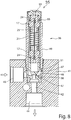
- FIG. 4 is an alternative embodiment to FIG. 3 shown, which is not part of the invention.
- This embodiment differs from that in FIG. 3 to the effect that the actuating element 25 is directly energized.
- a heating element 31 is not provided.
- the restoring element 21 is designed as a tension spring, since a pressure force is exerted by the adjusting element 25 on the connection elements 17 during energization. So that the drive device 11 is formed as a manageable module, the connecting pieces 17 are fixedly connected to the respective ends of the return element 21. This can be done for example by a screw, gluing, clamping or the like.
- FIG. 5 is another alternative embodiment too FIG. 1 shown. This embodiment differs from that in FIG FIG.
- the return element 21 is formed instead of a coil spring as a bellows element.
- a bellows element can completely shield the control element 25 from the environment.
- the bellows element can also have perforations, so that a gaseous or liquid medium can flow through the bellows element.
- FIG. 6 is an alternative embodiment to FIG. 1 shown.
- This embodiment differs only in that the adjusting element 25 is surrounded by a sleeve 58 which extends between the two connecting elements 17.
- an annular collar 60 is provided on each connecting element 17, through which a cup-shaped receiving area is created.
- the restoring element 21 which is designed as a compression spring
- the connecting elements 17 are positioned at a maximum distance which is determined by the length of the adjusting element 25 and the clamping elements 24 acting thereon.
- the length of the shell 58 is smaller than a length of the adjusting element 25 between the respective end faces 61 of the connecting elements 17 in a current-fed state of the actuating element 25. In energized or activated state of the actuating element 25 whose length is shortened.
- the shell 58 may for example be formed from a thermoplastic material or an elastomer, wherein the inner diameter is greater than the outer diameter of the actuating element 25, so that between the Control element 25 and the shell 58 an insulating layer can be formed.
- This insulating layer is dependent on the medium which is used. This may be water, oil, gel, refrigerant, coolant or the like.
- FIG. 7 is an alternative embodiment to FIG. 2 shown.
- a deflecting element 62 for example a pin, is provided, for example, on the left-hand connection element 17, which allows the deflection of the adjusting element 25, so that with an electrical connection two adjusting elements 25 arranged between the connection elements 17 can be actuated.
- a deflection of an actuating element 25 and / or a multiple deflection may be provided on each connecting element 17.
- FIG. 8 is a schematic sectional view of a switching valve 35 is shown, in which a drive 36 for controlling an opening and closing movement of a valve closing member 37 relative to a valve seat 38 with the drive means 11, for example according to FIG. 1 , he follows.
- a drive 36 for controlling an opening and closing movement of a valve closing member 37 relative to a valve seat 38 with the drive means 11, for example according to FIG. 1 he follows.
- it is a so-called NC switching valve (Normally Closed-switching valve).
- NC switching valve Normally Closed-switching valve
- the further embodiments of the drive device 11 may also be provided.
- This switching valve 35 comprises a housing 41 with a passage opening 42, which connects a feed opening 43 with an outlet opening 44.
- the supply port 43 and discharge port 44 are formed as terminals for mounting connection lines or piping.
- the passage opening 42 has a regulating chamber 46 in which, for example, a valve seat element 47 can be inserted with the valve seat 38.
- the valve seat 38 may be provided directly on the housing 41.
- the valve seat elements 47 it is made possible for the valve seat elements 47 to comprise passages of different sizes, so that a corresponding adaptation to the mass flow of the liquid or gaseous medium to be regulated is made possible.
- the drive 36 is preferably designed as an installation cartridge and into the regulating chamber 46 at least partially usable.
- the drive device 11 is provided within the sleeve-shaped housing 49.
- the valve closing member 37 is attached at a valve seat 38 facing connecting element 17, the valve closing member 37 is attached. This can be formed for example by screwing, pressing or the like.
- a closure element 53 which on the one hand firmly receives the connection element 17 and on the other hand sealingly closes the sleeve-shaped housing 49.
- a further seal 55 is provided.
- this switching valve 36 is formed as a thermostatic valve. As soon as the medium present at the feed opening 43 and in the regulating chamber 46 exceeds a switching temperature of the actuating element 25, the actuating element 25 is activated. The actuating force of the actuating element 25 is greater than the restoring force of the restoring element 21. As a result, the valve closing member 37 is lifted from the valve seat 38, and the mass flow can reach the outlet opening 44 and thus into the circuit. As soon as the temperature of the medium in the regulating chamber 46 and the adjusting element 25 drops, a closing movement of the valve closing member 37 is initiated.
- Such an embodiment of a switching valve may also be designed as a safety switching valve.
- the switching valve 35 be provided with a connecting line 12, so that via a control device 14, the adjusting movement of the valve closing member 37 by energizing the control element 25 is specifically or additionally controlled and / or the actuator is interrogated as a sensor.
- a control for example, a direct switching, electrically activated expansion valve can be formed in air conditioning circuits.
- this embodiment can be used as an expansion valve combined switching valve used in air conditioning circuits.
- such a switching valve can be used as a control or bypass valve and selectively controlled.
- This embodiment of the switching valve 35 which is electrically controllable, has the advantage over conventional expansion valves that they operate silently and, moreover, can have a small design. In addition, no electromagnetic drive is needed. In addition, can be dispensed with a motion drive, such as a thermal head with a gas filling.
Description
Die Erfindung betrifft eine Antriebseinrichtung zur Erzeugung einer Stellbewegung sowie ein Verfahren zur Ansteuerung einer solchen Antriebseinrichtung.The invention relates to a drive device for generating an actuating movement and to a method for controlling such a drive device.
Aus der
Eine analoge Anordnung ist aus der
Die
Aus der
Solche Linearbewegungsaktuatoren haben sich im Einsatz bewährt, jedoch sind die Anwendungs- und Einsatzfälle aufgrund dessen Bauform beschränkt.Such Linearbewegungsaktuatoren have proven themselves in use, however, the applications and applications are limited due to its design.
Aus der
Aus der
Aus der
Aus der
Aus der
Aus der
Aus der
Anpassung im Aufbau und der Anordnung für die Anwendung.Adaptation in construction and arrangement for the application.
Der Erfindung liegt die Aufgabe zugrunde, eine Antriebseinrichtung sowie ein Verfahren zur Ansteuerung der Antriebseinrichtung vorzuschlagen, welche vielfältig einsetzbar und modular aufbaubar ist.The invention has for its object to provide a drive device and a method for controlling the drive device, which is versatile and modular in structure.
Diese Aufgabe wird durch eine Antriebseinrichtung zur Erzeugung einer Stellbewegung gelöst, bei welcher das zumindest eine Stellelement zwischen zwei getrennt voneinander und im Abstand zueinander angeordneten Anschlusselementen aufgenommen ist und an jedem Anschlusselement angreift oder befestigt ist, wobei die Anschlusselemente durch das zumindest eine Stellelement sowie das zumindest eine Rückstellelement, die zwischen den Anschlusselementen positioniert und auf Abstand gehalten und durch deren entgegen gesetzte Wirkrichtungen die Anschlusselemente in einer definierten Ausgangslage für die Ansteuerung einer Stellbewegung positioniert sind und das Stellelement mit zumindest einem Klemmelement in einer Durchgangsbohrung des Anschlusselements gehalten oder einfach umgelenkt ist. Aufgrund dieser Anordnung der Anschlusselemente, des zumindest einen Stellelementes und des zumindest einen Rückstellelementes kann die Antriebseinrichtung eine Grundposition oder eine standardisierte Einbaugröße einnehmen. Auch nach einer Ansteuerung beziehungsweise Aktivierung der Antriebseinrichtung kehrt diese wieder selbständig in die Ausgangsposition mit der vorbestimmten Ausgangslänge zurück. Das zumindest eine Stellelement und das zumindest eine Rückstellelement sind koaxial zueinander positioniert und greifen jeweils an einem Anschlusselement an. Dadurch kann eine platzsparende und bauraumsparende Anordnung geschaffen sein. Diese Antriebseinrichtung ist auch vielseitig einsetzbar, indem am jeweiligen Anschlusselement ein weiteres Bauteil, Anschlussstück, Trägerelement oder dergleichen befestigt wird.This object is achieved by a drive device for generating an adjusting movement, in which the at least one adjusting element between two separate and spaced apart connection elements is received and engages or attached to each connection element, wherein the connection elements by at least one actuating element and the at least a reset element which is positioned between the connection elements and kept at a distance and positioned by the opposite directions of action, the connection elements in a defined starting position for the control of an actuating movement and the control element is held with at least one clamping element in a through hole of the connecting element or simply deflected. Due to this arrangement of the connecting elements, the at least one adjusting element and the at least one return element, the drive device can assume a basic position or a standardized mounting size. Even after a control or activation of the drive device, this returns automatically back to the starting position with the predetermined output length. The at least one adjusting element and the at least one return element are positioned coaxially with each other and each engage a connecting element. This can be created a space-saving and space-saving arrangement. This drive device is also versatile in that a further component, connector, support member or the like is attached to the respective connection element.
Die Anschlusselemente, das zumindest eine Stellelement und das zumindest eine Rückstellelement sind als ein handhabbares Modul ausgebildet. Durch die Anordnung des Stellelementes und des Rückstellelementes zwischen den Anschlussstücken und deren entgegen gesetzten Wirkrichtungen können diese Einzelbauteile als eine Baugruppe oder ein Modul selbständig zusammengehalten werden, so dass eine Vormontage eines solchen Moduls möglich ist und das aus diesen Bauteilen zusammen gesetzte Modul als einsatzfähige Einheit vorliegt.The connecting elements, the at least one adjusting element and the at least one return element are formed as a manageable module. By arranging the actuating element and the restoring element between the connecting pieces and their opposite directions of action, these individual components can be held together as an assembly or a module independently, so that a pre-assembly of such a module is possible and the module composed of these components is present as a usable unit ,
Eine weitere bevorzugte Ausgestaltung der Erfindung sieht vor, dass an dem zumindest einen Stellelement eine elektrische Anschlussleitung anschließbar ist, welche vorzugsweise mit einer Steuereinrichtung verbunden ist.A further preferred embodiment of the invention provides that an electrical connection line can be connected to the at least one adjusting element, which is preferably connected to a control device.
An dem zumindest einen Stellelement ist bevorzugt eine elektrische Anschlussleitung anschließbar ist, welche insbesondere mit einer Steuereinrichtung verbunden sein kann. Dadurch kann mittels der anschließbaren Steuereinrichtung über die Anschlussleitung sowohl eine aktive Ansteuerung des zumindest einen Stellelementes zur Erzeugung einer Stellbewegung erzielt werden, als auch eine Sensorfunktion gegeben sein, welche wiederum durch die Steuereinrichtung erfassbar ist. Durch die an das Stellelement anschließbare Anschlussleitung kann die Antriebseinrichtung auch ohne Anschlussleitung als Sensor und/oder Stellelement eingesetzt werden, welches in Abhängigkeit einer auf das Stellelement wirkenden Umgebungstemperatur aktiviert und betätigt wird.On the at least one adjusting element, preferably an electrical connection line can be connected, which can be connected in particular to a control device. As a result, by means of the connectable control device via the connecting line both an active control of the at least one adjusting element for generating an actuating movement can be achieved, as well as a sensor function be given, which in turn can be detected by the control device. By connectable to the actuator connection line, the drive device can be used without a connecting line as a sensor and / or actuator, which is activated and operated in response to an acting on the actuator ambient temperature.
Des Weiteren ist bevorzugt vorgesehen, dass das Rückstellelement als Federelement oder Balgelement ausgebildet ist. Somit kann eine einfache und kostengünstige Ausgestaltung als auch eine einfache Aufnahme mittels der Anschlusselemente ermöglicht sein.Furthermore, it is preferably provided that the restoring element is designed as a spring element or bellows element. Thus, a simple and cost-effective design as well as a simple recording by means of the connection elements can be made possible.
Bevorzugt weist das Anschlusselement einen Längsschlitz auf, der zur Durchgangsbohrung führt, so dass ein einfaches Einsetzen des Stellelemente an den beiden Anschlusselementen ermöglicht ist. Somit kann eine Montage ohne zusätzliches Werkzeug erfolgen. Aufgrund des dazwischen angeordneten Rückstellelementes werden die Bauteile der Antriebseinrichtung, also die Anschlusselemente, das Stellelement mit den daran angeordneten Klemmelementen und die Rückstellfeder in einer festen Ausgangsposition zueinander angeordnet gehalten.Preferably, the connection element has a longitudinal slot, which leads to the through hole, so that a simple insertion of the adjusting elements is made possible on the two connection elements. Thus, a mounting can be done without additional tools. Due to the restoring element arranged therebetween, the components of the drive device, ie the connecting elements, the adjusting element with the clamping elements arranged thereon and the return spring are held in a fixed starting position to each other.
Vorzugsweise kann ein Ende des Stellelementes durch ein Klemmelement oder einem Stift in einem Anschlusselement umgelenkt werden, so dass in einem gegenüber liegenden Anschlusselement zwei Enden des Stellelementes durch das Klemmelement befestigt sind. Dadurch kann eine Verdoppelung der Stellkraft erzielt werden. Es ist ebenso möglich, eine Mehrfachumlenkung vorzusehen, welche flaschenzugförmig zwischen den Anschlusselementen verläuft.Preferably, one end of the adjusting element can be deflected by a clamping element or a pin in a connecting element, so that two ends of the adjusting element are fastened by the clamping element in an opposite connecting element. As a result, a doubling of the actuating force can be achieved. It is also possible to provide a multiple deflection, which runs flaschenzugförmig between the connection elements.
Das zumindest eine Stellelement aus einer Formgedächtnislegierung ist bevorzugt als ein länglicher Draht ausgebildet. Dies stellt eine sehr einfache Ausführungsform dar. Alternativ kann das Stellelement auch als Rohr oder als Spiralfederelement ausgebildet sein.The at least one actuator made of a shape memory alloy is preferably formed as an elongated wire. This represents a very simple embodiment. Alternatively, the adjusting element can also be designed as a tube or as a spiral spring element.
Vorzugsweise ist das Stellelement mit einer Hülle umgeben. Dadurch kann ein verbessertes Ansprechverhalten des Stellelementes erzielt werden.Preferably, the actuator is surrounded by a shell. As a result, an improved response of the control element can be achieved.
Eine weitere alternative Ausgestaltung der Erfindung sieht vor, dass an dem Anschlusselement ein Heizelement, insbesondere PTC-Element, vorgesehen ist, welches sich zum gegenüberliegenden Anschlusselement erstreckt und von einem spiralförmigen Stellelement umgeben ist. Diese Ausführungsform kann besonders für weitere Einsatzfälle geeignet sein.A further alternative embodiment of the invention provides that a heating element, in particular a PTC element, is provided on the connection element, which is located to the opposite connection element extends and is surrounded by a helical actuator. This embodiment may be particularly suitable for other applications.
Jedes Anschlusselement umfasst einen Montageabschnitt. Dadurch sind Anschlüsse für einen schnellen Einbau der jeweiligen Einsatzzwecke ermöglicht.Each connection element comprises a mounting section. As a result, connections for a quick installation of the respective purposes are possible.
Nach einer weiteren alternativen Ausführungsform der Erfindung ist vorgesehen, dass zumindest zwei Stellelemente vorgesehen sind, welche gleiche oder voneinander abweichende Arbeitsbereiche oder Schalttemperaturen aufweisen. Bei abweichenden Arbeitsbereichen der Stellelemente kann eine mehrstufige Regelung oder Ansteuerung gegeben sein. Bei mehreren Stellelementen mit gleichen Arbeitsbereichen kann eine Kraft- oder Wegverstärkung erfolgen.According to a further alternative embodiment of the invention it is provided that at least two adjusting elements are provided, which have the same or different working ranges or switching temperatures. In different working areas of the control elements, a multi-level control or control can be given. With several actuators with the same work areas can be a force or Wegverstärkung.
Die Stellbewegung des zumindest einen Stellelementes kann mit der Steuerungseinrichtung ansteuerbar sein. Dadurch kann beispielsweise eine Zweipunktregelung oder eine Proportionalregelung erfolgen. Eine definierte Ansteuerung des Stellelementes kann durch eine entsprechende Bestromung ermöglicht werden, wodurch gleichzeitig auch durch die Steuerungseinrichtung eine Positionsbestimmung des beweglichen Anschlusselementes gegeben sein kann. Somit ist die Stellbewegung des Stellelementes kontrollierbar und überwachbar.The adjusting movement of the at least one adjusting element can be controlled by the control device. This can be done, for example, a two-step control or a proportional control. A defined control of the control element can be made possible by a corresponding energization, whereby at the same time can be given by the control device, a position determination of the movable connection element. Thus, the adjusting movement of the actuating element is controllable and monitorable.
Alternativ kann vorgesehen sein, dass ein elektrischer Widerstand des zumindest einen Stellelementes mit der Steuereinrichtung erfassbar ist. Dadurch kann beispielsweise auch eine Diagnose über den Ermüdungszustand des Stellelementes oder ein Istwert von der das Stellelement umgebenden Mediumstemperatur erfasst und ausgewertet werden. Eine solche Erfassung von Daten kann zu Steuerungsdiagnose oder Dokumentationszwecke erfolgen.Alternatively it can be provided that an electrical resistance of the at least one actuating element can be detected by the control device. As a result, it is also possible, for example, to record and evaluate a diagnosis of the state of fatigue of the control element or an actual value of the medium temperature surrounding the control element. Such collection of data may be for control diagnosis or documentation purposes.
Die der Erfindung zugrunde liegende Aufgabe wird des Weiteren durch ein Verfahren zur Ansteuerung von der Antriebseinrichtung gelöst, bei der ein Widerstand des zumindest einen Stellelementes von der Steuerungseinrichtung erfasst und/oder das zumindest eine Stellelement zur Erzeugung einer Stellbewegung an der Steuerungseinrichtung mit der Steuerungseinrichtung bestromt. Dadurch ist die Antriebseinrichtung sowohl als Aktor zur Erzeugung einer Stellbewegung sowie als Sensor zur Erfassung des Arbeitszustandes des Stellelementes möglich, wobei insbesondere die sensorische Funktion für die Auswertung und/oder Überwachung der Stellbewegung und/oder des Zustandes des zumindest einen Stellelementes zu Dokumentationszwecken vorgesehen ist.The object on which the invention is based is furthermore achieved by a method for controlling the drive device, in which a resistance of the at least one control element is detected by the control device and / or the at least one control element is energized by the control device to generate an actuating movement on the control device. This is the drive device both as an actuator for generating an actuating movement and as a sensor for detecting the operating state of the actuating element possible, in particular the sensory function for the evaluation and / or monitoring of the adjusting movement and / or the state of the at least one actuating element is provided for documentation purposes.
Die Antriebseinrichtung zur Erzeugung einer Stellbewegung gemäß der Erfindung ist als Antrieb für ein Schaltventil für flüssige oder gasförmige Medien vorgesehen, wobei an einem Anschlusselement der Antriebseinrichtung ein Ventilschließglied anordenbar ist, welches einen Ventilsitz an einer Durchgangsöffnung in einem Ventilgehäuse öffnet und schließt. Durch das Stellelement kann eine durch die Temperatur des Mediums erfolgende Stellbewegung des Ventilschließgliedes zum Öffnen und Schließen des Ventilsitzes ansteuerbar sein, so dass dieses Schaltventil entweder geöffnet oder geschlossen ist. Des Weiteren kann durch eine solche Antriebseinrichtung ein gezieltes Öffnen und Schließen zu einem voreinstellbaren Schaltpunkt vorgesehen sein. Sofern eine Steuerungseinrichtung an die Antriebssteuerung angeschlossen ist, kann die Öffnungs- und Schließbewegung derart ansteuerbar sein, dass eine kontinuierliche, degressive oder progressive Freigabe der Durchtrittsöffnung am Ventilsitz ermöglicht wird.The drive device for generating an actuating movement according to the invention is provided as a drive for a switching valve for liquid or gaseous media, wherein on a connecting element of the drive means, a valve closing member can be arranged, which opens and closes a valve seat at a passage opening in a valve housing. By means of the adjusting element, an adjusting movement of the valve closing member taking place through the temperature of the medium can be actuated for opening and closing the valve seat, so that this switching valve is either open or closed. Furthermore, a targeted opening and closing to a presettable switching point can be provided by such a drive means. If a control device is connected to the drive control, the opening and closing movement can be controlled such that a continuous, degressive or progressive release of the passage opening is made possible on the valve seat.
Bevorzugt ist beim Schaltventil vorgesehen, dass die Antriebseinrichtung in einem hülsenförmigen Gehäuse vorgesehen ist, welche vorzugsweise mit einem Anschlusselement fest verbindbar ist. Dadurch kann eine einfache Montage des Antriebs zum Ventilgehäuse ermöglicht sein.Preferably, it is provided in the switching valve that the drive device is provided in a sleeve-shaped housing, which is preferably firmly connected to a connection element. As a result, a simple assembly of the drive to the valve housing can be made possible.
Das Schaltventil weist bevorzugt an einem dem Ventil gegenüber liegenden Ende des hülsenförmigen Gehäuses ein Verschlusselement auf, welches das hülsenförmige Ende mediendicht verschließt und eine Anschlussleitung nach außen führt. Dadurch kann ein konstruktiv einfacher Aufbau mit einem abdichtenden Ende des Gehäuses, an welchem die Antriebseinrichtung vorgesehen ist, ausgebildet werden. Gleichzeitig kann die Anschlussleitung zur Ansteuerung des zumindest einen Stellelementes in einfacher Form herausgeführt und mit einer Steuereinrichtung verbunden werden.The switching valve preferably has at a valve opposite the end of the sleeve-shaped housing a closure element, which closes the sleeve-shaped end media-tight and leads a connecting line to the outside. This allows a structurally simple construction with a sealing end of the housing, on which the drive device is provided, are formed. At the same time, the connecting line for driving the at least one adjusting element can be led out in a simple form and connected to a control device.
Das hülsenförmige Gehäuse, in welchem die Antriebseinrichtung aufgenommen ist, wird bevorzugt als Einschraubelement ausgebildet, so dass dieses in das Ventilgehäuse einsetzbar ist. Dadurch kann eine schnelle Komplettierung eines solchen Schaltventils ermöglicht sein.The sleeve-shaped housing, in which the drive device is accommodated, is preferably designed as a screw-in element, so that it can be inserted into the valve housing. As a result, a quick completion of such a switching valve can be made possible.
Bevorzugt ist vorgesehen, dass in einer Durchtrittsöffnung im Ventilgehäuse ein Ventilsitzelement einsetzbar ist. Dadurch kann eine variable Anpassung an verschiedene Einsatzfälle des Schaltventils ermöglicht sein, indem der Ventilsitz, welcher in das Ventilgehäuse einsetzbar ist, sowie das Ventilschließglied, welches mit einem Anschlusselement austauschbar vorgesehen ist, ausgewählt werden.It is preferably provided that a valve seat element can be inserted in a passage opening in the valve housing. Thereby, a variable adaptation to different applications of the switching valve can be made possible by the valve seat, which is insertable into the valve housing, as well as the valve closing member, which is provided with a connection element interchangeable selected.
Das Schaltventil kann bevorzugt als Expansionsventil in Klimakreisläufen eingesetzt werden. Insbesondere kann dieses Schaltventil als direkt schaltendes elektrisch aktiviertes Expansionsventil in Klimakreisläufe verwendet werden.The switching valve may preferably be used as an expansion valve in air conditioning circuits. In particular, this switching valve can be used as a direct-switching electrically activated expansion valve in air conditioning circuits.
Alternativ kann das erfindungsgemäße Schaltventil als Thermostatventil in Klimakreisläufen oder Heizkreisläufen eingesetzt werden. Insbesondere in stationären Heizkreisläufen kann ein solches Schaltventil für Regel-, Sicherheits- oder Bypass-Schaltungen verwendet werden.Alternatively, the switching valve according to the invention can be used as a thermostatic valve in air conditioning circuits or heating circuits. In particular, in stationary heating circuits, such a switching valve for control, safety or bypass circuits can be used.
Darüber hinaus kann das Schaltventil in Übergabestationen, wie beispielsweise der Warmwasseraufbereitung, durch einen Heizkreislauf, eingesetzt werden. Darüber hinaus kann das Schaltventil in Trinkwassersystemen, beispielsweise zur Legionellenschaltung oder Desinfektionsschaltung verwendet werden.In addition, the switching valve can be used in transfer stations, such as the hot water treatment, by a heating circuit. In addition, the switching valve can be used in drinking water systems, for example, Legionellenschaltung or disinfection circuit.
Die Erfindung sowie weitere vorteilhafte Ausführungsformen und Weiterbildungen derselben werden im Folgenden anhand der in den Zeichnungen dargestellten Beispiele näher beschrieben und erläutert. Die der Beschreibung und den Zeichnungen zu entnehmenden Merkmale können einzeln für sich oder zu mehreren in beliebiger Kombination erfindungsgemäß angewandt werden. Es zeigen:
-
Figur 1 eine schematische Schnittansicht der erfindungsgemäßen Antriebseinrichtung, -
Figur 2 eine schematische Schnittansicht einer alternativen Ausführungsform zuFigur 1 , -
Figur 3 eine schematische Schnittansicht einer weiteren alternativen Ausführungsform zuFigur 1 , die nicht Teil der Erfindung ist, -
Figur 4 eine schematische Schnittansicht einer weiteren alternativen Ausführungsform zuFigur 3 , die nicht Teil der Erfindung ist, -
Figur 5 eine schematische Schnittansicht einer weiteren alternativen Ausführungsform zuFigur 1 , -
Figur 6 eine schematische Schnittansicht einer weiteren alternativen Ausführungsform zuFigur 1 , -
Figur 7 eine schematische Schnittansicht einer weiteren alternativen Ausführungsform zuFigur 2 und -
Figur 8 eine schematische Schnittdarstellung der Antriebseinrichtung in der Anwendung als Schaltventil.
-
FIG. 1 a schematic sectional view of the drive device according to the invention, -
FIG. 2 a schematic sectional view of an alternative embodiment toFIG. 1 . -
FIG. 3 a schematic sectional view of another alternative embodiment toFIG. 1 that is not part of the invention, -
FIG. 4 a schematic sectional view of another alternative embodiment toFIG. 3 that is not part of the invention, -
FIG. 5 a schematic sectional view of another alternative embodiment toFIG. 1 . -
FIG. 6 a schematic sectional view of another alternative embodiment toFIG. 1 . -
FIG. 7 a schematic sectional view of another alternative embodiment toFIG. 2 and -
FIG. 8 a schematic sectional view of the drive device in the application as a switching valve.
In
Die Antriebseinrichtung 11 umfasst zwei Anschlusselemente 17, welche getrennt zueinander angeordnet sind. Die Anschlusselemente 17 sind vorteilhafterweise zylindrisch ausgebildet und weisen einen ersten Anschlussabschnitt 19 zur Aufnahme eines Rückstellelementes 21 auf, welches gemäß einer ersten Ausführungsform als Spiralfeder ausgebildet ist. Das erste Anschlussabschnitt 19 bildet für die jeweiligen Enden des Rückstellelementes 21 eine Aufnahme und zumindest eine zumindest geringfügige Führung.The
Die Anschlusselemente 17 weisen jeweils eine zentrale, vorzugsweise gestufte, Durchgangsbohrung 23 auf. Mittels Klemmelementen 24 ist ein Stellelement 25 in den Durchgangsbohrungen 23 der Anschlusselemente 17 fixiert gehalten. Durch die Klemmelemente 24 kann der Abstand der Anschlusselemente 17 bestimmt sein oder eingestellt werden, wobei die Anschlusselemente 17 aufgrund des Rückstellelementes 21 auf Abstand und somit das Stellelement 25 unter zumindest geringfügiger Spannung gehalten ist. Das Rückstellelement 21 ist bei dieser Ausführungsform als Druckfeder ausgelegt. Die Anschlusselemente 17 weisen vorteilhafterweise einen Längsschlitz auf, der sich vom Außenumfang des Anschlusselementes 17 bis zur Durchgangsbohrung 23 erstreckt. Dadurch können die Klemmelemente 24 vor dem Einbau des Stellelementes 25 in einfacher Weise daran fixiert werden, wobei anschließend eine einfache Montage der Bauteile zueinander ermöglicht ist. Bspw. wird ein Klemmelement 24 in ein Anschlusselement 17 eingesetzt, so dass diese in der gestuften Durchgangsbohrung 23 angreift. Anschließend wird das Rückstellelement 21 auf das Anschlusselement 17 aufgesetzt, bevor das gegenüberliegende Anschlusselement 17 zum Rückstellelement 21 positioniert wird und das gegenüberliegende Ende des Stellelementes 24 in die Durchgangsbohrung 23 des Anschlusselementes 17 über dessen Längsnut eingesetzt wird. Durch einen solchen Aufbau und Anordnung ist nach dem Zusammenbau der Komponenten die Antriebseinrichtung 11 als ein handhabbares Modul beziehungsweise als eigenstände Baugruppe ausgebildet.The connecting
Das Stellelement 25 besteht aus einer Formgedächtnislegierung (beispielsweise aus einer NiTi-Legierung, aus einer Legierung aus Cu-Basis oder Fe-Basis oder aus Memory-Kunststoff). In Abhängigkeit des Einsatzfalles können unterschiedliche Arbeitspunkte beziehungsweise Schalttemperaturen eingestellt werden. Im ersten Ausführungsbeispiel ist das Stellelement 25 als Draht ausgebildet.The
Das eine Anschlusselement 17 beziehungsweise das rechte Anschlusselement 17 weist einen Montageabschnitt 27 auf, an welchem beispielsweise ein Ventilschließglied oder andere Bauteile befestigbar sind. Das gegenüber liegende Anschlusselement 17 weist einen Montageabschnitt und/oder einen Dichtabschnitt 28 auf, um die Antriebseinrichtung 11 in einem weiteren Gehäuse oder Gehäuseabschnitt aufzunehmen oder an einem Einbauort zu befestigen.The one
Bei dieser Ausführungsform nach der Erfindung umgibt das Rückstellelement 21 koaxial das Stellelement 25, so dass eine zylindrische Bauform der Antriebseinrichtung 11 gegeben ist. Die Anschlusselemente 17 können aus Kunststoff oder Metall ausgebildet sein.In this embodiment according to the invention, the
Alternativ kann des Weiteren vorgesehen sein, dass das Rückstellelement 21 ebenfalls aus einer Formgedächtnislegierung ausgebildet ist.Alternatively, it can further be provided that the restoring
An einem Ende des Stellelementes 25 ist die Anschlussleitung 12 anschließbar. Die Antriebseinrichtung 11 kann mittels der Steuereinrichtung 14 das Stellelement ansteuern, indem das Stellelement 25 bestromt wird. Dadurch zieht sich das Stellelement 25 zusammen, so dass die beiden Anschlusselemente 17 aufeinander zubewegt werden beziehungsweise soweit eines der beiden Anschlusselemente 17 fest eingespannt ist, wird das gegenüber liegende aktiv auf das feststehende oder fest eingespannte Anschlusselement 17 zubewegt. Sobald über die Steuerungseinrichtung 14 eine Bestromung abgeschaltet wird, erfolgt eine Rückstellung der Antriebseinrichtung 11 durch das Rückstellelement 21, dessen Druckkraft dann überwiegt.At one end of the
Alternativ kann vorgesehen sein, dass das Stellelement 25 durch ein gasförmiges oder flüssiges Medium umgeben und durch dessen Temperatur angesteuert wird. Sobald eine Temperaturüberschreitung des gasförmigen oder flüssigen Mediums erfolgt, kommt es zu einer Stellbewegung des einen Anschlusselementes 17. Wird das Stellelement 25 aktiviert und eine Steuerungseinrichtung 14 ist angeschlossen, kann über die Steuerungseinrichtung 14 eine Änderung des Widerstandes erfasst werden, um somit diesen Zustand des Stellelementes 25 zu erfassen. Gleichzeitig kann dadurch eine Auswertung der Antriebseinrichtung 11 gegeben sein. In diesem Fall kann die Antriebseinrichtung 11 für eine thermische Regelung eingesetzt werden. Zusätzlich kann zur Temperaturerfassung des flüssigen oder gasförmigen Mediums noch eine aktive Ansteuerung über die Steuerungseinrichtung 14 erfolgen.Alternatively, it can be provided that the adjusting
In
Bevorzugt ist vorgesehen, dass diese voneinander abweichende Schaltpunkte aufweisen, so dass eine zweistufige Stellbewegung der Antriebseinrichtung 11 mittels der Steuerungseinrichtung 14 ansteuerbar ist.It is preferably provided that they have mutually differing switching points, so that a two-stage adjusting movement of the
Bei dieser Ausführungsform gemäß
Es versteht sich, dass alternativ zu zwei Stellelementen 25 auch mehrere Stellelemente mit gleichen oder unterschiedlichen Schaltpunkten vorhanden sein können.It is understood that as an alternative to two
In
In
In
In
In
Dieses Schaltventil 35 umfasst ein Gehäuse 41 mit einer Durchtrittsöffnung 42, welche eine Zuführöffnung 43 mit einer Auslassöffnung 44 verbindet. Die Zuführöffnung 43 und Auslassöffnung 44 sind als Anschlüsse zur Montage von Anschlussleitungen oder einer Verrohrung ausgebildet. Die Durchtrittsöffnung 42 weist einen Regulierraum 46 auf, in dem beispielsweise ein Ventilsitzelement 47 mit dem Ventilsitz 38 einsetzbar ist. Alternativ kann der Ventilsitz 38 unmittelbar an dem Gehäuse 41 vorgesehen sein. Bei dieser gestellten Ausführungsform ist ermöglicht, dass die Ventilsitzelemente 47 unterschiedlich große Durchgangsbohrungen umfassen, so dass dadurch eine entsprechende Anpassung an den zu regulierenden Massenstrom des flüssigen oder gasförmigen Mediums ermöglicht ist. Der Antrieb 36 ist bevorzugt als Einbaupatrone ausgebildet und in den Regulierraum 46 zumindest teilweise einsetzbar. Dieser weist vorteilhafterweise ein hülsenförmiges Gehäuse 49 auf, welches mit dem Regulierraum 46 verschraubbar ist, wobei vorzugsweise dazwischen liegend eine Dichtung 51 vorgesehen ist, um den Antrieb 36 zum Gehäuse 41 abzudichten. Innerhalb des hülsenförmigen Gehäuses 49 ist die Antriebseinrichtung 11 vorgesehen. An einem zum Ventilsitz 38 weisenden Anschlusselement 17 ist das Ventilschließglied 37 befestigt. Dies kann beispielsweise durch Aufschrauben, Aufpressen oder dergleichen ausgebildet werden. Gegenüber liegend greift an dem zweiten Anschlusselement 17 ein Verschlusselement 53 an, welches einerseits das Anschlusselement 17 fest aufnimmt und andererseits das hülsenförmige Gehäuse 49 dichtend abschließt. Vorteilhafterweise ist eine weitere Dichtung 55 vorgesehen.This switching
Gemäß einer ersten Ausführungsform kann vorgesehen sein, dass dieses Schaltventil 36 als Thermostatventil ausgebildet ist. Sobald das an der Zuführöffnung 43 und im Regulierraum 46 anliegende Medium eine Schalttemperatur des Stellelementes 25 übersteigt, wird das Stellelement 25 aktiviert. Die Stellkraft des Stellelementes 25 ist größer als die Rückstellkraft des Rückstellelementes 21. Dadurch wird das Ventilschließglied 37 von dem Ventilsitz 38 abgehoben, und der Massenstrom kann zur Ausgangsöffnung 44 und somit in den Kreislauf gelangen. Sobald die Temperatur des Mediums im Regulierraum 46 und am Stellelement 25 sinkt, wird eine Schließbewegung des Ventilschließgliedes 37 eingeleitet.According to a first embodiment it can be provided that this switching
Ein solches Ausführungsbeispiel eines Schaltventils kann auch als ein Sicherheitsschaltventil ausgebildet sein.Such an embodiment of a switching valve may also be designed as a safety switching valve.
Alternativ kann das Schaltventil 35 gemäß
Des Weiteren kann bei einem solchen Schaltventil 35 mit einer Steuerungseinrichtung 14 eine Überwachung des Schaltzeitpunkts für ein Öffnen oder Schließen des Ventils erfasst und überwacht werden.Furthermore, with such a
Diese Ausführungsform des Schaltventils 35, welches elektrisch ansteuerbar ist, weist gegenüber herkömmlichen Expansionsventilen den Vorteil auf, dass diese geräuschlos arbeiten und darüber hinaus eine kleine Bauform aufweisen können. Darüber hinaus wird kein elektromagnetischer Antrieb benötigt. Darüber hinaus kann auch auf einen Bewegungsantrieb, wie beispielsweise einen Thermokopf mit einer Gasfüllung verzichtet werden.This embodiment of the switching
Alle vorgenannten Merkmale sind jeweils für sich erfindungswesentlich und können beliebig miteinander kombinierbar sein.All of the aforementioned features are essential to the invention and can be combined with one another as desired.
Claims (12)
- Drive device for the generation of an actuation movement, having at least one actuation element (25) made from a memory shape alloy, having at least one resetting element (21) which counteracts the actuation movement of the at least one actuation element (25), and the at least one actuation element (25) is received between two connection elements (17) that are arranged separately from each other and with spacing apart from each other and engages with or is fastened to each connection element (17), the connection elements (17) are held at a distance by the at least one actuation element (25) and the at least one resetting element (21), which are positioned between the connection elements (17), and, as a result of the opposing directions of action thereof, the connection elements (17) are positioned in a defined starting position for controlling an actuation movement, and the at least one actuation element (25) and the at least one resetting element (21) are positioned coaxially relative to each other,- wherein each connection element (17) comprises a first connection section (19) for guiding the at least one resetting element (21),- wherein the at least one actuation element (25)and the at least one resetting element (21) each engage with the connection elements (17) and the at least one resetting element (31) surrounds the actuation element (25),
characterized in- that the actuation element (25) is held with a clamping element (24) in a through bore (23) of the connection element (17) or is at least simply redirected,- each connection element (17) has an installation section (27) opposite to the connection section (19), and- the connection elements (17), the at least one actuation element (25) and the at least one resetting element (21) are formed as a manageable module. - Drive device according to claim 1, characterised in that an electrical connection line (12) is connectable to the at least one actuation element (25), said connection line preferably being connected to a control device (14), wherein an actuation movement of the at least one actuation element (25) is controllable with the control device (14), or an electrical resistance of the at least one actuation element (215) is registerable with the control device (14).
- Drive device according to claim 1, characterised in that the actuation element (25) is formed as an elongated wire, as a tube or as a spiral spring element, which is preferably surrounded by a cover (58) .
- Drive device according to claim 1, characterised in that a heating element, in particular a PTC element, is provided on a connection element (17), said heating element extending in the direction of the opposite connection element (17) and being surrounded at least by a spiral-shaped actuation element (25).
- Drive device according to claim 1, characterised in that at least one connection element (17) has an installation and/or sealed section (27, 28).
- Drive device according to claim 1, characterised in that at least two actuation elements (25) are provided, which have different operating ranges or switching points.
- Method for controlling the drive device (11) according to one of claims 1 to 6, characterised in that an electrical resistance of the actuation element (25) is registered on a control device (14) and/or the at least one actuation element (25) is fed with a current by the control device (14) for the generation of an actuation movement, and/or an actuation movement is controlled by an ambient temperature.
- Switching valve for liquid or gaseous media, having a housing (41) which has at least one passage opening (42) that connects a supply opening (43) to an outlet opening (44), having a valve seat (38) arranged in the passage opening (44), said valve seat being able to be closed by a valve closing member (37) that is controllable with a drive (36) which is arrangable on the housing (41), characterised in that the drive (36) has a drive device (11) according to one of claims 1 to 6 and the valve closing member (37) is arrangable on a connection element (17) of the drive device (11).
- witching valve according to claim 8, characterised in that the drive device (11) is provided in a sleeve-like housing (49) and is connectable fixedly to a connection element (17), and Switching valve according to claim 14, characterised in that a locking element (53) is provided on an end opposite the valve closing member (37), said locking element sealing the sleeve-like housing with media-tightness, in particular with a sealing element (55), and preferably guiding a connection line to the outside.
- Switching valve according to claim 9, characterised in that the sleeve-like housing (49) of the drive (36) is insertable into the housing (41) as a screw-in element.
- Switching valve according to claim 8, characterised in that a valve seat element (47) pointing towards the regulating space (46) is insertable into the passage opening (42).
- Use of the switching valve according to claim 8 to 11 as an expansion valve in air conditioning circuits, as a thermostat valve for air conditioning circuits or heating circuits, or as a switching valve in drinking water supply systems.
Applications Claiming Priority (2)
| Application Number | Priority Date | Filing Date | Title |
|---|---|---|---|
| DE102013010027.5A DE102013010027A1 (en) | 2013-06-17 | 2013-06-17 | Drive device and method for controlling the drive means for generating an actuating movement |
| PCT/EP2014/061099 WO2014202369A1 (en) | 2013-06-17 | 2014-05-28 | Drive device and a method for controlling said drive device in order to produce an actuation movement |
Publications (2)
| Publication Number | Publication Date |
|---|---|
| EP3011176A1 EP3011176A1 (en) | 2016-04-27 |
| EP3011176B1 true EP3011176B1 (en) | 2019-05-08 |
Family
ID=50877270
Family Applications (1)
| Application Number | Title | Priority Date | Filing Date |
|---|---|---|---|
| EP14727472.4A Active EP3011176B1 (en) | 2013-06-17 | 2014-05-28 | Drive device and a method for controlling said drive device in order to produce an actuation movement |
Country Status (4)
| Country | Link |
|---|---|
| US (1) | US10066756B2 (en) |
| EP (1) | EP3011176B1 (en) |
| DE (1) | DE102013010027A1 (en) |
| WO (1) | WO2014202369A1 (en) |
Families Citing this family (12)
| Publication number | Priority date | Publication date | Assignee | Title |
|---|---|---|---|---|
| FR3057611A1 (en) * | 2016-10-19 | 2018-04-20 | Faurecia Systemes D'echappement | ACTUATOR FOR A VALVE OF A DEVICE FOR RECOVERING HEAT FROM EXHAUST, IN PARTICULAR FROM A MOTOR VEHICLE |
| EP3343078A1 (en) * | 2016-12-29 | 2018-07-04 | L&P Property Management Company | Valve with shape memory alloy wire |
| CN109695703B (en) * | 2017-10-23 | 2021-02-02 | 浙江三花汽车零部件有限公司 | Heat exchange device |
| DE102018207393A1 (en) * | 2018-05-14 | 2019-11-14 | PFW Aerospace GmbH | Valve with at least one valve element |
| EP3715795A1 (en) * | 2019-03-29 | 2020-09-30 | Siemens Aktiengesellschaft | Positioning in a high pressure area |
| CN112824848B (en) * | 2019-11-21 | 2022-05-10 | 成都飞机工业(集团)有限责任公司 | Light ejection mechanism |
| EP3869074B1 (en) * | 2020-02-24 | 2023-06-21 | Schukra Berndorf GmbH | Electrically actuated valves |
| CN114584637B (en) * | 2020-11-28 | 2023-07-18 | 华为技术有限公司 | Shape memory alloy motor, motor module, camera module and electronic equipment |
| KR20220090966A (en) * | 2020-12-23 | 2022-06-30 | 엘지디스플레이 주식회사 | Variable curvature display device |
| US11808374B2 (en) | 2020-12-30 | 2023-11-07 | Leggett & Platt Canada Co. | Fluid management system |
| CN113483264B (en) * | 2021-07-29 | 2023-12-08 | 嘉兴艾迪西暖通科技有限公司 | Anti-filling valve |
| DE102022109609B3 (en) | 2022-04-21 | 2023-08-03 | Otto Egelhof Gmbh & Co. Kg | Valve for controlling a medium in a refrigeration or heating circuit |
Citations (4)
| Publication number | Priority date | Publication date | Assignee | Title |
|---|---|---|---|---|
| US5211371A (en) * | 1991-07-22 | 1993-05-18 | Advanced Control Technologies, Inc. | Linearly actuated valve |
| EP0841510A1 (en) * | 1996-11-08 | 1998-05-13 | Matsushita Electric Works, Ltd. | Flow control valve |
| EP1619287A1 (en) * | 2004-07-13 | 2006-01-25 | C.R.F. Società Consortile per Azioni | Household appliance, namely a machine for washing and/or drying laundry, with a door block/release device that can be actuated electrically |
| DE102006037650A1 (en) * | 2006-02-09 | 2007-08-16 | Otto Egelhof Gmbh & Co. Kg | Linear movement actuator has spring unit, designed as part of carrier device, mounted on actuator and has receiving section, which is mounted at housing section of linear movement actuator, which is transferred from basic to tax position |
Family Cites Families (20)
| Publication number | Priority date | Publication date | Assignee | Title |
|---|---|---|---|---|
| US3755876A (en) * | 1972-07-10 | 1973-09-04 | J Beasley | Method and apparatus for repairing valve seats |
| US4503878A (en) * | 1983-04-29 | 1985-03-12 | Cameron Iron Works, Inc. | Choke valve |
| JPH0229378U (en) * | 1988-08-12 | 1990-02-26 | ||
| US4973024A (en) * | 1989-09-26 | 1990-11-27 | Toki Corporation Kabushiki Kaisha | Valve driven by shape memory alloy |
| DE4322731A1 (en) * | 1993-07-08 | 1995-01-12 | Leybold Ag | Valve for regulating fluid flows with an actuator made of electrically heatable, shape-remembering material |
| US5816306A (en) * | 1993-11-22 | 1998-10-06 | Giacomel; Jeffrey A. | Shape memory alloy actuator |
| US6326707B1 (en) * | 2000-05-08 | 2001-12-04 | Mark A. Gummin | Shape memory alloy actuator |
| DE10233601A1 (en) * | 2002-07-24 | 2004-02-19 | Fraunhofer-Gesellschaft zur Förderung der angewandten Forschung e.V. | Ball valve is controlled by wires made from shape memory alloy attached to spring, on which ball is mounted, which shorten when they are heated and remove ball from, or lower it into, fluid channel |
| EP1909008A4 (en) * | 2005-07-26 | 2011-01-26 | Panasonic Elec Works Co Ltd | Compact valve |
| DE102006006241A1 (en) * | 2006-02-09 | 2007-08-16 | Otto Egelhof Gmbh & Co. Kg | Linear movement actuator for e.g. air conditioning system, has position sensor for detecting stroke movement of operating unit in control position, where servo unit is controlled based on detected stroke movement of operating unit |
| US7469878B1 (en) * | 2006-09-01 | 2008-12-30 | The United States Of America As Represented By The Administrator Of The National Aeronautics And Space Administration | Magnetostrictive valve assembly |
| DE102008021444B4 (en) * | 2008-04-29 | 2016-05-25 | Alfmeier Präzision AG Baugruppen und Systemlösungen | Actuator with at least two actuators and valve with an actuator |
| US9581144B2 (en) * | 2008-12-18 | 2017-02-28 | Otto Egelhof Gmbh & Co. Kg | Arrangement for adjusting a valve |
| DE102008054900B4 (en) * | 2008-12-18 | 2011-12-15 | Faurecia Innenraum Systeme Gmbh | actuator |
| US20120199763A1 (en) * | 2011-02-03 | 2012-08-09 | Lind Randall F | Mesofluidic shape memory alloy valve |
| US8585776B2 (en) * | 2011-02-03 | 2013-11-19 | Ut-Battelle, Llc | Mesofluidic controlled robotic or prosthetic finger |
| US8616237B2 (en) * | 2011-02-03 | 2013-12-31 | Ut-Battelle, Llc | Mesofluidic two stage digital valve |
| CN104040871B (en) * | 2011-10-26 | 2016-11-16 | 奥图斯普公司 | Memory alloy actuation equipment and manufacture thereof and using method |
| DE102012212686B4 (en) * | 2012-07-19 | 2016-11-10 | Alfmeier Präzision AG Baugruppen und Systemlösungen | Valve |
| DE102013012377B4 (en) * | 2013-07-25 | 2015-04-09 | Astrium Gmbh | Device for opening or closing a sealing seat of a valve and use in a drive system |
-
2013
- 2013-06-17 DE DE102013010027.5A patent/DE102013010027A1/en not_active Withdrawn
-
2014
- 2014-05-28 WO PCT/EP2014/061099 patent/WO2014202369A1/en active Application Filing
- 2014-05-28 EP EP14727472.4A patent/EP3011176B1/en active Active
- 2014-05-28 US US14/899,456 patent/US10066756B2/en active Active
Patent Citations (4)
| Publication number | Priority date | Publication date | Assignee | Title |
|---|---|---|---|---|
| US5211371A (en) * | 1991-07-22 | 1993-05-18 | Advanced Control Technologies, Inc. | Linearly actuated valve |
| EP0841510A1 (en) * | 1996-11-08 | 1998-05-13 | Matsushita Electric Works, Ltd. | Flow control valve |
| EP1619287A1 (en) * | 2004-07-13 | 2006-01-25 | C.R.F. Società Consortile per Azioni | Household appliance, namely a machine for washing and/or drying laundry, with a door block/release device that can be actuated electrically |
| DE102006037650A1 (en) * | 2006-02-09 | 2007-08-16 | Otto Egelhof Gmbh & Co. Kg | Linear movement actuator has spring unit, designed as part of carrier device, mounted on actuator and has receiving section, which is mounted at housing section of linear movement actuator, which is transferred from basic to tax position |
Also Published As
| Publication number | Publication date |
|---|---|
| US20160153575A1 (en) | 2016-06-02 |
| EP3011176A1 (en) | 2016-04-27 |
| US10066756B2 (en) | 2018-09-04 |
| DE102013010027A1 (en) | 2014-12-18 |
| WO2014202369A1 (en) | 2014-12-24 |
Similar Documents
| Publication | Publication Date | Title |
|---|---|---|
| EP3011176B1 (en) | Drive device and a method for controlling said drive device in order to produce an actuation movement | |
| EP1926928B1 (en) | Arrangement for adjusting a valve | |
| DE102005060217B4 (en) | Valve | |
| WO2010069508A1 (en) | Arrangement for adjusting a valve | |
| EP1831595B1 (en) | Valve actuating device | |
| EP2743552B1 (en) | Valve | |
| DE102007050454A1 (en) | regulating | |
| DE102008021444A1 (en) | Actuator for use in valve, has strand comprising series circuit from shape memory alloy wire and switch, where switch loads alloy wire with current from current source in closed condition, and alloy wire is arranged in strand | |
| EP2920498B1 (en) | Shut-off valve for liquid and gaseous media | |
| EP3423395B1 (en) | Filling unit and beverage filling system | |
| DE102008063534A1 (en) | Arrangement for adjusting valve, has plunger which is under action of restoring element, where valve closing unit has housing attached to valve | |
| WO2002035123A1 (en) | Actuator for a valve, in particular a turbine valve | |
| DE102014105100B4 (en) | Valve, in particular regulating or shut-off valve, for liquid or gaseous media | |
| DE102004057873A1 (en) | Seat valve for flow rate control of common rail high pressure pump, has servo equipment adjusting closure unit, where closure unit closing conduit system in inactivated condition of servo unit is arranged on inflow side of seat | |
| EP1798624A2 (en) | Device for controlling a heat flow | |
| DE102008031584B4 (en) | Arrangement for adjusting a valve | |
| DE102018115396A1 (en) | PASSIVATED RESETABLE VALVE | |
| EP3825589B1 (en) | Valve | |
| DE102011081788B4 (en) | Heating device with expansion material working element | |
| EP4148309A1 (en) | Adapter for connecting an actuator with a control valve | |
| DE102012223305A1 (en) | Valve, particularly magnetic valve, for influencing mass flows in coolant circuits, has housing with heating element, which is arranged in area of control element in or on housing, where control element is heated by heating element | |
| EP1635238B1 (en) | Apparatus for operating a valve | |
| DE102009040097B4 (en) | Arrangement for adjusting a component between two end positions | |
| DE102006044515A1 (en) | Device for driving a valve | |
| DE10129454A1 (en) | Valve, especially a radiator valve |
Legal Events
| Date | Code | Title | Description |
|---|---|---|---|
| PUAI | Public reference made under article 153(3) epc to a published international application that has entered the european phase |
Free format text: ORIGINAL CODE: 0009012 |
|
| 17P | Request for examination filed |
Effective date: 20160118 |
|
| AK | Designated contracting states |
Kind code of ref document: A1 Designated state(s): AL AT BE BG CH CY CZ DE DK EE ES FI FR GB GR HR HU IE IS IT LI LT LU LV MC MK MT NL NO PL PT RO RS SE SI SK SM TR |
|
| AX | Request for extension of the european patent |
Extension state: BA ME |
|
| DAX | Request for extension of the european patent (deleted) | ||
| STAA | Information on the status of an ep patent application or granted ep patent |
Free format text: STATUS: EXAMINATION IS IN PROGRESS |
|
| 17Q | First examination report despatched |
Effective date: 20161020 |
|
| GRAP | Despatch of communication of intention to grant a patent |
Free format text: ORIGINAL CODE: EPIDOSNIGR1 |
|
| STAA | Information on the status of an ep patent application or granted ep patent |
Free format text: STATUS: GRANT OF PATENT IS INTENDED |
|
| INTG | Intention to grant announced |
Effective date: 20181221 |
|
| GRAS | Grant fee paid |
Free format text: ORIGINAL CODE: EPIDOSNIGR3 |
|
| GRAA | (expected) grant |
Free format text: ORIGINAL CODE: 0009210 |
|
| STAA | Information on the status of an ep patent application or granted ep patent |
Free format text: STATUS: THE PATENT HAS BEEN GRANTED |
|
| AK | Designated contracting states |
Kind code of ref document: B1 Designated state(s): AL AT BE BG CH CY CZ DE DK EE ES FI FR GB GR HR HU IE IS IT LI LT LU LV MC MK MT NL NO PL PT RO RS SE SI SK SM TR |
|
| REG | Reference to a national code |
Ref country code: GB Ref legal event code: FG4D Free format text: NOT ENGLISH |
|
| REG | Reference to a national code |
Ref country code: CH Ref legal event code: EP Ref country code: AT Ref legal event code: REF Ref document number: 1130525 Country of ref document: AT Kind code of ref document: T Effective date: 20190515 |
|
| REG | Reference to a national code |
Ref country code: DE Ref legal event code: R096 Ref document number: 502014011667 Country of ref document: DE Ref country code: IE Ref legal event code: FG4D Free format text: LANGUAGE OF EP DOCUMENT: GERMAN |
|
| REG | Reference to a national code |
Ref country code: NL Ref legal event code: MP Effective date: 20190508 |
|
| REG | Reference to a national code |
Ref country code: LT Ref legal event code: MG4D |
|
| PG25 | Lapsed in a contracting state [announced via postgrant information from national office to epo] |
Ref country code: LT Free format text: LAPSE BECAUSE OF FAILURE TO SUBMIT A TRANSLATION OF THE DESCRIPTION OR TO PAY THE FEE WITHIN THE PRESCRIBED TIME-LIMIT Effective date: 20190508 Ref country code: HR Free format text: LAPSE BECAUSE OF FAILURE TO SUBMIT A TRANSLATION OF THE DESCRIPTION OR TO PAY THE FEE WITHIN THE PRESCRIBED TIME-LIMIT Effective date: 20190508 Ref country code: FI Free format text: LAPSE BECAUSE OF FAILURE TO SUBMIT A TRANSLATION OF THE DESCRIPTION OR TO PAY THE FEE WITHIN THE PRESCRIBED TIME-LIMIT Effective date: 20190508 Ref country code: SE Free format text: LAPSE BECAUSE OF FAILURE TO SUBMIT A TRANSLATION OF THE DESCRIPTION OR TO PAY THE FEE WITHIN THE PRESCRIBED TIME-LIMIT Effective date: 20190508 Ref country code: NO Free format text: LAPSE BECAUSE OF FAILURE TO SUBMIT A TRANSLATION OF THE DESCRIPTION OR TO PAY THE FEE WITHIN THE PRESCRIBED TIME-LIMIT Effective date: 20190808 Ref country code: AL Free format text: LAPSE BECAUSE OF FAILURE TO SUBMIT A TRANSLATION OF THE DESCRIPTION OR TO PAY THE FEE WITHIN THE PRESCRIBED TIME-LIMIT Effective date: 20190508 Ref country code: PT Free format text: LAPSE BECAUSE OF FAILURE TO SUBMIT A TRANSLATION OF THE DESCRIPTION OR TO PAY THE FEE WITHIN THE PRESCRIBED TIME-LIMIT Effective date: 20190908 Ref country code: ES Free format text: LAPSE BECAUSE OF FAILURE TO SUBMIT A TRANSLATION OF THE DESCRIPTION OR TO PAY THE FEE WITHIN THE PRESCRIBED TIME-LIMIT Effective date: 20190508 Ref country code: NL Free format text: LAPSE BECAUSE OF FAILURE TO SUBMIT A TRANSLATION OF THE DESCRIPTION OR TO PAY THE FEE WITHIN THE PRESCRIBED TIME-LIMIT Effective date: 20190508 |
|
| PG25 | Lapsed in a contracting state [announced via postgrant information from national office to epo] |
Ref country code: BG Free format text: LAPSE BECAUSE OF FAILURE TO SUBMIT A TRANSLATION OF THE DESCRIPTION OR TO PAY THE FEE WITHIN THE PRESCRIBED TIME-LIMIT Effective date: 20190808 Ref country code: RS Free format text: LAPSE BECAUSE OF FAILURE TO SUBMIT A TRANSLATION OF THE DESCRIPTION OR TO PAY THE FEE WITHIN THE PRESCRIBED TIME-LIMIT Effective date: 20190508 Ref country code: LV Free format text: LAPSE BECAUSE OF FAILURE TO SUBMIT A TRANSLATION OF THE DESCRIPTION OR TO PAY THE FEE WITHIN THE PRESCRIBED TIME-LIMIT Effective date: 20190508 Ref country code: GR Free format text: LAPSE BECAUSE OF FAILURE TO SUBMIT A TRANSLATION OF THE DESCRIPTION OR TO PAY THE FEE WITHIN THE PRESCRIBED TIME-LIMIT Effective date: 20190809 |
|
| REG | Reference to a national code |
Ref country code: CH Ref legal event code: PL |
|
| PG25 | Lapsed in a contracting state [announced via postgrant information from national office to epo] |
Ref country code: CH Free format text: LAPSE BECAUSE OF NON-PAYMENT OF DUE FEES Effective date: 20190531 Ref country code: EE Free format text: LAPSE BECAUSE OF FAILURE TO SUBMIT A TRANSLATION OF THE DESCRIPTION OR TO PAY THE FEE WITHIN THE PRESCRIBED TIME-LIMIT Effective date: 20190508 Ref country code: SK Free format text: LAPSE BECAUSE OF FAILURE TO SUBMIT A TRANSLATION OF THE DESCRIPTION OR TO PAY THE FEE WITHIN THE PRESCRIBED TIME-LIMIT Effective date: 20190508 Ref country code: DK Free format text: LAPSE BECAUSE OF FAILURE TO SUBMIT A TRANSLATION OF THE DESCRIPTION OR TO PAY THE FEE WITHIN THE PRESCRIBED TIME-LIMIT Effective date: 20190508 Ref country code: LI Free format text: LAPSE BECAUSE OF NON-PAYMENT OF DUE FEES Effective date: 20190531 Ref country code: CZ Free format text: LAPSE BECAUSE OF FAILURE TO SUBMIT A TRANSLATION OF THE DESCRIPTION OR TO PAY THE FEE WITHIN THE PRESCRIBED TIME-LIMIT Effective date: 20190508 Ref country code: RO Free format text: LAPSE BECAUSE OF FAILURE TO SUBMIT A TRANSLATION OF THE DESCRIPTION OR TO PAY THE FEE WITHIN THE PRESCRIBED TIME-LIMIT Effective date: 20190508 |
|
| REG | Reference to a national code |
Ref country code: BE Ref legal event code: MM Effective date: 20190531 |
|
| REG | Reference to a national code |
Ref country code: DE Ref legal event code: R097 Ref document number: 502014011667 Country of ref document: DE |
|
| PG25 | Lapsed in a contracting state [announced via postgrant information from national office to epo] |
Ref country code: SM Free format text: LAPSE BECAUSE OF FAILURE TO SUBMIT A TRANSLATION OF THE DESCRIPTION OR TO PAY THE FEE WITHIN THE PRESCRIBED TIME-LIMIT Effective date: 20190508 Ref country code: MC Free format text: LAPSE BECAUSE OF FAILURE TO SUBMIT A TRANSLATION OF THE DESCRIPTION OR TO PAY THE FEE WITHIN THE PRESCRIBED TIME-LIMIT Effective date: 20190508 Ref country code: IT Free format text: LAPSE BECAUSE OF FAILURE TO SUBMIT A TRANSLATION OF THE DESCRIPTION OR TO PAY THE FEE WITHIN THE PRESCRIBED TIME-LIMIT Effective date: 20190508 Ref country code: LU Free format text: LAPSE BECAUSE OF NON-PAYMENT OF DUE FEES Effective date: 20190528 |
|
| PLBE | No opposition filed within time limit |
Free format text: ORIGINAL CODE: 0009261 |
|
| STAA | Information on the status of an ep patent application or granted ep patent |
Free format text: STATUS: NO OPPOSITION FILED WITHIN TIME LIMIT |
|
| PG25 | Lapsed in a contracting state [announced via postgrant information from national office to epo] |
Ref country code: TR Free format text: LAPSE BECAUSE OF FAILURE TO SUBMIT A TRANSLATION OF THE DESCRIPTION OR TO PAY THE FEE WITHIN THE PRESCRIBED TIME-LIMIT Effective date: 20190508 |
|
| 26N | No opposition filed |
Effective date: 20200211 |
|
| GBPC | Gb: european patent ceased through non-payment of renewal fee |
Effective date: 20190808 |
|
| PG25 | Lapsed in a contracting state [announced via postgrant information from national office to epo] |
Ref country code: PL Free format text: LAPSE BECAUSE OF FAILURE TO SUBMIT A TRANSLATION OF THE DESCRIPTION OR TO PAY THE FEE WITHIN THE PRESCRIBED TIME-LIMIT Effective date: 20190508 Ref country code: IE Free format text: LAPSE BECAUSE OF NON-PAYMENT OF DUE FEES Effective date: 20190528 |
|
| PG25 | Lapsed in a contracting state [announced via postgrant information from national office to epo] |
Ref country code: SI Free format text: LAPSE BECAUSE OF FAILURE TO SUBMIT A TRANSLATION OF THE DESCRIPTION OR TO PAY THE FEE WITHIN THE PRESCRIBED TIME-LIMIT Effective date: 20190508 Ref country code: BE Free format text: LAPSE BECAUSE OF NON-PAYMENT OF DUE FEES Effective date: 20190531 |
|
| PG25 | Lapsed in a contracting state [announced via postgrant information from national office to epo] |
Ref country code: FR Free format text: LAPSE BECAUSE OF NON-PAYMENT OF DUE FEES Effective date: 20190708 |
|
| REG | Reference to a national code |
Ref country code: AT Ref legal event code: MM01 Ref document number: 1130525 Country of ref document: AT Kind code of ref document: T Effective date: 20190528 |
|
| PG25 | Lapsed in a contracting state [announced via postgrant information from national office to epo] |
Ref country code: GB Free format text: LAPSE BECAUSE OF NON-PAYMENT OF DUE FEES Effective date: 20190808 |
|
| PG25 | Lapsed in a contracting state [announced via postgrant information from national office to epo] |
Ref country code: AT Free format text: LAPSE BECAUSE OF NON-PAYMENT OF DUE FEES Effective date: 20190528 |
|
| PG25 | Lapsed in a contracting state [announced via postgrant information from national office to epo] |
Ref country code: CY Free format text: LAPSE BECAUSE OF FAILURE TO SUBMIT A TRANSLATION OF THE DESCRIPTION OR TO PAY THE FEE WITHIN THE PRESCRIBED TIME-LIMIT Effective date: 20190508 |
|
| PG25 | Lapsed in a contracting state [announced via postgrant information from national office to epo] |
Ref country code: IS Free format text: LAPSE BECAUSE OF FAILURE TO SUBMIT A TRANSLATION OF THE DESCRIPTION OR TO PAY THE FEE WITHIN THE PRESCRIBED TIME-LIMIT Effective date: 20190908 |
|
| PG25 | Lapsed in a contracting state [announced via postgrant information from national office to epo] |
Ref country code: HU Free format text: LAPSE BECAUSE OF FAILURE TO SUBMIT A TRANSLATION OF THE DESCRIPTION OR TO PAY THE FEE WITHIN THE PRESCRIBED TIME-LIMIT; INVALID AB INITIO Effective date: 20140528 Ref country code: MT Free format text: LAPSE BECAUSE OF FAILURE TO SUBMIT A TRANSLATION OF THE DESCRIPTION OR TO PAY THE FEE WITHIN THE PRESCRIBED TIME-LIMIT Effective date: 20190508 |
|
| PG25 | Lapsed in a contracting state [announced via postgrant information from national office to epo] |
Ref country code: MK Free format text: LAPSE BECAUSE OF FAILURE TO SUBMIT A TRANSLATION OF THE DESCRIPTION OR TO PAY THE FEE WITHIN THE PRESCRIBED TIME-LIMIT Effective date: 20190508 |
|
| P01 | Opt-out of the competence of the unified patent court (upc) registered |
Effective date: 20230530 |
|
| PGFP | Annual fee paid to national office [announced via postgrant information from national office to epo] |
Ref country code: DE Payment date: 20230525 Year of fee payment: 10 |