EP1290958B1 - Resilient all-surface soles for footwear - Google Patents
Resilient all-surface soles for footwear Download PDFInfo
- Publication number
- EP1290958B1 EP1290958B1 EP02256110A EP02256110A EP1290958B1 EP 1290958 B1 EP1290958 B1 EP 1290958B1 EP 02256110 A EP02256110 A EP 02256110A EP 02256110 A EP02256110 A EP 02256110A EP 1290958 B1 EP1290958 B1 EP 1290958B1
- Authority
- EP
- European Patent Office
- Prior art keywords
- sole
- resilient
- stud
- studs
- resilient layer
- Prior art date
- Legal status (The legal status is an assumption and is not a legal conclusion. Google has not performed a legal analysis and makes no representation as to the accuracy of the status listed.)
- Expired - Lifetime
Links
Images

Classifications
-
- A—HUMAN NECESSITIES
- A43—FOOTWEAR
- A43C—FASTENINGS OR ATTACHMENTS OF FOOTWEAR; LACES IN GENERAL
- A43C15/00—Non-skid devices or attachments
- A43C15/005—Nails, pins
-
- A—HUMAN NECESSITIES
- A43—FOOTWEAR
- A43C—FASTENINGS OR ATTACHMENTS OF FOOTWEAR; LACES IN GENERAL
- A43C15/00—Non-skid devices or attachments
- A43C15/02—Non-skid devices or attachments attached to the sole
Definitions
- the present invention relates to improvements in resilient, all-surface soles that are applied to or or are integral part of footwear. More specifically, it relates to improvements in such soles as described, illustrated and claimed in U.S. Patent No. 5,634,283, which was issued on June 3, 1997 .
- a footwear sole formed from a resilient material such as rubber and having a pluralityof metal studs mounted in the sole, each stud or spike having an anchoring poortion embedded in the resilient sole, a tip portion extending outwardly from the sole surface, and a shaft portion joining the tip and the anchor of the stud.
- the studs will extend outwardly from the sole a distance sufficient to enable the wearer to obtain purchase on that softer surface due to penetration of the studs into the surface.
- EP-A-0 223 700 upon which the pre-characterising clause of claim 1 is based, attempts to solve this problem via the disclosure of a shoe comprising a sole formed form a resilient material that has a plurality of studs extending from a bottom surface thereof, the resilient material being non-uniform in its degree of resilience such that it is less resilient at said bottom surface than in a more resilient interior portion of said sole.
- other soles are also discussed in EP 0518539 , GB 2248762 , EP 0207063 , DE801897 , US 31 70251 and US 6 029 377 .
- a resilient, all-surface sole for footwear said sole being formed from a resilient material and comprising a bottom, work contacting surface, and upper surface and a plurality of studs extending therefrom, the plurality of studs each having an anchor portion, a tip portion extending slightly beyond the plane of the bottom surface, and a shaft connecting said anchor portion and said tip portion, the resilient material being non-uniform in its degree of resilience such that it is less resilient at an exterior portion at said bottom surface than in a more resilient interior portion of said sole, characterised in that the anchor portion of said studs are embedded in said more resilient portion of said sole such that, when a compressive force is applied to said bottom surface of said sole, the tip portions of said studs retract therein, therein, so that, in use, the areas of the sole material surrounding the studs engage the floor surface and carry the weight of the wearer within the requirement of additional wear-resistant members.
- a resilient, all-surface sole in accordance with the invention has the advantage that the more resilient portion of the sole that engages the anchoring portion of the stud can be adapted to the specific condition toward which the stud is designed.
- the sole is formed so that the resilience thereof varies between the bottom and upper surfaces of the sole. Such variation can be uniform, that is, less resilient at the bottom, work-contacting surface of the sole and more resilient at the portion of the sole that contact the shoe upper.
- the sole is formed from layers of rubber, a less resilient layer being located at the bottom of the sole.
- the more resilient zone can be located between the two, harder zones of rubber . It is in this softer zone of rubber that the anchoring portion of a stud is located; in this manner an easily retractable stud is formed although the work contacting surface of the sole is relatively hard, so that the sole may be worn on a hard, indoor surface without unduly scuffing it.
- a groove is furthermore provided in the bottom, work contacting surface of the sole.
- Such groove is annular in shape and surrounds the tip of a stud that projects from the bottom surface.
- the stud has a degree of resilience, itself, the groove permits the stud to flex to the side when excess pressure is directed against it, rather than have the additional pressure on the study force the stud into a hard underlying surface which it will then tend to scar.
- the soles can be formed in a single molding operation in which the resilient material, such as natural or synthetic rubber, has its composition varied from one surface of the sheet from which the soles are formed to the other surface.
- the sole can be molded from individual sheets. For example, two sheets of less resilient and one sheet or more resilient can be formed and cut to size, and the more resilient layer sandwiched between the harder layers and molded to them. Production efficiencies may determine which methods of forming the desired structures prove more effective.
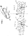
- Sole 10 may be permanently attached to shoe 11 or may be removable therefrom and placed, either with another, similar sole after excessive wear, or with another sole that has different characteristics.
- sole 10 has a bottom, work-contacting surface 12, from which protrude a plurality of metal studs 13.
- the upper surface 14 of the sole is not seen in FIG. 1, but lies in juxtaposition to the upper of the shoe 11.
- the pattern in which the studs 13 are arranged is predetermined and is not considered to be part of the present invention.
- each stud 13 is formed with an anchoring portion 15, a tip portio16, and a cylindrical or conical shank or shaft portion 17 so that it will remain substantially in place in relation to the resilient material of the sole in which it is encased.
- the tip 16 may be of a variety of shapes so long as its function of engaging a surface on which the wearer of the footwear 11 places it is maintained.
- the tip portion 16 is shown as cylindrical, but may also be conical with the apex of the cone projecting outwardly from the bottom surface 12 of the sole 10.
- the shaft 17 serves the function of connecting the tip and anchor of a stud. Indeed, the tip portion may simply be constituted as the extremity of the shaft 18.
- Portions of intermediate density lie between the zones 20 and 21, and are indicated by reference numeral 22.
- the density of the sole 10 decreases from the sole bottom surface 12 to the sole upper surface 14, and in this embodiment it is preferred that such decrease be uniform in its extent, that is, that the resilience of the sole uniformly increases as one moves from the bottom surface 12 to the upper surface 14 of the sole 10.
- the anchoring portion 16 of the stud 13 is embedded in the rubber sole approximately halfway between the bottom and top sole surfaces. In this position the anchor 15 is located at a part of the thickness of the sole that is of lesser density and greater resilience than that portion 20 adjoining bottom surface 12.
- the stud 13 will be able to be retracted more easily when the user of the footwear 22 steps on a hard surface than if the resilience of the sole were uniform throughout its depth. Yet the hardness of the rubber at the bottom surface of the sole will still be of greater density, and therefore provide greater wear resistance and sturdiness to the footwear. However, retraction of the stud will still be adequate if the wearer of the shoe is of light weight, for example.
- FIG. 3 shows a different, preferred embodiment.
- harder rubber layers are disposed adjoining both surfaces of the sole 10.
- a relatively hard layer 25 is located at the bottom surface 12 of the sole and, similarly, hard layer 26 is located at the upper surface 14 of the sole.
- those relatively hard layers have between them a softer, more resilient layer or zone 27, which in effect is sandwiched between the more dense layers.
- the reason for the layering of more and less resilient zones in the FIG. 3 embodiment is to enable the stud 13 to be retracted more easily into the sole 10, while still maintaining a relatively firm sole bottom surface that will resist undue wear.
- the shaft 17 of stud 13 extends through the less resilient portion 25 and into the more resilient portion 27, in which the anchor 15 of stud 13 is located.
- the stud is more readily retractable because its anchor portion 15 is encased within the more resilient zone 27.
- the less resilient outer layer 25 adjoining the bottom surface 12 of the sole 10 is in contact with the work, i.e., the surface on which the wearer is striding. In this manner ease of retractability of the stud or spike is enhanced while the wear resistance of the footwear is the same as if the denser bottom layer of the sole extended throughout the entirety of the sole.
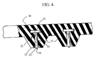
- FIG. 4 of the drawings Still another embodiment of my invention is illustrated in FIG. 4 of the drawings.
- the sole 30 is formed of a single zone of rubber, and a cleat portion 31 extends downwardly and forms, in part, the bottom surface of the sole.
- a stud 32 Encased within the body of the sole is a stud 32, comprised of an anchor 33 and a tip 34 joined by a shaft 35 that extends substantially perpendicular to the horizontal axis of the sole 30.
- the groove 37 that surrounds the tip and forms an annular opening about the tip 34 and in this case a lower portion of the shaft 35.
- the shaft of the stud 32 is usually formed from metal, providing such an annular recess 37 enables some flexing of the stud when it contacts a hard surface, and such flexing permits unwanted scarification of that surface in addition to the resilience imparted by the stud anchor 33 embedded in the resilient sole 30.
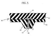
- FIG. 5 shows another preferring embodiment of my invention that is similar to that of FIG. 4.
- the sole 40 is formed from two layers of rubber, an upper or inner layer 41 and an outer, work contacting zone or layer 42.
- a stud 43 is provided, which stud includes an anchor 44 joined by a shaft 45 to a stud tip 46.
- the tip 46 is surrounded by annular recess 47 to permit some flexing of the tip and associated shank 45.
- outer layer or zone 42 is of harder, more wear resistance material, while inner layer 41 is more resilient. So, as the anchoring portion 44 of stud 43 is backed by more resilient zone 41, the stud can be retracted far more easily than if it had to press against the harder, less resilient zone 42.
- sole 50 is formed from a relatively hard upper layer 51 of rubber or other material, to which is adhered a relatively resilient layer 52. Then a cleat 53 formed of relatively hard rubber protrudes downwardly from the resilient layer 52. The stud 54 extends with its tip 55 in hard layer 53 and shaft 56 passing through that hard layer into zone 52 in which its anchor 57 is encompassed.
- the stud 54 can be retracted with a fair degree of ease, as its anchor need only compress a part of the more resilient layer 52 while both the work contacting cleat 53 and the upper layer 51 of the sole 50 are formed from a less resilient material adapted to provide great wear resistance and rigidity to the sole in its entirety.
- the annular recess 57 permits some flexibility of the tip and tip 55 and shaft 56 of the stud 54.
- the soles disclosed herein can be made by molding in one piece or, where the sole is formed from layers of materials of difference degrees of resilience, by separately forming each layer and then fusing the layers together.
- the hardness of the synthetic or natural rubber compounds utilized will vary as set forth in U.S. Patent No. 5,634,283 , from between about65 to 90 Durometer Shor A. Where greater hardness and less resilience are desired, the sole hardness will be at a maximum, whereas where much more resilience is desired, the Shor Durometer hardness will be at a minimum.
Abstract
Description
- The present invention relates to improvements in resilient, all-surface soles that are applied to or or are integral part of footwear. More specifically, it relates to improvements in such soles as described, illustrated and claimed in
U.S. Patent No. 5,634,283, which was issued on June 3, 1997 . - As more fully disclosed in
U.S. Patent No. 5,634,283 , it has long been a challenge to those of skill in the art of designing footwear to devise footwear having soles that enable the wearer to have traction on surfaces that may be classified as slippery, e.g., ice or wet sod. With regard to the latter surfaces, golf shoes are a common expedient. Golf shoes normally have soles with metal spikes or studs that extend at right angles to the bottom surface of the sole, so that when the golf shoes are worn on sod, the spikes readily penetrate the sod to a depth such that, when the golfer exerts downward pressure on the shoe sole, the footwear remains in a fixed position relative to the sod despite substantial torque that is applied by the golfer during his swing. - It will be apparent, however, that while shoes having soles with spikes extending outwardly from them are quite useful when one is walking on sod, or even a surface such as ice or compacted snow, when one then stands on a hard, smooth surface into which the spikes can make no substantial penetration, such spiked footwear can be a hazard to the wearer as well as the hard surface, which can be defaced and scratched by the shoe spikes.
- In order to address this problem my prior patent disclosed and claimed a footwear sole formed from a resilient material such as rubber and having a pluralityof metal studs mounted in the sole, each stud or spike having an anchoring poortion embedded in the resilient sole, a tip portion extending outwardly from the sole surface, and a shaft portion joining the tip and the anchor of the stud. When the footwear is worn, the studs are retracted inwardly from the surface of the sole so that on a hard surface, the tip portions of the studs will be located at the relatively hard surface and will not penetrate it. However, when the wearer is standing on a relatively soft surface, such as sod or wet ice, the studs will extend outwardly from the sole a distance sufficient to enable the wearer to obtain purchase on that softer surface due to penetration of the studs into the surface.
- While that invention is broadly utilitarian, it does not address problems that may arise in specific situations. Thus, where a woman's shoe is to be made with such a sole, it is apparent that pressure on the resilient sole will be less than that exerted by a shoe where the wearer is a 300-1b. man. Moreover, if the sole is formed from rubber or other material of a high degree of resilience such tht when the shoe is worn by a lightweight person the studs will nevertheless retract to the bottom surface of the sole, the sole formed from such soft rubber may not present a firm support to the wearer. In addition, even when there is an optimum balance between the resilience of the sole and the weight of the wearer, there still may be some scarification of a hard surface when the wearer of the shoes slides his or her feet across that surface.
-
EP-A-0 223 700 upon which the pre-characterising clause of claim 1 is based, attempts to solve this problem via the disclosure of a shoe comprising a sole formed form a resilient material that has a plurality of studs extending from a bottom surface thereof, the resilient material being non-uniform in its degree of resilience such that it is less resilient at said bottom surface than in a more resilient interior portion of said sole. Additionally, other soles are also discussed inEP 0518539 ,GB 2248762 EP 0207063 ,DE801897 ,US 31 70251 andUS 6 029 377 . - It is an object of my invention to more advantageously overcome the problem of adapting a studded, resilient sole to varying surface and weights of the wearer so that the studs will readily engage surfaces on which they are designed to penetrate, but nevertheless enable the wearer to utilise the shoes or other footwear on a hard surface, such as a tile floor, without unduly marring the surface.
- According to the present invention there is provided a resilient, all-surface sole for footwear, said sole being formed from a resilient material and comprising a bottom, work contacting surface, and upper surface and a plurality of studs extending therefrom, the plurality of studs each having an anchor portion, a tip portion extending slightly beyond the plane of the bottom surface, and a shaft connecting said anchor portion and said tip portion, the resilient material being non-uniform in its degree of resilience such that it is less resilient at an exterior portion at said bottom surface than in a more resilient interior portion of said sole, characterised in that the anchor portion of said studs are embedded in said more resilient portion of said sole such that, when a compressive force is applied to said bottom surface of said sole, the tip portions of said studs retract therein, therein, so that, in use, the areas of the sole material surrounding the studs engage the floor surface and carry the weight of the wearer within the requirement of additional wear-resistant members.
- A resilient, all-surface sole in accordance with the invention has the advantage that the more resilient portion of the sole that engages the anchoring portion of the stud can be adapted to the specific condition toward which the stud is designed.
- In a preferred embodiment the sole is formed so that the resilience thereof varies between the bottom and upper surfaces of the sole. Such variation can be uniform, that is, less resilient at the bottom, work-contacting surface of the sole and more resilient at the portion of the sole that contact the shoe upper. In an alternative embodiment the sole is formed from layers of rubber, a less resilient layer being located at the bottom of the sole.
- In yet another embodiment the more resilient zone can be located between the two, harder zones of rubber . It is in this softer zone of rubber that the anchoring portion of a stud is located; in this manner an easily retractable stud is formed although the work contacting surface of the sole is relatively hard, so that the sole may be worn on a hard, indoor surface without unduly scuffing it.
- Preferably, a groove is furthermore provided in the bottom, work contacting surface of the sole. Such groove is annular in shape and surrounds the tip of a stud that projects from the bottom surface. As the stud has a degree of resilience, itself, the groove permits the stud to flex to the side when excess pressure is directed against it, rather than have the additional pressure on the study force the stud into a hard underlying surface which it will then tend to scar.
- With respect to processes for the manufacture of soles that have varying degrees of resilience through their depths, the soles can be formed in a single molding operation in which the resilient material, such as natural or synthetic rubber, has its composition varied from one surface of the sheet from which the soles are formed to the other surface. Alternatively, the sole can be molded from individual sheets. For example, two sheets of less resilient and one sheet or more resilient can be formed and cut to size, and the more resilient layer sandwiched between the harder layers and molded to them. Production efficiencies may determine which methods of forming the desired structures prove more effective.
- In order that the invention may be well understood, there will now be described some embodiments thereof, given by way of example, reference being made to the accompanying drawings, in which:
- FIG. 1 is a perspective view generally showing the exterior of footwear having an all-surface sole according to my invention;
- FIG. 2 is an enlarged sectional view illustrating the sole construction according to one preferred embodiment of my invention;
- FIG. 3 is an enlarge sectional view illustrating another preferred embodiment of a sole construction according to my invention;
- FIG. 4 is an enlarged sectional view of a third, preferred embodiment;
- FIG. 5 is another section illustrating a variant of the embodiment of FIG. 4, and
- FIG. 6 is still another sectional view showing a variation that comprises a combination of previously illustrated preferred embodiments.
- Referring now to the drawings, and in particular to FIG. 1 thereof, what is shown in an all-surface sole 10 in place on footwear 11. Sole 10 may be permanently attached to shoe 11 or may be removable therefrom and placed, either with another, similar sole after excessive wear, or with another sole that has different characteristics.
- As generally shown, sole 10 has a bottom, work-contacting surface 12, from which protrude a plurality of metal studs 13. The
upper surface 14 of the sole is not seen in FIG. 1, but lies in juxtaposition to the upper of the shoe 11. The pattern in which the studs 13 are arranged is predetermined and is not considered to be part of the present invention. - The structure of a stud 13, which is preferably made of metal, is best seen in FIGS. 2 and 3. As is the case with the studs of my
U.S. Patent No. 5,634,283 , each stud 13 is formed with an anchoring portion 15, a tip portio16, and a cylindrical or conical shank or shaft portion 17 so that it will remain substantially in place in relation to the resilient material of the sole in which it is encased. Thetip 16 may be of a variety of shapes so long as its function of engaging a surface on which the wearer of the footwear 11 places it is maintained. Thus, thetip portion 16 is shown as cylindrical, but may also be conical with the apex of the cone projecting outwardly from the bottom surface 12 of the sole 10. The shaft 17 serves the function of connecting the tip and anchor of a stud. Indeed, the tip portion may simply be constituted as the extremity of the shaft 18. - What is important to certain embodiments of my resilient, all-surface sole is the nature of the composition of the sole 10. In
US Patent No. 5,634,283 it is disclosed, but not limited to being uniform and made from a resilient material, e.g., natural or synthetic rubber.In the embodiment of FIG. 2 of this application the material from which the sole is formed is of the same general, resilient nature, but the sole is not uniform in substance or resiliency. The rubber body of the sole is harder, that is, of less resilience, at a location adjoining the bottom, work contacting surface 12 of the sole 10. More dense, less resilient zones of the sole are indicated byreference number 20 and adjoin bottom surface 12. Less dense portions are indicated byreference number 21 and adjoin uppersole surface 14. Portions of intermediate density lie between thezones upper surface 14, and in this embodiment it is preferred that such decrease be uniform in its extent, that is, that the resilience of the sole uniformly increases as one moves from the bottom surface 12 to theupper surface 14 of the sole 10. - In the FIG. 2 embodiment it will also been seen that the
anchoring portion 16 of the stud 13 is embedded in the rubber sole approximately halfway between the bottom and top sole surfaces. In this position the anchor 15 is located at a part of the thickness of the sole that is of lesser density and greater resilience than thatportion 20 adjoining bottom surface 12. In this structure the stud 13 will be able to be retracted more easily when the user of the footwear 22 steps on a hard surface than if the resilience of the sole were uniform throughout its depth. Yet the hardness of the rubber at the bottom surface of the sole will still be of greater density, and therefore provide greater wear resistance and sturdiness to the footwear. However, retraction of the stud will still be adequate if the wearer of the shoe is of light weight, for example. - The illustration of FIG. 3 shows a different, preferred embodiment. Here harder rubber layers are disposed adjoining both surfaces of the sole 10. Thus, a relatively
hard layer 25 is located at the bottom surface 12 of the sole and, similarly, hard layer 26 is located at theupper surface 14 of the sole. However, those relatively hard layers have between them a softer, more resilient layer orzone 27, which in effect is sandwiched between the more dense layers. - The reason for the layering of more and less resilient zones in the FIG. 3 embodiment is to enable the stud 13 to be retracted more easily into the sole 10, while still maintaining a relatively firm sole bottom surface that will resist undue wear. Thus, in this embodiment of my invention the shaft 17 of stud 13 extends through the less
resilient portion 25 and into the moreresilient portion 27, in which the anchor 15 of stud 13 is located. In this manner the stud is more readily retractable because its anchor portion 15 is encased within the moreresilient zone 27. Still, the less resilientouter layer 25 adjoining the bottom surface 12 of the sole 10 is in contact with the work, i.e., the surface on which the wearer is striding. In this manner ease of retractability of the stud or spike is enhanced while the wear resistance of the footwear is the same as if the denser bottom layer of the sole extended throughout the entirety of the sole. - Still another embodiment of my invention is illustrated in FIG. 4 of the drawings. Here the sole 30 is formed of a single zone of rubber, and a
cleat portion 31 extends downwardly and forms, in part, the bottom surface of the sole. Encased within the body of the sole is astud 32, comprised of ananchor 33 and atip 34 joined by ashaft 35 that extends substantially perpendicular to the horizontal axis of the sole 30. What is believed to be unique vis-α-vis my prior patent, however, is thegroove 37 that surrounds the tip and forms an annular opening about thetip 34 and in this case a lower portion of theshaft 35. As the shaft of thestud 32 is usually formed from metal, providing such anannular recess 37 enables some flexing of the stud when it contacts a hard surface, and such flexing permits unwanted scarification of that surface in addition to the resilience imparted by thestud anchor 33 embedded in the resilient sole 30. - FIG. 5 shows another preferring embodiment of my invention that is similar to that of FIG. 4. The difference here is that the sole 40 is formed from two layers of rubber, an upper or
inner layer 41 and an outer, work contacting zone orlayer 42. Astud 43 is provided, which stud includes ananchor 44 joined by ashaft 45 to astud tip 46. Here, too, thetip 46 is surrounded byannular recess 47 to permit some flexing of the tip and associatedshank 45. In the FIG. 5 embodiment outer layer orzone 42 is of harder, more wear resistance material, whileinner layer 41 is more resilient. So, as the anchoringportion 44 ofstud 43 is backed by moreresilient zone 41, the stud can be retracted far more easily than if it had to press against the harder, lessresilient zone 42. - Finally, the embodiment illustrated in FIG. 6 employs another combination of hard or more resilient layers of rubber. In this embodiment sole 50 is formed from a relatively hard
upper layer 51 of rubber or other material, to which is adhered a relativelyresilient layer 52. Then acleat 53 formed of relatively hard rubber protrudes downwardly from theresilient layer 52. Thestud 54 extends with itstip 55 inhard layer 53 andshaft 56 passing through that hard layer intozone 52 in which itsanchor 57 is encompassed. In this structure thestud 54 can be retracted with a fair degree of ease, as its anchor need only compress a part of the moreresilient layer 52 while both thework contacting cleat 53 and theupper layer 51 of the sole 50 are formed from a less resilient material adapted to provide great wear resistance and rigidity to the sole in its entirety. In this embodiment as well, theannular recess 57 permits some flexibility of the tip andtip 55 andshaft 56 of thestud 54. - With regard to the manufacture of the soles disclosed herein, they can be made by molding in one piece or, where the sole is formed from layers of materials of difference degrees of resilience, by separately forming each layer and then fusing the layers together. The hardness of the synthetic or natural rubber compounds utilized will vary as set forth in
U.S. Patent No. 5,634,283 , from between about65 to 90 Durometer Shor A. Where greater hardness and less resilience are desired, the sole hardness will be at a maximum, whereas where much more resilience is desired, the Shor Durometer hardness will be at a minimum. Nevertheless, such variation in hardness are doubtless within the skill of those in this art, and I do not wish to be limited as to any specific hardness or resilience employed, other than as such hardness or resilience in one part of the sole may be contrasted with those factors in another layer of the sole.
Claims (7)
- A resilient, all-surface sole (10) for footwear (11), said sole (10) being formed from a resilient material and comprising a bottom, work contacting surface (12), an upper surface (14) and a plurality of studs (13) extending therefrom, the plurality of studs (13) each having an anchor portion (15), a tip portion (16) extending slightly beyond the plane of the bottom surface (12), and a shaft (17) connecting said anchor portion (15) and said tip portion (16), the resilient material being non-uniform in its degree of resilience such that it is less resilient at an exterior portion at said bottom surface (12) than in a more resilient interior portion of said sole (10), characterised in that the anchor portion (15) of said studs (13) are embedded in said more resilient portion of said sole (10) such that, when a compressive force is applied to said bottom surface (12) of said sole (10), the tip portions (16) of said studs (13) retract therein, so that, in use, the areas of the sole material surrounding the studs engage the floor surface and carry the weight of the wearer without the need for additional wear-resistant members.
- A sole as claimed in claim 1, wherein said resilient material is in the form of layers, a less resilient layer being located at a lower portion of the sole (10) and terminating in the bottom, work contacting surface (12) of said sole (10) and a more resilient layer being located at an upper portion of said sole (10) adjacent said less resilient layer.
- A sole as claimed in claim 1, wherein said resilient material is in the form of layers (25,26,27) a first less resilient layer (25) being located at a lower portion of the sole (10) and terminating in said bottom, work contacting surface (12) of said sole (10), a more resilient layer (27) being located contignously with said less resilient layer (25) and extending upwardly therefrom, and a second, less resilient layer (26) being located contignously with said more resilient layer (27), said first and second less resilient layers (25,26) being adhered to and sandwiching said more resilient layer (27) between them.
- A sole as claimed in claim 2 or claim 3, wherein said stud anchor (15) is embedded in said more resilient layer.
- A sole as claimed in claim 2 or claim 3, wherein said stud anchor (15) is positioned at the lower border of the more resilient layer.
- A sole according to any of the previous claims, wherein the bottom surface of the sole (30,40,50) is formed with a recess (37,47,57) at a location where the tip portion (34,46,55) of the stud (32,43,54) extends outwardly from the plane of said bottom surface and said tip portion (34,46,55) flexes in said recesses (37,47,57) formed at said location.
- A sole according to any of the preceding claims, wherein the sole (50) includes a plurality of cleats (53) on its lower surface, each cleat having a lower surface which, together, form the bottom, work contact surface of the sole (50), each stud (56) being mounted in one of said cleats (53) within its tip retractably extending beyond the lower surface of the clear (53).
Applications Claiming Priority (2)
| Application Number | Priority Date | Filing Date | Title |
|---|---|---|---|
| US948597 | 1978-10-04 | ||
| US09/948,597 US20020029495A1 (en) | 2000-09-08 | 2001-09-10 | Resilient, all-surface soles for footwear |
Publications (3)
| Publication Number | Publication Date |
|---|---|
| EP1290958A2 EP1290958A2 (en) | 2003-03-12 |
| EP1290958A3 EP1290958A3 (en) | 2003-10-22 |
| EP1290958B1 true EP1290958B1 (en) | 2007-10-31 |
Family
ID=25488031
Family Applications (1)
| Application Number | Title | Priority Date | Filing Date |
|---|---|---|---|
| EP02256110A Expired - Lifetime EP1290958B1 (en) | 2001-09-10 | 2002-09-03 | Resilient all-surface soles for footwear |
Country Status (7)
| Country | Link |
|---|---|
| US (2) | US20020029495A1 (en) |
| EP (1) | EP1290958B1 (en) |
| JP (1) | JP4112321B2 (en) |
| CN (1) | CN1253117C (en) |
| AT (1) | ATE376781T1 (en) |
| DE (1) | DE60223210T2 (en) |
| RU (1) | RU2298392C2 (en) |
Families Citing this family (46)
| Publication number | Priority date | Publication date | Assignee | Title |
|---|---|---|---|---|
| WO2003030670A1 (en) * | 2001-10-10 | 2003-04-17 | Cole Charles D Iii | Apparatus and methods for imbedded rubber outer |
| US7234250B2 (en) * | 2005-02-07 | 2007-06-26 | Stacy Renee Fogarty | Convertible traction shoes |
| US20080066348A1 (en) * | 2005-02-07 | 2008-03-20 | Select Sole, Llc | Footwear with retractable members |
| US20070113424A1 (en) * | 2005-11-23 | 2007-05-24 | Michael Bell | Overshoes with raised inner surface portions and slip resistant sole portions for use on primary footwear |
| US9795181B2 (en) * | 2007-10-23 | 2017-10-24 | Nike, Inc. | Articles and methods of manufacture of articles |
| US9572402B2 (en) | 2007-10-23 | 2017-02-21 | Nike, Inc. | Articles and methods of manufacturing articles |
| US9788603B2 (en) * | 2007-10-23 | 2017-10-17 | Nike, Inc. | Articles and methods of manufacture of articles |
| US8256145B2 (en) * | 2008-09-26 | 2012-09-04 | Nike, Inc. | Articles with retractable traction elements |
| US8079160B2 (en) * | 2008-09-26 | 2011-12-20 | Nike, Inc. | Articles with retractable traction elements |
| CN102421316B (en) | 2009-04-02 | 2015-11-25 | 耐克创新有限合伙公司 | traction elements |
| US8616892B2 (en) | 2009-04-02 | 2013-12-31 | Nike, Inc. | Training system for an article of footwear with a traction system |
| US20100269374A1 (en) * | 2009-04-22 | 2010-10-28 | Chin-Long Hsieh | Sole structure and method of making the same |
| US8632342B2 (en) | 2009-05-28 | 2014-01-21 | Nike, Inc. | Training system for an article of footwear |
| US8573981B2 (en) | 2009-05-29 | 2013-11-05 | Nike, Inc. | Training system for an article of footwear with a ball control portion |
| US8578631B2 (en) * | 2009-08-25 | 2013-11-12 | Gene A. Francello | Extendable spikes for shoes |
| US8453354B2 (en) * | 2009-10-01 | 2013-06-04 | Nike, Inc. | Rigid cantilevered stud |
| DE202009016139U1 (en) * | 2009-11-30 | 2010-03-18 | X-Technology Swiss Gmbh | sole |
| US8745897B2 (en) * | 2009-12-08 | 2014-06-10 | Lacrosse Footwear, Inc. | Traction enhancing devices for footwear assemblies |
| US8533979B2 (en) * | 2010-02-18 | 2013-09-17 | Nike, Inc. | Self-adjusting studs |
| US8322051B2 (en) | 2010-02-23 | 2012-12-04 | Nike, Inc. | Self-adjusting studs |
| US9210967B2 (en) | 2010-08-13 | 2015-12-15 | Nike, Inc. | Sole structure with traction elements |
| US8529267B2 (en) | 2010-11-01 | 2013-09-10 | Nike, Inc. | Integrated training system for articles of footwear |
| US8695234B2 (en) * | 2010-12-27 | 2014-04-15 | Han-Ching Wu | Anti-slip spike structure |
| GB2486895B (en) * | 2010-12-27 | 2013-09-18 | Han-Ching Wu | Improved anti-slip spike structure |
| US8713819B2 (en) | 2011-01-19 | 2014-05-06 | Nike, Inc. | Composite sole structure |
| US9504293B2 (en) | 2011-04-18 | 2016-11-29 | Nike, Inc. | Outsole with extendable traction elements |
| US9138027B2 (en) | 2011-09-16 | 2015-09-22 | Nike, Inc. | Spacing for footwear ground-engaging member support features |
| US9220320B2 (en) | 2011-09-16 | 2015-12-29 | Nike, Inc. | Sole arrangement with ground-engaging member support features |
| US8966787B2 (en) | 2011-09-16 | 2015-03-03 | Nike, Inc. | Orientations for footwear ground-engaging member support features |
| US8806779B2 (en) | 2011-09-16 | 2014-08-19 | Nike, Inc. | Shaped support features for footwear ground-engaging members |
| US9402442B2 (en) | 2012-04-27 | 2016-08-02 | Nike, Inc. | Sole structure and article of footwear including same |
| RU2492781C1 (en) * | 2012-05-11 | 2013-09-20 | Павел Андреевич Белов | Anti-icing overshoes |
| US9032645B2 (en) | 2012-07-30 | 2015-05-19 | Nike, Inc. | Support features for footwear ground engaging members |
| US9320316B2 (en) | 2013-03-14 | 2016-04-26 | Under Armour, Inc. | 3D zonal compression shoe |
| US10524543B2 (en) * | 2013-11-15 | 2020-01-07 | Nike, Inc. | Article of footwear with self-cleaning cleats |
| EP2893827B1 (en) * | 2013-12-17 | 2020-05-27 | Kahtoola, Inc. | Footwear traction devices and systems and mechanisms for making durable connections to soft body materials |
| DE202014102743U1 (en) | 2014-06-13 | 2014-06-24 | Han-Ching Wu | Anti-slip safety device |
| US9622545B2 (en) * | 2015-01-26 | 2017-04-18 | Joneric Products, Inc. | Dual-molded layer overshoe |
| US10010133B2 (en) | 2015-05-08 | 2018-07-03 | Under Armour, Inc. | Midsole lattice with hollow tubes for footwear |
| US10010134B2 (en) | 2015-05-08 | 2018-07-03 | Under Armour, Inc. | Footwear with lattice midsole and compression insert |
| US20180070680A1 (en) * | 2016-09-15 | 2018-03-15 | Tingley Rubber Corporation | Traction Studs And Outsoles |
| CN110475491A (en) * | 2016-12-27 | 2019-11-19 | 夹持力技术公司 | On-slip shoes |
| US11089839B1 (en) | 2018-01-15 | 2021-08-17 | Anthony Louis Chechile | Sport shoe of the self-cleaning variety with a compressible cleaning structure |
| IT201800021307A1 (en) * | 2018-12-28 | 2020-06-28 | Progress Plast S N C Di Bordin Lino & C | PERFECTED NON-SLIP NAIL SOLE |
| EP3827691A1 (en) | 2019-12-01 | 2021-06-02 | Kahtoola, Inc. | Footwear traction device and method of using the same |
| RU2743113C1 (en) * | 2020-02-11 | 2021-02-15 | Георгий Яковлевич Пустовой | Shoe sole with anti-slip holes |
Family Cites Families (17)
| Publication number | Priority date | Publication date | Assignee | Title |
|---|---|---|---|---|
| US19205A (en) * | 1858-01-26 | Heel-spttb to prevent slipping on ice | ||
| US2258734A (en) * | 1939-06-22 | 1941-10-14 | David R Brady | Peg for athletic shoes |
| US2424226A (en) * | 1940-11-01 | 1947-07-22 | Dufour Eric | Nonslipping rubber sole |
| DE801897C (en) * | 1949-01-18 | 1951-01-25 | Adolf Dassler Fa | Racing shoe with thorns |
| US3170251A (en) * | 1963-05-03 | 1965-02-23 | Patrick Raymond | Antiskid attachment for shoes |
| US3747238A (en) * | 1972-04-10 | 1973-07-24 | J Jankauskas | Studded footwear |
| JPS5637362Y2 (en) * | 1978-08-16 | 1981-09-02 | ||
| US4466205A (en) * | 1983-01-10 | 1984-08-21 | Corbari George V | Safety stud |
| AT388488B (en) * | 1985-06-18 | 1989-06-26 | Hartjes Rudolf | GOLF SHOE |
| US4747220A (en) * | 1987-01-20 | 1988-05-31 | Autry Industries, Inc. | Cleated sole for activewear shoe |
| JPH0462107U (en) * | 1990-10-11 | 1992-05-28 | ||
| NZ242909A (en) * | 1991-06-04 | 1994-12-22 | Ishikawa Giken Gomu Kk | Rubber spike pin projects within tread open mounting recess |
| US5634283A (en) | 1995-05-03 | 1997-06-03 | Kastner; Sidney | Resilient, all-surface sole |
| IT1275516B (en) * | 1995-07-12 | 1997-08-07 | Vibram Spa | SPORTY SOLE WITH INCREASED STABILITY IN ONE PIECE |
| IT1287224B1 (en) * | 1996-03-29 | 1998-08-04 | D B A S R L | SOLE FOR FOOTWEAR |
| US6029377A (en) * | 1997-06-19 | 2000-02-29 | Bridgestone Sports, Co., Ltd. | Athletic shoe |
| US6698110B1 (en) * | 2002-10-28 | 2004-03-02 | Timothy A. Robbins | Spiked shoe having a spike cleaning cushion |
-
2001
- 2001-09-10 US US09/948,597 patent/US20020029495A1/en not_active Abandoned
-
2002
- 2002-09-03 EP EP02256110A patent/EP1290958B1/en not_active Expired - Lifetime
- 2002-09-03 DE DE60223210T patent/DE60223210T2/en not_active Expired - Lifetime
- 2002-09-03 AT AT02256110T patent/ATE376781T1/en active
- 2002-09-09 RU RU2002123916/12A patent/RU2298392C2/en not_active IP Right Cessation
- 2002-09-10 JP JP2002264575A patent/JP4112321B2/en not_active Expired - Fee Related
- 2002-09-10 CN CNB021416842A patent/CN1253117C/en not_active Expired - Fee Related
-
2004
- 2004-03-22 US US10/613,575 patent/US6915595B2/en not_active Expired - Fee Related
Also Published As
| Publication number | Publication date |
|---|---|
| DE60223210D1 (en) | 2007-12-13 |
| ATE376781T1 (en) | 2007-11-15 |
| EP1290958A3 (en) | 2003-10-22 |
| DE60223210T2 (en) | 2008-02-28 |
| JP4112321B2 (en) | 2008-07-02 |
| US20020029495A1 (en) | 2002-03-14 |
| CN1408295A (en) | 2003-04-09 |
| JP2003093103A (en) | 2003-04-02 |
| CN1253117C (en) | 2006-04-26 |
| EP1290958A2 (en) | 2003-03-12 |
| RU2298392C2 (en) | 2007-05-10 |
| US20040134102A1 (en) | 2004-07-15 |
| US6915595B2 (en) | 2005-07-12 |
| RU2002123916A (en) | 2004-03-27 |
Similar Documents
| Publication | Publication Date | Title |
|---|---|---|
| EP1290958B1 (en) | Resilient all-surface soles for footwear | |
| US5634283A (en) | Resilient, all-surface sole | |
| EP3260006B1 (en) | Self-adjusting studs | |
| US10932527B2 (en) | Cleated footwear with flexible cleats | |
| AU717551B2 (en) | Footwear cleat | |
| US4607440A (en) | Outsole for athletic shoe | |
| CN106170219B (en) | Sole for footwear, and systems and methods for designing and manufacturing same | |
| US6817117B1 (en) | Golf shoe outsole with oriented traction elements | |
| US7866064B2 (en) | Interchangeable pod system | |
| US5979083A (en) | Multi-layer outsole | |
| EP2879539B1 (en) | Footwear article comprising an outsole having fin traction elements | |
| US20160295959A1 (en) | Article of Footwear With Sole Structure Having Frusto-Conical Structures | |
| CA2261881A1 (en) | Footwear apparatus with grinding plate and method of making same | |
| JPS6329522B2 (en) | ||
| US6662475B2 (en) | Reversible heel | |
| US6138386A (en) | Composite cleat for athletic shoe | |
| US4920663A (en) | Athletic shoe, particularly a tennis shoe, and process for producing such a shoe | |
| WO2003045182A1 (en) | Grip for footwear | |
| EP0980655A2 (en) | Improved high heel footwear structure | |
| JPH119302A (en) | Sports shoes | |
| JP6881759B2 (en) | Sole, shoes and non-slip members | |
| US20240138512A1 (en) | Golf shoes having multi-surface traction outsoles | |
| US20220175080A1 (en) | Golf shoes having multi-surface traction outsoles | |
| CA2193437C (en) | Resilient, all-surface sole | |
| JPH0127683Y2 (en) |
Legal Events
| Date | Code | Title | Description |
|---|---|---|---|
| PUAI | Public reference made under article 153(3) epc to a published international application that has entered the european phase |
Free format text: ORIGINAL CODE: 0009012 |
|
| AK | Designated contracting states |
Kind code of ref document: A2 Designated state(s): AT BE BG CH CY CZ DE DK EE ES FI FR GB GR IE IT LI LU MC NL PT SE SK TR |
|
| AX | Request for extension of the european patent |
Extension state: AL LT LV MK RO SI |
|
| PUAL | Search report despatched |
Free format text: ORIGINAL CODE: 0009013 |
|
| RIC1 | Information provided on ipc code assigned before grant |
Ipc: 7A 43B 13/12 B Ipc: 7A 43C 15/16 B Ipc: 7A 43B 13/00 A Ipc: 7A 43B 13/26 B |
|
| AK | Designated contracting states |
Kind code of ref document: A3 Designated state(s): AT BE BG CH CY CZ DE DK EE ES FI FR GB GR IE IT LI LU MC NL PT SE SK TR |
|
| AX | Request for extension of the european patent |
Extension state: AL LT LV MK RO SI |
|
| 17P | Request for examination filed |
Effective date: 20040323 |
|
| AKX | Designation fees paid |
Designated state(s): AT BE BG CH CY CZ DE DK EE ES FI FR GB GR IE IT LI LU MC NL PT SE SK TR |
|
| 17Q | First examination report despatched |
Effective date: 20050330 |
|
| 17Q | First examination report despatched |
Effective date: 20050330 |
|
| GRAP | Despatch of communication of intention to grant a patent |
Free format text: ORIGINAL CODE: EPIDOSNIGR1 |
|
| GRAS | Grant fee paid |
Free format text: ORIGINAL CODE: EPIDOSNIGR3 |
|
| GRAA | (expected) grant |
Free format text: ORIGINAL CODE: 0009210 |
|
| AK | Designated contracting states |
Kind code of ref document: B1 Designated state(s): AT BE BG CH CY CZ DE DK EE ES FI FR GB GR IE IT LI LU MC NL PT SE SK TR |
|
| REG | Reference to a national code |
Ref country code: GB Ref legal event code: FG4D |
|
| REG | Reference to a national code |
Ref country code: SE Ref legal event code: TRGR |
|
| REG | Reference to a national code |
Ref country code: IE Ref legal event code: FG4D |
|
| REG | Reference to a national code |
Ref country code: CH Ref legal event code: EP Ref country code: CH Ref legal event code: NV Representative=s name: ISLER & PEDRAZZINI AG |
|
| REF | Corresponds to: |
Ref document number: 60223210 Country of ref document: DE Date of ref document: 20071213 Kind code of ref document: P |
|
| NLV1 | Nl: lapsed or annulled due to failure to fulfill the requirements of art. 29p and 29m of the patents act | ||
| PG25 | Lapsed in a contracting state [announced via postgrant information from national office to epo] |
Ref country code: NL Free format text: LAPSE BECAUSE OF FAILURE TO SUBMIT A TRANSLATION OF THE DESCRIPTION OR TO PAY THE FEE WITHIN THE PRESCRIBED TIME-LIMIT Effective date: 20071031 Ref country code: ES Free format text: LAPSE BECAUSE OF FAILURE TO SUBMIT A TRANSLATION OF THE DESCRIPTION OR TO PAY THE FEE WITHIN THE PRESCRIBED TIME-LIMIT Effective date: 20080211 |
|
| PG25 | Lapsed in a contracting state [announced via postgrant information from national office to epo] |
Ref country code: PT Free format text: LAPSE BECAUSE OF FAILURE TO SUBMIT A TRANSLATION OF THE DESCRIPTION OR TO PAY THE FEE WITHIN THE PRESCRIBED TIME-LIMIT Effective date: 20080331 Ref country code: BG Free format text: LAPSE BECAUSE OF FAILURE TO SUBMIT A TRANSLATION OF THE DESCRIPTION OR TO PAY THE FEE WITHIN THE PRESCRIBED TIME-LIMIT Effective date: 20080131 |
|
| ET | Fr: translation filed | ||
| PG25 | Lapsed in a contracting state [announced via postgrant information from national office to epo] |
Ref country code: DK Free format text: LAPSE BECAUSE OF FAILURE TO SUBMIT A TRANSLATION OF THE DESCRIPTION OR TO PAY THE FEE WITHIN THE PRESCRIBED TIME-LIMIT Effective date: 20071031 Ref country code: CZ Free format text: LAPSE BECAUSE OF FAILURE TO SUBMIT A TRANSLATION OF THE DESCRIPTION OR TO PAY THE FEE WITHIN THE PRESCRIBED TIME-LIMIT Effective date: 20071031 |
|
| PG25 | Lapsed in a contracting state [announced via postgrant information from national office to epo] |
Ref country code: BE Free format text: LAPSE BECAUSE OF FAILURE TO SUBMIT A TRANSLATION OF THE DESCRIPTION OR TO PAY THE FEE WITHIN THE PRESCRIBED TIME-LIMIT Effective date: 20071031 Ref country code: SK Free format text: LAPSE BECAUSE OF FAILURE TO SUBMIT A TRANSLATION OF THE DESCRIPTION OR TO PAY THE FEE WITHIN THE PRESCRIBED TIME-LIMIT Effective date: 20071031 |
|
| PLBE | No opposition filed within time limit |
Free format text: ORIGINAL CODE: 0009261 |
|
| STAA | Information on the status of an ep patent application or granted ep patent |
Free format text: STATUS: NO OPPOSITION FILED WITHIN TIME LIMIT |
|
| 26N | No opposition filed |
Effective date: 20080801 |
|
| PG25 | Lapsed in a contracting state [announced via postgrant information from national office to epo] |
Ref country code: GR Free format text: LAPSE BECAUSE OF FAILURE TO SUBMIT A TRANSLATION OF THE DESCRIPTION OR TO PAY THE FEE WITHIN THE PRESCRIBED TIME-LIMIT Effective date: 20080201 |
|
| PG25 | Lapsed in a contracting state [announced via postgrant information from national office to epo] |
Ref country code: FI Free format text: LAPSE BECAUSE OF FAILURE TO SUBMIT A TRANSLATION OF THE DESCRIPTION OR TO PAY THE FEE WITHIN THE PRESCRIBED TIME-LIMIT Effective date: 20071031 |
|
| PG25 | Lapsed in a contracting state [announced via postgrant information from national office to epo] |
Ref country code: MC Free format text: LAPSE BECAUSE OF NON-PAYMENT OF DUE FEES Effective date: 20080930 Ref country code: EE Free format text: LAPSE BECAUSE OF FAILURE TO SUBMIT A TRANSLATION OF THE DESCRIPTION OR TO PAY THE FEE WITHIN THE PRESCRIBED TIME-LIMIT Effective date: 20071031 |
|
| PG25 | Lapsed in a contracting state [announced via postgrant information from national office to epo] |
Ref country code: CY Free format text: LAPSE BECAUSE OF FAILURE TO SUBMIT A TRANSLATION OF THE DESCRIPTION OR TO PAY THE FEE WITHIN THE PRESCRIBED TIME-LIMIT Effective date: 20071031 Ref country code: IE Free format text: LAPSE BECAUSE OF NON-PAYMENT OF DUE FEES Effective date: 20080903 |
|
| PG25 | Lapsed in a contracting state [announced via postgrant information from national office to epo] |
Ref country code: LU Free format text: LAPSE BECAUSE OF NON-PAYMENT OF DUE FEES Effective date: 20080903 |
|
| PG25 | Lapsed in a contracting state [announced via postgrant information from national office to epo] |
Ref country code: TR Free format text: LAPSE BECAUSE OF FAILURE TO SUBMIT A TRANSLATION OF THE DESCRIPTION OR TO PAY THE FEE WITHIN THE PRESCRIBED TIME-LIMIT Effective date: 20071031 |
|
| PGFP | Annual fee paid to national office [announced via postgrant information from national office to epo] |
Ref country code: AT Payment date: 20100910 Year of fee payment: 9 |
|
| PG25 | Lapsed in a contracting state [announced via postgrant information from national office to epo] |
Ref country code: IT Free format text: LAPSE BECAUSE OF NON-PAYMENT OF DUE FEES Effective date: 20080930 |
|
| REG | Reference to a national code |
Ref country code: AT Ref legal event code: MM01 Ref document number: 376781 Country of ref document: AT Kind code of ref document: T Effective date: 20110903 |
|
| PG25 | Lapsed in a contracting state [announced via postgrant information from national office to epo] |
Ref country code: AT Free format text: LAPSE BECAUSE OF NON-PAYMENT OF DUE FEES Effective date: 20110903 |
|
| PGFP | Annual fee paid to national office [announced via postgrant information from national office to epo] |
Ref country code: CH Payment date: 20140915 Year of fee payment: 13 Ref country code: DE Payment date: 20140903 Year of fee payment: 13 |
|
| PGFP | Annual fee paid to national office [announced via postgrant information from national office to epo] |
Ref country code: SE Payment date: 20140911 Year of fee payment: 13 Ref country code: GB Payment date: 20140903 Year of fee payment: 13 |
|
| PGFP | Annual fee paid to national office [announced via postgrant information from national office to epo] |
Ref country code: FR Payment date: 20140906 Year of fee payment: 13 |
|
| REG | Reference to a national code |
Ref country code: DE Ref legal event code: R119 Ref document number: 60223210 Country of ref document: DE |
|
| REG | Reference to a national code |
Ref country code: CH Ref legal event code: PL |
|
| REG | Reference to a national code |
Ref country code: SE Ref legal event code: EUG |
|
| GBPC | Gb: european patent ceased through non-payment of renewal fee |
Effective date: 20150903 |
|
| PG25 | Lapsed in a contracting state [announced via postgrant information from national office to epo] |
Ref country code: SE Free format text: LAPSE BECAUSE OF NON-PAYMENT OF DUE FEES Effective date: 20150904 |
|
| REG | Reference to a national code |
Ref country code: FR Ref legal event code: ST Effective date: 20160531 |
|
| PG25 | Lapsed in a contracting state [announced via postgrant information from national office to epo] |
Ref country code: GB Free format text: LAPSE BECAUSE OF NON-PAYMENT OF DUE FEES Effective date: 20150903 Ref country code: CH Free format text: LAPSE BECAUSE OF NON-PAYMENT OF DUE FEES Effective date: 20150930 Ref country code: DE Free format text: LAPSE BECAUSE OF NON-PAYMENT OF DUE FEES Effective date: 20160401 Ref country code: LI Free format text: LAPSE BECAUSE OF NON-PAYMENT OF DUE FEES Effective date: 20150930 |
|
| PG25 | Lapsed in a contracting state [announced via postgrant information from national office to epo] |
Ref country code: FR Free format text: LAPSE BECAUSE OF NON-PAYMENT OF DUE FEES Effective date: 20150930 |