EP1290792B1 - Verfahren und vorrichtung zur entzerrung von linear verzerrten signalen - Google Patents
Verfahren und vorrichtung zur entzerrung von linear verzerrten signalen Download PDFInfo
- Publication number
- EP1290792B1 EP1290792B1 EP00935187A EP00935187A EP1290792B1 EP 1290792 B1 EP1290792 B1 EP 1290792B1 EP 00935187 A EP00935187 A EP 00935187A EP 00935187 A EP00935187 A EP 00935187A EP 1290792 B1 EP1290792 B1 EP 1290792B1
- Authority
- EP
- European Patent Office
- Prior art keywords
- filter
- signal
- accordance
- output signal
- accumulator
- Prior art date
- Legal status (The legal status is an assumption and is not a legal conclusion. Google has not performed a legal analysis and makes no representation as to the accuracy of the status listed.)
- Expired - Lifetime
Links
- 238000000034 method Methods 0.000 title claims description 10
- 230000006978 adaptation Effects 0.000 claims description 11
- 238000012545 processing Methods 0.000 claims description 5
- 230000003044 adaptive effect Effects 0.000 claims description 4
- 230000004913 activation Effects 0.000 claims 1
- 238000001914 filtration Methods 0.000 claims 1
- 238000005562 fading Methods 0.000 description 4
- 230000005540 biological transmission Effects 0.000 description 3
- 230000000694 effects Effects 0.000 description 3
- 238000006243 chemical reaction Methods 0.000 description 2
- 238000005259 measurement Methods 0.000 description 2
- 238000012935 Averaging Methods 0.000 description 1
- 230000002238 attenuated effect Effects 0.000 description 1
- 230000015556 catabolic process Effects 0.000 description 1
- 238000006731 degradation reaction Methods 0.000 description 1
- 238000009795 derivation Methods 0.000 description 1
- 238000001514 detection method Methods 0.000 description 1
- 238000011161 development Methods 0.000 description 1
- 230000018109 developmental process Effects 0.000 description 1
- 238000010586 diagram Methods 0.000 description 1
- 238000010606 normalization Methods 0.000 description 1
- 238000011045 prefiltration Methods 0.000 description 1
- 230000000644 propagated effect Effects 0.000 description 1
- 230000008054 signal transmission Effects 0.000 description 1
Images


Classifications
-
- H—ELECTRICITY
- H04—ELECTRIC COMMUNICATION TECHNIQUE
- H04L—TRANSMISSION OF DIGITAL INFORMATION, e.g. TELEGRAPHIC COMMUNICATION
- H04L25/00—Baseband systems
- H04L25/02—Details ; arrangements for supplying electrical power along data transmission lines
- H04L25/03—Shaping networks in transmitter or receiver, e.g. adaptive shaping networks
- H04L25/03006—Arrangements for removing intersymbol interference
- H04L25/03012—Arrangements for removing intersymbol interference operating in the time domain
- H04L25/03019—Arrangements for removing intersymbol interference operating in the time domain adaptive, i.e. capable of adjustment during data reception
- H04L25/03038—Arrangements for removing intersymbol interference operating in the time domain adaptive, i.e. capable of adjustment during data reception with a non-recursive structure
- H04L25/03044—Arrangements for removing intersymbol interference operating in the time domain adaptive, i.e. capable of adjustment during data reception with a non-recursive structure using fractionally spaced delay lines or combinations of fractionally integrally spaced taps
-
- H—ELECTRICITY
- H03—ELECTRONIC CIRCUITRY
- H03H—IMPEDANCE NETWORKS, e.g. RESONANT CIRCUITS; RESONATORS
- H03H21/00—Adaptive networks
- H03H21/0012—Digital adaptive filters
-
- H—ELECTRICITY
- H04—ELECTRIC COMMUNICATION TECHNIQUE
- H04L—TRANSMISSION OF DIGITAL INFORMATION, e.g. TELEGRAPHIC COMMUNICATION
- H04L25/00—Baseband systems
- H04L25/02—Details ; arrangements for supplying electrical power along data transmission lines
- H04L25/03—Shaping networks in transmitter or receiver, e.g. adaptive shaping networks
- H04L25/03006—Arrangements for removing intersymbol interference
- H04L25/03012—Arrangements for removing intersymbol interference operating in the time domain
- H04L25/03019—Arrangements for removing intersymbol interference operating in the time domain adaptive, i.e. capable of adjustment during data reception
- H04L25/03038—Arrangements for removing intersymbol interference operating in the time domain adaptive, i.e. capable of adjustment during data reception with a non-recursive structure
- H04L25/0305—Arrangements for removing intersymbol interference operating in the time domain adaptive, i.e. capable of adjustment during data reception with a non-recursive structure using blind adaptation
-
- H—ELECTRICITY
- H04—ELECTRIC COMMUNICATION TECHNIQUE
- H04L—TRANSMISSION OF DIGITAL INFORMATION, e.g. TELEGRAPHIC COMMUNICATION
- H04L25/00—Baseband systems
- H04L25/02—Details ; arrangements for supplying electrical power along data transmission lines
- H04L25/03—Shaping networks in transmitter or receiver, e.g. adaptive shaping networks
- H04L25/03006—Arrangements for removing intersymbol interference
- H04L2025/0335—Arrangements for removing intersymbol interference characterised by the type of transmission
- H04L2025/03375—Passband transmission
- H04L2025/03401—PSK
- H04L2025/03407—Continuous phase
-
- H—ELECTRICITY
- H04—ELECTRIC COMMUNICATION TECHNIQUE
- H04L—TRANSMISSION OF DIGITAL INFORMATION, e.g. TELEGRAPHIC COMMUNICATION
- H04L25/00—Baseband systems
- H04L25/02—Details ; arrangements for supplying electrical power along data transmission lines
- H04L25/03—Shaping networks in transmitter or receiver, e.g. adaptive shaping networks
- H04L25/03006—Arrangements for removing intersymbol interference
- H04L2025/03592—Adaptation methods
- H04L2025/03598—Algorithms
- H04L2025/03611—Iterative algorithms
- H04L2025/03617—Time recursive algorithms
- H04L2025/0363—Feature restoration, e.g. constant modulus
Definitions
- the present invention relates to a method and an apparatus to equalize linearly distorted signals by using an equalization filter.
- LMS linear amplitude modulated
- CPM continuous phase modulation
- the underlying task of the present invention is to create a method and an apparatus which allows the equalization of linearly distorted CPM signals.
- the said objectives are achieved by the features from claims 1 respectively 9. Further developments of the invention are characterized in additional claims.
- an adaptive filter is used as an equalization filter of CPM signals.
- the adaptation of its filter coefficients is based on instantaneous errors which are determined in the output signal of the filter. Furthermore, in order to stabilize the coefficients, the respective adaptation value of the filter coefficients will be driven back to a predetermined value with a defined time constant.
- CPM is a modulation type with constant envelope. Since in the present invention only this signal property, namely the constant envelope, is used, the CMA (constant modulus algorithm) equalizer in accordance with the invention works advantageously independently from clock and carrier of the signal. The inherent tendency to instabilities of the fractionally spaced (T/2) equalizer is reduced substantially by the usage of a tap-leakage. Furthermore, the equalizer in accordance with the invention compensates also for I/Q-distortions (differences in orthogonality and gain) so that these settings need not be tuned in the demodulator.
- I/Q-distortions differences in orthogonality and gain
- digital data samples are fed to the input of a modulator 2 which supplies CPM-modulated output signals to a transmitter 4 in which the digital CPM signals are converted into analog signals and modulated onto a carrier by an up-converter.
- This modulated RF signal s(t) is then fed to the transmit antenna 6 and sent to the receive antenna 8.
- the signal is propagated on a direct path 10 and indirectly on echo paths 12, of which only one is shown here representatively.
- the received signals at the receive antenna 8 are fed to a receiver 14 which performs the down-conversion and A/D-conversion (analog-digital) of the signal.
- the receiver supplies output signals x(t) to a signal processing unit 16, which consists of an equalizer 18, a prefilter and phase detection unit 20 and a phase processing and decoding unit 22.
- the regenerated input data is present as output data.
- Fig. 2 illustrates the basic principle of an equalizer (18).
- the signals x(k) which were distorted in the transmission channel are fed to a filter 24, which can for instance be implemented as an FIR filter with adjustable filter coefficients.
- Its output signals y(k) are fed to an error detector 26 which detects the instantaneous errors e(k) in the output signal and supplies them to a correlation and adaptation unit 28 which adjusts the coefficients of the FIR filter based on the errors e(k) and some reference signal r(k), shown here to be the filter input signal.
- the unit 28 also makes sure that if there exist only small correlation contributions, the adapted filter coefficients return with a defined time constant to a predetermined value (tap leakage). This way, the signal equalization is performed based on the detected signal errors, hence in continuous adaptation to the transmission channel quality.
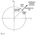
- the mean output amplitude (the modulus) is normalized to 1 without restricting the invention.
- the cost function becomes minimum when the deviation of the squared output amplitude from 1 is minimum. It is zero, when all complex output samples y(k) have the amplitude 1.
- the instantaneous error does not point to the correct direction, since only the radial component of the error can be determined.
- the information about the direction (phase) of the error is obtained again.
- a tap leakage is provided which causes a little deviation of the coefficients from their optimum values in the case of a distorting channel, but makes sure that with a flat channel, the coefficients do not diverge too much from their nominal position.
- 2 ⁇ 1 ⁇ ⁇ y I ( k ) e Q ( k ) ⁇
- the multiplication can also be performed with the sign of y I respectively y Q .
- the structure of the error detector which implements the equations above for the case of a normalization of the output amplitude to 1 is shown in Fig. 4.
- the input signals y I (k) and y Q (k), respectively, are each fed to a squarer in the form of multipliers 31 and33, respectively.
- the squared signals are added in an adder 35. From this sum, a constant, here 1, is subtracted in another adder 37.
- the result is multiplied in two multipliers with the input signals y I (k) and y Q (k), respectively, in order to form the instantaneous errors e I (k) and e Q (k) , respectively.
- Fig. 5 and Fig. 6 show the upper level structure of the correlator, whereas Fig. 7 shows the details of a correlation cell.
- the I and Q samples of the reference signal input are fed to two delay units 30a and 30b in order to compensate for the basic delay of the filter 24.
- the output signals of unit 30a are supplied, as I reference values, to the first inputs of respective correlation units 38 and 40, whereas the output signals of unit 30b are supplied, as Q reference values, to the first inputs of respective correlation units 42' and 44.
- the second inputs of correlation units 38 and 42 have coupled thereto the I error signal, whereas the second inputs of correlation units 40 and 44 have coupled thereto the Q error signal.
- the structure of the correlation units follows Fig. 6. For an N-tap equalizer they consist in the illustrated manner of N correlation cells 46 and N-1 delay elements 48. By correlating reference values and error values, the coefficients for the filter 24 are adapted.
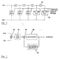
- Fig. 7 shows the structure of a correlation cell 46.
- the error signal e(k) and the reference signal r(k) are multiplied in a multiplier 50.
- the resulting product is then amplified or attenuated in some unit 52.
- an adder 54 By an adder 54, a tap-leakage value is subtracted from this signal.
- the tap-leakage value is supplied by an adaptation unit 56 which adjusts the tap-leakage value, depending on the coefficient, to an appropriate value.
- the output signal of the adder 54 is then accumulated in a resettable accumulator 58 with saturation and supplied as coefficient to the filter 24.
- tap leakage makes the filter coefficients return to a predetermined value if there exist no or only small correlation contributions. It is achieved by a subtraction (adder 54) of a small part of the accumulator output value. If the leakage values lie e.g. in the order of 2 -20 , the accumulator word length can be still kept small when the tap leakage value is not subtracted in every cycle, but e.g. only every 16th cycle. In this case the accumulator can be shortened by 4 bits with respect to a solution with a subtraction every cycle.
- the tap leakage can be set differently for each tap.
- the equalizer in accordance with the invention improves the system behavior mainly in two ways:
- Fig. 8 the improving effect of the equalizer to two-path fadings is shown in a signature measurement. Without equalizer the minimum signature depth is 10 dB, whereas with equalizer the minimum is increased to 18 dB.
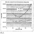
- Fig. 9 shows the improving effect on demodulator mistuning: Errors in the 90° phase tuning of the I/Q demodulator or relative gain differences between I and Q normally cause a distortion of the received signal. A circle in the I/Q plane would be transformed to an ellipse. Without countermeasures, this results in a phase error leading to an increased bit error rate.
- Fig. 9 illustrate that the CMA equalizer can compensate a phase error of ⁇ 15° without substantial degradation. Since there is a direct relation between the gain difference and the phase error (a phase error of 15° corresponds to approximately 2.3 dB gain difference), the same holds accordingly for the compensation of I/Q gain differences.
Landscapes
- Engineering & Computer Science (AREA)
- Power Engineering (AREA)
- Computer Networks & Wireless Communication (AREA)
- Signal Processing (AREA)
- Cable Transmission Systems, Equalization Of Radio And Reduction Of Echo (AREA)
Claims (11)
- Verfahren zur Entzerrung linear verzerrter Signale unter Verwendung eines Entzerrungsfilters, mit- adaptiver Filterung CPM-modulierter Signale zur Entzerrung der Signale;- Adaptierung der Filterkoeffizienten aufgrund von momentanen Fehlern e(k), die aus dem Filterausgangssignal aufgrund einer Entscheidung unter Anwendung eines Konstant-Modulus-Kriteriums abgeleitet werden;- Rückführung der Filterkoeffizienten mit einer vorbestimmten Zeitkonstante auf einen vorbestimmten Wert.
- Verfahren nach Anspruch 1, bei dem- die momentanen Fehler e(k) mit einem Referenzsignal korreliert werden;- das Korrelationsausgangssignal einem Akkumulator zur Bildung des Filterkoeffizienten zugeführt wird;- und das Ausgangssignal des Akkumulators zur Rückführung des Koeffizienten auf einen vorbestimmten Wert zurückgekoppelt wird.
- Verfahren nach Anspruch 2, bei dem die Verstärkung des rückgekoppelten Anteils des Akkumulatorausgangssignals für jeden Filterkoeffizienten anders eingestellt wird.
- Verfahren nach Anspruch 2, bei dem die Rückkopplung nur in jedem n-ten Zyklus erfolgt.
- Verfahren nach Anspruch 2, bei dem das rückgekoppelte Signal ein kleiner Teil des Akkumulatorausgangssignals ist und von dem Filtereingangssignal subtrahiert wird.
- Verfahren nach Anspruch 3, bei dem als Referenzsignal das Eingangssignal des Filters (24) benutzt wird.
- Verfahren nach Anspruch 3, bei dem als Referenzsignal das Ausgangssignal des Filters (24) benutzt wird.
- Vorrichtung zur Entzerrung linear verzerrter Signale unter Verwendung eines Entzerrungsfilters, enthaltend zur Verarbeitung übertragener CPM-modulierter Signale- ein adaptives Filter (24), dessen Koeffizienten von einer Adaptionseinheit (28) bestimmt sind;- einen mit dem Filterausgang verbundenen Fehlerdetektor (26) zur Erzeugung eines momentanen Fehlers e(k) aufgrund eines Konstant-Modulus-Kriteriums, der einer Adaptionseinheit (28) zugeführt wird, und- eine Einrichtung, welche die Filterkonstanten mit einer vorbestimmten Zeitkonstante auf einen vorbestimmten Wert zurückführt.
- Vorrichtung nach Anspruch 8, mit- einer Korrelationseinheit zur Korrelierung des momentanen Fehlers e(k) mit einem Referenzsignal;- einem Akkumulator, dem das Korrelator-Ausgangssignal zur Bildung des Filterkoeffizienten zugeführt wird;- einer Einrichtung zur Rückführung des Akkumulatorausgangssignals, um die Koeffizienten auf einen vorbestimmten Wert zurückzubringen.
- Vorrichtung nach Anspruch 9, in der das Referenzsignal durch das Eingangssignal des Filters (24) gebildet wird.
- Vorrichtung nach Anspruch 9, in der das Referenzsignal durch das Ausgangssignals des adaptiven Filters (24) gebildet wird.
Priority Applications (1)
| Application Number | Priority Date | Filing Date | Title |
|---|---|---|---|
| AT00935187T ATE319223T1 (de) | 2000-06-07 | 2000-06-07 | Verfahren und vorrichtung zur entzerrung von linear verzerrten signalen |
Applications Claiming Priority (1)
| Application Number | Priority Date | Filing Date | Title |
|---|---|---|---|
| PCT/EP2000/005268 WO2001095488A1 (en) | 2000-06-07 | 2000-06-07 | Method and apparatus for the equalization of linearly distorted signals |
Publications (2)
| Publication Number | Publication Date |
|---|---|
| EP1290792A1 EP1290792A1 (de) | 2003-03-12 |
| EP1290792B1 true EP1290792B1 (de) | 2006-03-01 |
Family
ID=8163979
Family Applications (1)
| Application Number | Title | Priority Date | Filing Date |
|---|---|---|---|
| EP00935187A Expired - Lifetime EP1290792B1 (de) | 2000-06-07 | 2000-06-07 | Verfahren und vorrichtung zur entzerrung von linear verzerrten signalen |
Country Status (3)
| Country | Link |
|---|---|
| EP (1) | EP1290792B1 (de) |
| DE (1) | DE60026298T2 (de) |
| WO (1) | WO2001095488A1 (de) |
-
2000
- 2000-06-07 EP EP00935187A patent/EP1290792B1/de not_active Expired - Lifetime
- 2000-06-07 DE DE60026298T patent/DE60026298T2/de not_active Expired - Lifetime
- 2000-06-07 WO PCT/EP2000/005268 patent/WO2001095488A1/en not_active Ceased
Also Published As
| Publication number | Publication date |
|---|---|
| WO2001095488A1 (en) | 2001-12-13 |
| EP1290792A1 (de) | 2003-03-12 |
| DE60026298T2 (de) | 2007-06-06 |
| DE60026298D1 (de) | 2006-04-27 |
Similar Documents
| Publication | Publication Date | Title |
|---|---|---|
| US7263144B2 (en) | Method and system for digital equalization of non-linear distortion | |
| US6741663B1 (en) | Linearization method for amplifier, and amplifier arrangement | |
| US6151368A (en) | Phase-noise compensated digital communication receiver and method therefor | |
| US6771720B1 (en) | Amplification control scheme for a receiver | |
| EP1956783B1 (de) | Verfahren und Vorrichtung zur Verwendung bei einer Entscheidungsrückgekoppelten Entzerrung | |
| US6606484B1 (en) | Distortion correction circuit for direct conversion receiver | |
| US8798196B2 (en) | Peak-to-average power ratio reduction for hybrid FM HD radio transmission | |
| US20050180527A1 (en) | Digital predistorter using power series model | |
| US6205170B1 (en) | Transmission/reception unit with bidirectional equalization | |
| US7026873B2 (en) | LMS-based adaptive pre-distortion for enhanced power amplifier efficiency | |
| US20090323856A1 (en) | Transmit-canceling transceiver responsive to heat signal and method therefor | |
| KR101093864B1 (ko) | 자동 선형 및 비선형 왜곡 보상 장치 및 방법 | |
| US10230353B2 (en) | Nonlinear signal filtering | |
| WO2002032067A1 (en) | Method for automatic frequency control | |
| EP1175762B1 (de) | Kommunikationssystem mit vorverzerrung | |
| JP5147089B2 (ja) | Ofdm通信システムにおけるアナログ損失のハイブリッドドメイン補償パラメータの求め方と補償方法 | |
| EP2765746B1 (de) | Verfahren und vorrichtung zur verarbeitung von daten | |
| US8233562B2 (en) | System and method for closed-loop signal distortion | |
| EP1290792B1 (de) | Verfahren und vorrichtung zur entzerrung von linear verzerrten signalen | |
| JPH0983417A (ja) | 無線機 | |
| CN101710887A (zh) | 一种数字预失真处理方法及系统 | |
| Huang et al. | Joint estimation of transmitter IQ imbalance and nonlinearity with multipath in OFDM systems | |
| JPH0787411B2 (ja) | 等化器 | |
| US8260229B2 (en) | I-Q mismatch compensation | |
| US20260032030A1 (en) | Demodulation |
Legal Events
| Date | Code | Title | Description |
|---|---|---|---|
| PUAI | Public reference made under article 153(3) epc to a published international application that has entered the european phase |
Free format text: ORIGINAL CODE: 0009012 |
|
| 17P | Request for examination filed |
Effective date: 20021204 |
|
| AK | Designated contracting states |
Kind code of ref document: A1 Designated state(s): AT BE CH CY DE DK ES FI FR GB GR IE IT LI LU MC NL PT SE |
|
| RAP1 | Party data changed (applicant data changed or rights of an application transferred) |
Owner name: SIEMENS MOBILE COMMUNICATIONS S.P.A. |
|
| GRAP | Despatch of communication of intention to grant a patent |
Free format text: ORIGINAL CODE: EPIDOSNIGR1 |
|
| GRAS | Grant fee paid |
Free format text: ORIGINAL CODE: EPIDOSNIGR3 |
|
| GRAA | (expected) grant |
Free format text: ORIGINAL CODE: 0009210 |
|
| AK | Designated contracting states |
Kind code of ref document: B1 Designated state(s): AT BE CH CY DE DK ES FI FR GB GR IE IT LI LU MC NL PT SE |
|
| PG25 | Lapsed in a contracting state [announced via postgrant information from national office to epo] |
Ref country code: AT Free format text: LAPSE BECAUSE OF FAILURE TO SUBMIT A TRANSLATION OF THE DESCRIPTION OR TO PAY THE FEE WITHIN THE PRESCRIBED TIME-LIMIT Effective date: 20060301 Ref country code: FI Free format text: LAPSE BECAUSE OF FAILURE TO SUBMIT A TRANSLATION OF THE DESCRIPTION OR TO PAY THE FEE WITHIN THE PRESCRIBED TIME-LIMIT Effective date: 20060301 Ref country code: NL Free format text: LAPSE BECAUSE OF FAILURE TO SUBMIT A TRANSLATION OF THE DESCRIPTION OR TO PAY THE FEE WITHIN THE PRESCRIBED TIME-LIMIT Effective date: 20060301 Ref country code: LI Free format text: LAPSE BECAUSE OF FAILURE TO SUBMIT A TRANSLATION OF THE DESCRIPTION OR TO PAY THE FEE WITHIN THE PRESCRIBED TIME-LIMIT Effective date: 20060301 Ref country code: CH Free format text: LAPSE BECAUSE OF FAILURE TO SUBMIT A TRANSLATION OF THE DESCRIPTION OR TO PAY THE FEE WITHIN THE PRESCRIBED TIME-LIMIT Effective date: 20060301 Ref country code: BE Free format text: LAPSE BECAUSE OF FAILURE TO SUBMIT A TRANSLATION OF THE DESCRIPTION OR TO PAY THE FEE WITHIN THE PRESCRIBED TIME-LIMIT Effective date: 20060301 |
|
| REG | Reference to a national code |
Ref country code: GB Ref legal event code: FG4D |
|
| REG | Reference to a national code |
Ref country code: CH Ref legal event code: EP |
|
| REG | Reference to a national code |
Ref country code: IE Ref legal event code: FG4D |
|
| REF | Corresponds to: |
Ref document number: 60026298 Country of ref document: DE Date of ref document: 20060427 Kind code of ref document: P |
|
| PG25 | Lapsed in a contracting state [announced via postgrant information from national office to epo] |
Ref country code: DK Free format text: LAPSE BECAUSE OF FAILURE TO SUBMIT A TRANSLATION OF THE DESCRIPTION OR TO PAY THE FEE WITHIN THE PRESCRIBED TIME-LIMIT Effective date: 20060601 Ref country code: SE Free format text: LAPSE BECAUSE OF FAILURE TO SUBMIT A TRANSLATION OF THE DESCRIPTION OR TO PAY THE FEE WITHIN THE PRESCRIBED TIME-LIMIT Effective date: 20060601 |
|
| PG25 | Lapsed in a contracting state [announced via postgrant information from national office to epo] |
Ref country code: IE Free format text: LAPSE BECAUSE OF NON-PAYMENT OF DUE FEES Effective date: 20060607 |
|
| PG25 | Lapsed in a contracting state [announced via postgrant information from national office to epo] |
Ref country code: ES Free format text: LAPSE BECAUSE OF FAILURE TO SUBMIT A TRANSLATION OF THE DESCRIPTION OR TO PAY THE FEE WITHIN THE PRESCRIBED TIME-LIMIT Effective date: 20060612 |
|
| RAP2 | Party data changed (patent owner data changed or rights of a patent transferred) |
Owner name: SIEMENS S.P.A. |
|
| PG25 | Lapsed in a contracting state [announced via postgrant information from national office to epo] |
Ref country code: MC Free format text: LAPSE BECAUSE OF NON-PAYMENT OF DUE FEES Effective date: 20060630 |
|
| NLT2 | Nl: modifications (of names), taken from the european patent patent bulletin |
Owner name: SIEMENS S.P.A. Effective date: 20060621 |
|
| PG25 | Lapsed in a contracting state [announced via postgrant information from national office to epo] |
Ref country code: PT Free format text: LAPSE BECAUSE OF FAILURE TO SUBMIT A TRANSLATION OF THE DESCRIPTION OR TO PAY THE FEE WITHIN THE PRESCRIBED TIME-LIMIT Effective date: 20060801 |
|
| NLV1 | Nl: lapsed or annulled due to failure to fulfill the requirements of art. 29p and 29m of the patents act | ||
| REG | Reference to a national code |
Ref country code: CH Ref legal event code: PL |
|
| ET | Fr: translation filed | ||
| PLBE | No opposition filed within time limit |
Free format text: ORIGINAL CODE: 0009261 |
|
| STAA | Information on the status of an ep patent application or granted ep patent |
Free format text: STATUS: NO OPPOSITION FILED WITHIN TIME LIMIT |
|
| 26N | No opposition filed |
Effective date: 20061204 |
|
| PG25 | Lapsed in a contracting state [announced via postgrant information from national office to epo] |
Ref country code: GR Free format text: LAPSE BECAUSE OF FAILURE TO SUBMIT A TRANSLATION OF THE DESCRIPTION OR TO PAY THE FEE WITHIN THE PRESCRIBED TIME-LIMIT Effective date: 20060602 |
|
| PG25 | Lapsed in a contracting state [announced via postgrant information from national office to epo] |
Ref country code: LU Free format text: LAPSE BECAUSE OF NON-PAYMENT OF DUE FEES Effective date: 20060607 |
|
| PG25 | Lapsed in a contracting state [announced via postgrant information from national office to epo] |
Ref country code: CY Free format text: LAPSE BECAUSE OF FAILURE TO SUBMIT A TRANSLATION OF THE DESCRIPTION OR TO PAY THE FEE WITHIN THE PRESCRIBED TIME-LIMIT Effective date: 20060301 |
|
| REG | Reference to a national code |
Ref country code: GB Ref legal event code: 732E Free format text: REGISTERED BETWEEN 20120719 AND 20120725 |
|
| REG | Reference to a national code |
Representative=s name: KUTZENBERGER WOLFF & PARTNER PATENTANWALTSPART, DE Ref country code: DE Ref legal event code: R082 Ref document number: 60026298 Country of ref document: DE |
|
| REG | Reference to a national code |
Ref country code: DE Ref legal event code: R081 Ref document number: 60026298 Country of ref document: DE Owner name: NOKIA SIEMENS NETWORKS ITALIA S.P.A., IT Free format text: FORMER OWNER: SIEMENS S.P.A., MAILAND/MILANO, IT Effective date: 20130620 Ref country code: DE Ref legal event code: R081 Ref document number: 60026298 Country of ref document: DE Owner name: DRAGONWAVE S.A R.L., LU Free format text: FORMER OWNER: SIEMENS S.P.A., MAILAND/MILANO, IT Effective date: 20130620 |
|
| PGFP | Annual fee paid to national office [announced via postgrant information from national office to epo] |
Ref country code: FR Payment date: 20130703 Year of fee payment: 14 |
|
| REG | Reference to a national code |
Ref country code: FR Ref legal event code: ST Effective date: 20150227 |
|
| PG25 | Lapsed in a contracting state [announced via postgrant information from national office to epo] |
Ref country code: FR Free format text: LAPSE BECAUSE OF NON-PAYMENT OF DUE FEES Effective date: 20140630 |
|
| REG | Reference to a national code |
Ref country code: FR Ref legal event code: TP Owner name: SIEMENS S.P.A., IT Effective date: 20151130 |
|
| REG | Reference to a national code |
Ref country code: DE Ref legal event code: R081 Ref document number: 60026298 Country of ref document: DE Owner name: DRAGONWAVE S.A R.L., LU Free format text: FORMER OWNER: NOKIA SIEMENS NETWORKS ITALIA S.P.A., CASSINA DE PECCHI, IT |
|
| PGFP | Annual fee paid to national office [announced via postgrant information from national office to epo] |
Ref country code: GB Payment date: 20170620 Year of fee payment: 18 Ref country code: DE Payment date: 20170621 Year of fee payment: 18 |
|
| PGFP | Annual fee paid to national office [announced via postgrant information from national office to epo] |
Ref country code: IT Payment date: 20170622 Year of fee payment: 18 |
|
| REG | Reference to a national code |
Ref country code: DE Ref legal event code: R119 Ref document number: 60026298 Country of ref document: DE |
|
| GBPC | Gb: european patent ceased through non-payment of renewal fee |
Effective date: 20180607 |
|
| PG25 | Lapsed in a contracting state [announced via postgrant information from national office to epo] |
Ref country code: IT Free format text: LAPSE BECAUSE OF NON-PAYMENT OF DUE FEES Effective date: 20180607 Ref country code: GB Free format text: LAPSE BECAUSE OF NON-PAYMENT OF DUE FEES Effective date: 20180607 Ref country code: DE Free format text: LAPSE BECAUSE OF NON-PAYMENT OF DUE FEES Effective date: 20190101 |