EP1290480B1 - Faseroptische stecker für bohrlochanwendungen - Google Patents
Faseroptische stecker für bohrlochanwendungen Download PDFInfo
- Publication number
- EP1290480B1 EP1290480B1 EP01944146A EP01944146A EP1290480B1 EP 1290480 B1 EP1290480 B1 EP 1290480B1 EP 01944146 A EP01944146 A EP 01944146A EP 01944146 A EP01944146 A EP 01944146A EP 1290480 B1 EP1290480 B1 EP 1290480B1
- Authority
- EP
- European Patent Office
- Prior art keywords
- termini
- connector
- key
- fiber optic
- optic cable
- Prior art date
- Legal status (The legal status is an assumption and is not a legal conclusion. Google has not performed a legal analysis and makes no representation as to the accuracy of the status listed.)
- Expired - Lifetime
Links
- 239000000835 fiber Substances 0.000 title claims description 53
- 238000003466 welding Methods 0.000 claims description 10
- 230000013011 mating Effects 0.000 claims description 5
- 230000001681 protective effect Effects 0.000 claims description 4
- 238000000034 method Methods 0.000 claims 1
- 238000005538 encapsulation Methods 0.000 description 3
- 229910052751 metal Inorganic materials 0.000 description 3
- 239000002184 metal Substances 0.000 description 3
- QAOWNCQODCNURD-UHFFFAOYSA-N Sulfuric acid Chemical compound OS(O)(=O)=O QAOWNCQODCNURD-UHFFFAOYSA-N 0.000 description 2
- DMFGNRRURHSENX-UHFFFAOYSA-N beryllium copper Chemical compound [Be].[Cu] DMFGNRRURHSENX-UHFFFAOYSA-N 0.000 description 2
- 238000003780 insertion Methods 0.000 description 2
- 230000037431 insertion Effects 0.000 description 2
- 239000004593 Epoxy Substances 0.000 description 1
- 229910045601 alloy Inorganic materials 0.000 description 1
- 239000000956 alloy Substances 0.000 description 1
- 239000003518 caustics Substances 0.000 description 1
- 230000007797 corrosion Effects 0.000 description 1
- 238000005260 corrosion Methods 0.000 description 1
- 231100001010 corrosive Toxicity 0.000 description 1
- 230000009477 glass transition Effects 0.000 description 1
- 229910000816 inconels 718 Inorganic materials 0.000 description 1
- 238000009434 installation Methods 0.000 description 1
- 239000000463 material Substances 0.000 description 1
- 238000012986 modification Methods 0.000 description 1
- 230000004048 modification Effects 0.000 description 1
- 230000003287 optical effect Effects 0.000 description 1
- 238000004806 packaging method and process Methods 0.000 description 1
- 230000036316 preload Effects 0.000 description 1
- 230000002035 prolonged effect Effects 0.000 description 1
- XLYOFNOQVPJJNP-UHFFFAOYSA-N water Substances O XLYOFNOQVPJJNP-UHFFFAOYSA-N 0.000 description 1
Images



Classifications
-
- G—PHYSICS
- G02—OPTICS
- G02B—OPTICAL ELEMENTS, SYSTEMS OR APPARATUS
- G02B6/00—Light guides; Structural details of arrangements comprising light guides and other optical elements, e.g. couplings
- G02B6/24—Coupling light guides
- G02B6/36—Mechanical coupling means
- G02B6/38—Mechanical coupling means having fibre to fibre mating means
- G02B6/3807—Dismountable connectors, i.e. comprising plugs
- G02B6/3873—Connectors using guide surfaces for aligning ferrule ends, e.g. tubes, sleeves, V-grooves, rods, pins, balls
- G02B6/3882—Connectors using guide surfaces for aligning ferrule ends, e.g. tubes, sleeves, V-grooves, rods, pins, balls using rods, pins or balls to align a pair of ferrule ends
- G02B6/3883—Connectors using guide surfaces for aligning ferrule ends, e.g. tubes, sleeves, V-grooves, rods, pins, balls using rods, pins or balls to align a pair of ferrule ends using rods, pins or balls to align a plurality of pairs of ferrule ends
-
- G—PHYSICS
- G02—OPTICS
- G02B—OPTICAL ELEMENTS, SYSTEMS OR APPARATUS
- G02B6/00—Light guides; Structural details of arrangements comprising light guides and other optical elements, e.g. couplings
- G02B6/24—Coupling light guides
- G02B6/36—Mechanical coupling means
- G02B6/38—Mechanical coupling means having fibre to fibre mating means
- G02B6/3807—Dismountable connectors, i.e. comprising plugs
- G02B6/381—Dismountable connectors, i.e. comprising plugs of the ferrule type, e.g. fibre ends embedded in ferrules, connecting a pair of fibres
- G02B6/3826—Dismountable connectors, i.e. comprising plugs of the ferrule type, e.g. fibre ends embedded in ferrules, connecting a pair of fibres characterised by form or shape
- G02B6/3831—Dismountable connectors, i.e. comprising plugs of the ferrule type, e.g. fibre ends embedded in ferrules, connecting a pair of fibres characterised by form or shape comprising a keying element on the plug or adapter, e.g. to forbid wrong connection
-
- G—PHYSICS
- G02—OPTICS
- G02B—OPTICAL ELEMENTS, SYSTEMS OR APPARATUS
- G02B6/00—Light guides; Structural details of arrangements comprising light guides and other optical elements, e.g. couplings
- G02B6/24—Coupling light guides
- G02B6/36—Mechanical coupling means
- G02B6/38—Mechanical coupling means having fibre to fibre mating means
- G02B6/3807—Dismountable connectors, i.e. comprising plugs
- G02B6/3873—Connectors using guide surfaces for aligning ferrule ends, e.g. tubes, sleeves, V-grooves, rods, pins, balls
- G02B6/3874—Connectors using guide surfaces for aligning ferrule ends, e.g. tubes, sleeves, V-grooves, rods, pins, balls using tubes, sleeves to align ferrules
- G02B6/3878—Connectors using guide surfaces for aligning ferrule ends, e.g. tubes, sleeves, V-grooves, rods, pins, balls using tubes, sleeves to align ferrules comprising a plurality of ferrules, branching and break-out means
-
- G—PHYSICS
- G02—OPTICS
- G02B—OPTICAL ELEMENTS, SYSTEMS OR APPARATUS
- G02B6/00—Light guides; Structural details of arrangements comprising light guides and other optical elements, e.g. couplings
- G02B6/24—Coupling light guides
- G02B6/36—Mechanical coupling means
- G02B6/38—Mechanical coupling means having fibre to fibre mating means
- G02B6/3807—Dismountable connectors, i.e. comprising plugs
- G02B6/381—Dismountable connectors, i.e. comprising plugs of the ferrule type, e.g. fibre ends embedded in ferrules, connecting a pair of fibres
- G02B6/3816—Dismountable connectors, i.e. comprising plugs of the ferrule type, e.g. fibre ends embedded in ferrules, connecting a pair of fibres for use under water, high pressure connectors
-
- G—PHYSICS
- G02—OPTICS
- G02B—OPTICAL ELEMENTS, SYSTEMS OR APPARATUS
- G02B6/00—Light guides; Structural details of arrangements comprising light guides and other optical elements, e.g. couplings
- G02B6/24—Coupling light guides
- G02B6/36—Mechanical coupling means
- G02B6/38—Mechanical coupling means having fibre to fibre mating means
- G02B6/3807—Dismountable connectors, i.e. comprising plugs
- G02B6/381—Dismountable connectors, i.e. comprising plugs of the ferrule type, e.g. fibre ends embedded in ferrules, connecting a pair of fibres
- G02B6/3818—Dismountable connectors, i.e. comprising plugs of the ferrule type, e.g. fibre ends embedded in ferrules, connecting a pair of fibres of a low-reflection-loss type
- G02B6/3822—Dismountable connectors, i.e. comprising plugs of the ferrule type, e.g. fibre ends embedded in ferrules, connecting a pair of fibres of a low-reflection-loss type with beveled fibre ends
-
- G—PHYSICS
- G02—OPTICS
- G02B—OPTICAL ELEMENTS, SYSTEMS OR APPARATUS
- G02B6/00—Light guides; Structural details of arrangements comprising light guides and other optical elements, e.g. couplings
- G02B6/24—Coupling light guides
- G02B6/36—Mechanical coupling means
- G02B6/38—Mechanical coupling means having fibre to fibre mating means
- G02B6/3807—Dismountable connectors, i.e. comprising plugs
- G02B6/3833—Details of mounting fibres in ferrules; Assembly methods; Manufacture
- G02B6/3847—Details of mounting fibres in ferrules; Assembly methods; Manufacture with means preventing fibre end damage, e.g. recessed fibre surfaces
-
- G—PHYSICS
- G02—OPTICS
- G02B—OPTICAL ELEMENTS, SYSTEMS OR APPARATUS
- G02B6/00—Light guides; Structural details of arrangements comprising light guides and other optical elements, e.g. couplings
- G02B6/24—Coupling light guides
- G02B6/36—Mechanical coupling means
- G02B6/38—Mechanical coupling means having fibre to fibre mating means
- G02B6/3807—Dismountable connectors, i.e. comprising plugs
- G02B6/3833—Details of mounting fibres in ferrules; Assembly methods; Manufacture
- G02B6/3851—Ferrules having keying or coding means
-
- G—PHYSICS
- G02—OPTICS
- G02B—OPTICAL ELEMENTS, SYSTEMS OR APPARATUS
- G02B6/00—Light guides; Structural details of arrangements comprising light guides and other optical elements, e.g. couplings
- G02B6/24—Coupling light guides
- G02B6/36—Mechanical coupling means
- G02B6/38—Mechanical coupling means having fibre to fibre mating means
- G02B6/3807—Dismountable connectors, i.e. comprising plugs
- G02B6/389—Dismountable connectors, i.e. comprising plugs characterised by the method of fastening connecting plugs and sockets, e.g. screw- or nut-lock, snap-in, bayonet type
- G02B6/3894—Screw-lock type
Definitions
- the present invention relates to connectors for fiber optic cables and, more particularly, to multi-channel connectors therefor that can be used in downhole applications and withstand high temperature and pressure.
- Fiber optic cables have been increasingly used for downhole oil and gas explorations. Specifically, the fiber optic cable is lowered into the well to transmit various information and data to the surface.
- the fiber optic cable is typically housed in at least one protective tube to shield the fiber optic from the extremely harsh downhole environment.
- the fiber optic cable can be subjected to downhole ambient pressures of approximately one thousand (1,000) atmospheres and temperatures ranging from 0°C to 175°C (zero to one hundred seventy-five degrees Celsius). Additionally, the fiber optic cable is exposed to downhole corrosives such as water, sulfuric acid and others.
- fiber optic cable in the downhole applications.
- packaging for fiber optic cable must be extremely compact for downhole use.
- the fiber optic cable must come either in extremely long segments or be connected. For installation and assembly purposes, it is much easier to have smaller segments of fiber optic cable that connect to each other.
- the connectors for the fiber optic cable must ensure integrity of the transmitted data and information as well as withstand the harsh ambient conditions of the downhole environment.
- Certain single channel connectors are commercially available with angled termini to reduce the return loss of a physical contact connector. These connectors are manufactured with the end surface of the termini polished at an angle such that the Fresnel reflection at the glass-air interface of the termini is reflected at an angle that exceeds the numerical aperture of the fiber. This allows the return loss (reflected energy) of the connector to be reproducibly suppressed by more than one million times or 60db.
- existing single-channel connectors are rated for temperatures ranging from -40°C to 85°C, which is substantially inadequate for downhole use.
- pressure rating of the single-channel angled physical contact connectors is not compatible for downhole use.
- the diameter of the angled termini is at least 2.5mm, which prohibits inclusion into multi-channel connectors that meet the dimensional requirements of the downhole environment.
- a connector for joining a first fiber optic cable end and a second fiber optic end of a fiber optic cable comprising: a first connector end adapted to receive said first fiber optic cable end; a second connector end adapted to receive said second fiber optic cable end; a first plurality of termini disposed within respective termini holes formed in said first connector end for terminating said first fiber optic cable end; a second plurality of termini disposed within respective termini holes formed in said second connector end for terminating said second fiber optic cable end, each termini of said first plurality of termini mating with each respective termini of said second plurality of termini; and a first alignment feature for properly aligning said first connector end with respect to said second connector end; wherein said first alignment feature comprises: at least one key opening formed on said first connector end; and at least one corresponding key protrusion formed on said second connector end adapted to fit into said at least one key opening to ensure proper alignment of said first and second connector ends; characterised in that each of the first plurality of termini and
- each termini includes an angled tip surface for mating with a corresponding termini such that the angled tip surfaces of mating termini are properly aligned with respect to each other as a result of the second alignment feature.
- the first alignment feature of the present invention also provides protection for the termini.
- the double alignment feature of the present invention allows the connector with multiple termini that require specific registration be properly aligned.
- the angled tip surface of the termini ensures improved connection between the fiber optic cable ends which in turn reduces unwanted reflections from the termini.
- a back-shell weld feature includes a welding surface and a capillary opening for facilitating welding of a protective capillary tube shielding the fiber optic cable to the ends of the connector.
- One major advantage of the present invention is that a multi-channel connector is sufficiently compact to be used for downhole applications.
- Another major advantage of the present invention is that the connector can withstand high temperatures and pressures.
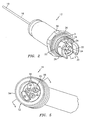
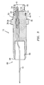
- a fiber optic connector 10 has a male connector end 12 and a female connector end 14 for joining a first fiber optic cable end 16 and a second fiber optic cable end 18 of a fiber optic cable 19.
- the fiber optic connector 10 also includes a make-up nut 20.
- the fiber optic cable 19 is shielded by a capillary encapsulation tube 21.
- the male connector end 12 includes a male housing 22 for housing a plurality of male termini 24 protruding outward from a surface 26.
- a first flange 28 and a second flange 30 also protrude outwardly from the surface 26 protecting the plurality of termini 24 and forming a first key opening 32 and a second key opening 34.
- the male housing 22 includes a lip 36 having a lip outside diameter 38 for accommodating a metal seal 39.
- the male housing 22 also has a male housing outside diameter 40 and includes a groove 42 for receiving an elastomeric O-ring 44, as best seen in FIG. 3 .
- the flanges 28, 30 have an outside flange diameter 46.
- each termini 24 is inserted into a keyed termini receiver hole 48 formed within the first connector end 12.
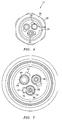
- the keyed termini receiver hole 48 includes a keyed slot 50, as best seen in FIG. 4 .
- Each termini 24 is used to terminate the fiber optic cable end 16.
- the female connector end 14 includes a female housing 52 having an outside surface 54 and a plurality of threads 56. A plurality of female termini 58 are disposed within the female housing 52.
- the housing 52 includes an inside diameter sized to accept the outside diameter 40 of the male housing 22.
- the female housing 52 also includes a first key protrusion 62 and a second key protrusion 64 adapted to be received within the first key opening 32 and the second key opening 34, respectively.
- the first key opening 32 and first key protrusion 62 are sized differently from the second key opening 34 and the second key protrusion 64 to ensure proper alignment between the male and female connector ends 12, 14 and, in combination, form a first alignment feature of the fiber optic connector 10.
- the key protrusions 62, 64 are of sufficient length to prevent engagement of the termini until proper angular alignment between the ends 12, 14 is achieved.
- the female housing 52 also includes a plurality of keyed termini holes 66 for accepting the plurality of female termini 58.
- Each termini hole 66 also includes a keyed slot 67 and has a sleeve 68 extending past the outward end of the termini 58.
- each termini 24, 58 has a central axis 70 and includes a base part 72 and a top part 74 with the top part 74 terminating with a tip surface 76.
- Each base part 72 of each termini 24, 58 includes a termini key 78.
- the termini key 78 is a pin 80 inserted in an opening 82 formed within the base part 72 and protruding outwardly therefrom.
- the tip surface 76 of each termini 24, 58 is angled and forms an angle a with a line perpendicular to the axis 70 of the termini 24, 58. In the preferred embodiment of the present invention, the angle a is approximately eight degrees (8°).
- the angled tip surface 76 at each termini 24 is formed to mate with the corresponding termini 58 when both termini 24, 58 are properly keyed into respective connector ends 12, 14. For higher numerical aperture fiber the angle ⁇ can be increased to approximately fifteen degrees (15°).
- each termini 24, 58 is inserted into the termini keyed hole 48, 66, respectively.
- Each termini key 78 fits into the corresponding keyed slot 50, 67 of the termini keyed hole 48, 66.
- the keyed termini slot 50, 67 and the termini key 78 of each termini 24, 58 define a second alignment feature of the fiber optic connector 10 which ensures that the male termini 24 is properly aligned with the female termini 58 for each particular termini connection.
- the make-up nut 20 is adapted to fit over the male connector end 12 and includes threads 84 on the inside thereof to mate with the threads 56 of the female connector end 14.
- the nut 20 is fabricated from beryllium copper (BeCu) and, when torqued to specifications, provides sufficient elasticity to prevent back-off.
- BeCu beryllium copper
- the male and female housings 22, 52 also include a back-shell weld feature 86 that incorporates a welding surface 88 and a capillary opening 90 adapted to receive ends of the capillary encapsulation tube 21.
- the female housing 52 can include threads 91 for receiving threaded tube or other equipment that cannot be welded, as best seen in FIG. 6 .
- the connector ends 12,14 are welded to the encapsulation tube 21 shielding the fiber optic cable 19.
- the ends of the capillary tube 21 are placed into the capillary opening 90 and welded at the welding surface 88 to attach the connector ends 12, 14 to the capillary tube 21.
- the first alignment feature 32, 34, 62, 64 ensures that the two connector ends 12,14 are properly aligned with respect to each other.
- the connector ends 12, 14 are rotated with respect to each other until the first key protrusion 62 and the second key protrusion 64 fit into the first key opening 32 and the second key opening 34, respectively.
- the plurality of male termini 24 fit into the plurality of sleeves 68 and slide to make connection with the female termini 58, as best seen in FIG.1 .
- the second alignment feature 50, 67, 78 ensures that each termini connection is properly made.
- the angled tip surface 76 of each female termini 58 registers with the angled tip surface 76 of the male termini 24, as both termini keys of termini 24, 58 are keyed into their respective slots 50, 67.
- the angled tip surface 76 of the termini 24, 58 ensures that retro-reflection is minimized.
- the make-up nut 20 is secured onto the female portion 14 of the connector 10 by having the threads 56, 84 mate.
- the metal seal 39 sandwiched between the male and female connector ends 12, 14, provides a primary level of seal protection.
- the O-ring seal 44 provides a secondary or back-up seal, should the metal seal 39 fail.
- the termini 24, 58 are a single channel termini, MEL-T-29504 equivalent, purchased from Packard-Hughes Interconnect Company that have a diameter of approximately two millimeters (2 mm) and have been further modified to include an approximately eight degree (8°) angle on the tip surface 76 thereof and to include the key 78 on the base part 72 thereof.
- the fiber optic connector 10 has two alignment features that allow multiple termini connections be made while ensuring proper alignment of each of these termini connections.
- Another major advantage of the present invention is that this multi-channel connector can be used in downhole applications.
- the connector 10 of the present invention can operate at temperatures ranging approximately from 0°C to 175°C (zero to one hundred seventy-five degrees Celsius) and ambient pressures of approximately one thousand (1,000) atmospheres.
- a further advantage of the present invention is that the back-shell weld feature 86 not only facilitates attachment of the connector ends 12, 14 onto the capillary tube, but also acts as both the strength element anchor for the fiber optic cable as well as the environment seal to prevent flooding of the cable.
- a number of features of the present invention contribute and ensure that this connector can be used in extremely harsh environment.
- One such feature is the choice of high strength, corrosion resistant alloys such as Inconel 718 and beryllium copper (BeCu).
- Another such feature is the thickness and material from which the nut 20 is manufactured. The elasticity of the make-up nut eliminates the need for safety wire or anti-rotation pawls.
Landscapes
- Physics & Mathematics (AREA)
- General Physics & Mathematics (AREA)
- Optics & Photonics (AREA)
- Mechanical Coupling Of Light Guides (AREA)
Claims (15)
- Steckverbinder zum Verbinden eines ersten Lichtwellenleiter-Kabelendes (16) und eines zweiten Lichtwellenleiter-Kabelendes (16) eines Lichtwellenleiter-Kabels (19), wobei der Steckverbinder Folgendes umfasst:ein erstes Steckverbinderende (12), das dafür eingerichtet ist, das erste Lichtwellenleiter-Kabelende (16) aufzunehmen,ein zweites Steckverbinderende (14), das dafür eingerichtet ist, das zweite Lichtwellenleiter-Kabelende (18) aufzunehmen,eine erste Vielzahl von Anschlüssen (24), die innerhalb jeweiliger, in dem ersten Steckverbinderende (12) geformten, Anschlusslöcher (48) angeordnet sind, um das erste Lichtwellenleiter-Kabelende (16) anzuschließen,eine zweite Vielzahl von Anschlüssen (58), die innerhalb jeweiliger, in dem zweiten Steckverbinderende (14) geformten, Anschlusslöcher (66) angeordnet sind, um das zweite Lichtwellenleiter-Kabelende (18) anzuschließen, wobei jeder Anschluss der ersten Vielzahl von Anschlüssen (24) mit jedem Anschluss der zweiten Vielzahl von Anschlüssen (58) zusammenpasst, undein erstes Ausrichtungsmerkmal (32, 34, 62, 64), um das erste Steckverbinderende (12) in Bezug auf das zweite Steckverbinderende (14) richtig auszurichten,wobei das erste Ausrichtungsmerkmal (32, 34, 62, 64) Folgendes umfasst: wenigstens eine, an dem ersten Steckverbinderende (12) geformte, Passöffnung (32, 34), und wenigstens ein, an dem zweiten Steckverbinderende (14) geformter, entsprechender Passvorsprung (62, 64), dafür eingerichtet, in die wenigstens eine Passöffnung (32, 34) zu passen, um eine richtige Ausrichtung des ersten und des zweiten Steckverbinderendes (12, 14) sicherzustellen,
wobei jeder der ersten Vielzahl von Anschlüssen und jeder der zweiten Vielzahl von Anschlüssen eine abgewinkelte Spitze umfasst,
und der ferner ein zweites Ausrichtungsmerkmal (50, 67, 78) umfasst, um jeden der ersten Vielzahl von Anschlüssen (24) richtig mit einem entsprechenden der zweiten Vielzahl von Anschlüssen (58) auszurichten,
dadurch gekennzeichnet, dass das zweite Ausrichtungsmerkmal (50, 67, 78) eine Vielzahl von Anschlusspassformen (78) umfasst, wobei jede Anschlusspassform (78) an einem jeweiligen der Vielzahl von Anschlüssen (24, 58) angeordnet ist, wobei jede Anschlusspassform (78) dafür eingerichtet ist, in einem Anschlusspassschlitz (50, 67) zu passen, der in dem ersten und dem zweiten Steckverbinderende (12, 14) geformt ist, um die Anschlüsse (24, 58) aufzunehmen,
und ferner dadurch gekennzeichnet, dass das erste und das zweite Ausrichtungsmerkmal (32, 34, 62, 64; 50, 67, 78) so eingerichtet sind, dass sie eine vorbestimmte und feststehende relative Winkelausrichtung zwischen den jeweiligen abgewinkelten Spitzen der ersten und der zweiten Anschlüsse (24, 58) definieren und jede der abgewinkelten Spitzen der ersten Vielzahl von Anschlüssen mit der entsprechenden abgewinkelten Spitze der zweiten Vielzahl von Anschlüssen zusammenpassen. - Steckverbinder nach Anspruch 1, der ferner eine Mutter (20) umfasst, die um das erste Steckverbinderende (12) angeordnet ist und schraubbar an dem zweiten Steckverbinderende (14) befestigt ist.
- Steckverbinder nach Anspruch 1 oder 2, der eine Vielzahl von Passöffnungen (32, 34), die an dem ersten Steckverbinderende (12) geformt sind, und eine entsprechende Vielzahl von Passvorsprüngen (62, 64), die an dem zweiten Steckverbinderende (14) geformt sind, umfasst.
- Steckverbinder nach Anspruch 3, der eine Vielzahl von Flanschen (28, 30) umfasst, um die Vielzahl von Passöffnungen (32, 34) zu definieren.
- Steckverbinder nach Anspruch 3 oder 4, wobei die Vielzahl von Passöffnungen (32, 34) eine erste Passöffnung (32) und eine zweite Passöffnung (34) umfasst, wobei die erste und die zweite Passöffnung (32, 34) unterschiedliche Größen haben und wobei die Vielzahl von Passvorsprüngen (62, 64) einen ersten Passvorsprung (62) und einen zweiten Passvorsprung (64) umfasst, die in der Größe der ersten bzw. der zweiten Passöffnung (32, 34) entsprechen.
- Steckverbinder nach einem der vorhergehenden Ansprüche, wobei jede Anschlusspassform (78) einen Stift (80) umfasst, der in einen Basisteil (72) von entsprechenden der Anschlüsse (24, 58) eingesteckt wird, wobei der Stift (80) dafür eingerichtet ist, in einen entsprechenden Anschlusspassschlitz (50, 67) zu passen.
- Steckverbinder nach einem der vorhergehenden Ansprüche, wobei jeder Anschluss (24, 58) eine abgewinkelte Spitzenfläche (76) zum Zusammenpassen mit einem entsprechenden Anschluss (24, 58) einschließt, wobei als Ergebnis des zweiten Ausrichtungsmerkmals (50, 67, 78) die abgewinkelten Spitzenflächen (76), wenn sie verbunden werden, richtig in Bezug auf einander ausgerichtet werden.
- Steckverbinder nach einem der vorhergehenden Ansprüche, wobei der Steckverbinder mehrkanalig ist.
- Steckverbinder nach einem der vorhergehenden Ansprüche, wobei der Steckverbinder dafür berechnet ist, Temperaturen zu widerstehen, die von ungefähr 0°C bis zu ungefähr 175°C reichen.
- Steckverbinder nach einem der vorhergehenden Ansprüche, wobei der Steckverbinder dafür berechnet ist, Umgebungsdrücken von ungefähr eintausend (1 000) Atmosphären zu widerstehen.
- Steckverbinder nach einem der vorhergehenden Ansprüche, wobei der Steckverbinder ferner ein Hinterschalen-Schweißmerkmal (86) umfasst, um ein Schweißen jedes der Steckverbinderenden (12, 14) an einen Schutzschlauch (21) des Lichtwellenleiter-Kabels (19) zu erleichtern.
- Steckverbinder nach Anspruch 11, wobei das Hinterschalen-Schweißmerkmal (86) Folgendes umfasst:eine innerhalb des Steckverbinderendes (12, 14) geformte Schweißöffnung (90), die dafür eingerichtet ist, den Schutzschlauch (21) aufzunehmen, undeine an einem Ende des Steckverbinderendes (12, 14) geformte Schweißfläche (88), die im Wesentlichen an die Schweißöffnung (90) anstößt.
- Steckverbinder nach einem der vorhergehenden Ansprüche, wobei das erste Steckverbinderende (12) ein Stecker-Steckverbinderende ist und das zweite Steckverbinderende (14) ein Buchsen-Steckverbinderende ist.
- Steckverbinder nach einem der vorhergehenden Ansprüche, wobei der Anschlusspassschlitz (50, 67) längs einer Länge des Anschluspasslochs (48, 66) geformt und dafür angeordnet ist, die Anschlusspassform (78) aufzunehmen, wenn der Anschluss (24, 58) während des Zusammenbaus des Steckverbinderendes (12, 14) in das Anschlusspassloch (48, 66) eingesteckt wird.
- Verfahren zum Aufbauen eines Steckverbinders nach einem der vorhergehenden Ansprüche, das umfasst, die abgewinkelten Spitzen der ersten Vielzahl von Anschlüssen (24) unabhängig vom Formen der abgewinkelten Spitzen der zweiten Vielzahl von Anschlüssen (58) zu formen.
Applications Claiming Priority (3)
| Application Number | Priority Date | Filing Date | Title |
|---|---|---|---|
| US594645 | 2000-06-15 | ||
| US09/594,645 US6685361B1 (en) | 2000-06-15 | 2000-06-15 | Fiber optic cable connectors for downhole applications |
| PCT/US2001/015792 WO2002025340A1 (en) | 2000-06-15 | 2001-05-16 | Fiber optic cable connectors for downhole applications |
Publications (2)
| Publication Number | Publication Date |
|---|---|
| EP1290480A1 EP1290480A1 (de) | 2003-03-12 |
| EP1290480B1 true EP1290480B1 (de) | 2009-07-22 |
Family
ID=24379775
Family Applications (1)
| Application Number | Title | Priority Date | Filing Date |
|---|---|---|---|
| EP01944146A Expired - Lifetime EP1290480B1 (de) | 2000-06-15 | 2001-05-16 | Faseroptische stecker für bohrlochanwendungen |
Country Status (5)
| Country | Link |
|---|---|
| US (2) | US6685361B1 (de) |
| EP (1) | EP1290480B1 (de) |
| CA (1) | CA2412625C (de) |
| DE (1) | DE60139315D1 (de) |
| WO (1) | WO2002025340A1 (de) |
Families Citing this family (55)
| Publication number | Priority date | Publication date | Assignee | Title |
|---|---|---|---|---|
| US9239441B2 (en) * | 2000-05-26 | 2016-01-19 | Corning Cable Systems Llc | Fiber optic drop cables and preconnectorized assemblies having toning portions |
| US6962445B2 (en) | 2003-09-08 | 2005-11-08 | Adc Telecommunications, Inc. | Ruggedized fiber optic connection |
| US7210856B2 (en) * | 2004-03-02 | 2007-05-01 | Welldynamics, Inc. | Distributed temperature sensing in deep water subsea tree completions |
| US7641395B2 (en) * | 2004-06-22 | 2010-01-05 | Halliburton Energy Serives, Inc. | Fiber optic splice housing and integral dry mate connector system |
| US7400803B2 (en) * | 2005-03-25 | 2008-07-15 | Welldynamics, B.V. | Method and apparatus for providing a hydrogen diffusion barrier for fiber optic cables used in hostile environments |
| US6907170B1 (en) | 2004-07-22 | 2005-06-14 | Halliburton Energy Services, Inc. | Hydrogen diffusion delay barrier for fiber optic cables used in hostile environments |
| US7218820B2 (en) * | 2004-07-22 | 2007-05-15 | Welldynamics, Inc. | Method and system for providing a hydrogen diffusion barrier for fiber optic cables used in hostile environments |
| US20060045428A1 (en) * | 2004-08-24 | 2006-03-02 | Thomas Theuerkorn | Fiber optic receptacle and plug assemblies |
| US7244066B2 (en) * | 2005-02-25 | 2007-07-17 | Corning Cable Systems Llc | Fiber optic receptacle and plug assembly including alignment sleeve insert |
| US7264402B2 (en) * | 2005-03-10 | 2007-09-04 | Corning Cable Systems Llc | Multi-fiber optic receptacle and plug assembly |
| US7572063B2 (en) * | 2005-09-12 | 2009-08-11 | Stratos International, Inc. | Opto-electric connector |
| US7604505B2 (en) * | 2006-02-27 | 2009-10-20 | Light Sources, Inc. | Ultraviolet lamp for use in water purifiers |
| US7795813B2 (en) * | 2006-02-27 | 2010-09-14 | Light Sources, Inc. | Ultraviolet lamp for use in water purifiers |
| US8021189B2 (en) * | 2006-02-27 | 2011-09-20 | Light Sources Inc. | Ultraviolet lamp for use in water purifiers |
| US7836959B2 (en) * | 2006-03-30 | 2010-11-23 | Schlumberger Technology Corporation | Providing a sensor array |
| GB2439946B (en) * | 2006-07-10 | 2010-06-23 | Schlumberger Holdings | Apparatus for forming an optical fiber device |
| US7572065B2 (en) * | 2007-01-24 | 2009-08-11 | Adc Telecommunications, Inc. | Hardened fiber optic connector |
| US7614797B2 (en) * | 2007-01-24 | 2009-11-10 | Adc Telecommunications, Inc. | Fiber optic connector mechanical interface converter |
| US7591595B2 (en) | 2007-01-24 | 2009-09-22 | Adc Telelcommunications, Inc. | Hardened fiber optic adapter |
| TWM317106U (en) * | 2007-02-16 | 2007-08-11 | Alltop Technology Co Ltd | Power connector |
| WO2008137897A1 (en) * | 2007-05-06 | 2008-11-13 | Adc Telecommunications, Inc. | Mechanical interface converter for making non-ruggedized fiber optic connectors compatible with a ruggedized fiber optic adapter |
| US7722258B2 (en) * | 2007-05-06 | 2010-05-25 | Adc Telecommunications, Inc. | Interface converter for SC fiber optic connectors |
| US7686519B2 (en) * | 2007-06-18 | 2010-03-30 | Adc Telecommunications, Inc. | Hardened fiber optic housing and cable assembly |
| US7744286B2 (en) | 2007-12-11 | 2010-06-29 | Adc Telecommunications, Inc. | Hardened fiber optic connection system with multiple configurations |
| US8403570B2 (en) * | 2008-04-10 | 2013-03-26 | Amphenol Corporation | Plural fiber optic interconnect |
| US8794337B2 (en) | 2009-02-18 | 2014-08-05 | Halliburton Energy Services, Inc. | Apparatus and method for controlling the connection and disconnection speed of downhole connectors |
| US8123547B2 (en) * | 2009-12-17 | 2012-02-28 | Knowles Electronics, Llc | Connector assembly |
| US8540435B2 (en) | 2011-07-22 | 2013-09-24 | Corning Cable Systems Llc | Ferrule retainers having access window(s) for accessing and/or referencing a fiber optic ferrule, and related fiber optic connector assemblies, connectors, and referencing methods |
| BR112015019096A2 (pt) * | 2013-03-01 | 2017-07-18 | Halliburton Energy Services Inc | conector de cabo de perfilagem incluindo um eletroímã e um metal |
| US9611734B2 (en) | 2013-05-21 | 2017-04-04 | Hallitburton Energy Services, Inc. | Connecting fiber optic cables |
| US10444443B2 (en) | 2013-06-27 | 2019-10-15 | CommScope Connectivity Belgium BVBA | Fiber optic cable anchoring device for use with fiber optic connectors and methods of using the same |
| WO2016143202A1 (ja) * | 2015-03-06 | 2016-09-15 | 株式会社フジクラ | プラグ側光コネクタ及び光コネクタシステム |
| US11300746B2 (en) | 2017-06-28 | 2022-04-12 | Corning Research & Development Corporation | Fiber optic port module inserts, assemblies and methods of making the same |
| US11187859B2 (en) | 2017-06-28 | 2021-11-30 | Corning Research & Development Corporation | Fiber optic connectors and methods of making the same |
| US10359577B2 (en) | 2017-06-28 | 2019-07-23 | Corning Research & Development Corporation | Multiports and optical connectors with rotationally discrete locking and keying features |
| US11668890B2 (en) | 2017-06-28 | 2023-06-06 | Corning Research & Development Corporation | Multiports and other devices having optical connection ports with securing features and methods of making the same |
| US12271040B2 (en) | 2017-06-28 | 2025-04-08 | Corning Research & Development Corporation | Fiber optic extender ports, assemblies and methods of making the same |
| EP3646092B1 (de) | 2017-06-28 | 2021-11-24 | Corning Research & Development Corporation | Kompakte glasfaserverbinder |
| MX2021006211A (es) | 2018-11-29 | 2021-08-11 | Corning Res & Dev Corp | Multipuertos y otros dispositivos que tienen puertos de conexion optica con accionadores giratorios y metodos de fabricacion de los mismos. |
| US10908364B2 (en) | 2019-02-08 | 2021-02-02 | Corning Research & Development Corporation | Fiber optic connectors with at least one field-installable termini |
| MX2021014427A (es) | 2019-05-31 | 2022-03-04 | Corning Res & Dev Corp | Multipuertos y otros dispositivos que tienen puertos de conexion optica con accionadores deslizantes y metodos para elaborar los mismos. |
| US11294133B2 (en) | 2019-07-31 | 2022-04-05 | Corning Research & Development Corporation | Fiber optic networks using multiports and cable assemblies with cable-to-connector orientation |
| EP3805827B1 (de) | 2019-10-07 | 2025-07-30 | Corning Research & Development Corporation | Faseroptische anschlüsse und faseroptische netzwerke mit kopplern mit variablem verhältnis |
| EP4045957B1 (de) | 2019-10-18 | 2023-12-13 | Corning Research & Development Corporation | Anschlüsse mit optischen anschlussöffnungen mit befestigungsmerkmalen zur bereitstellung stabiler haltekräfte |
| US11650388B2 (en) | 2019-11-14 | 2023-05-16 | Corning Research & Development Corporation | Fiber optic networks having a self-supporting optical terminal and methods of installing the optical terminal |
| US11536921B2 (en) | 2020-02-11 | 2022-12-27 | Corning Research & Development Corporation | Fiber optic terminals having one or more loopback assemblies |
| CA3184578A1 (en) | 2020-06-29 | 2022-01-06 | Michael De Jong | Terminals having a multi-fiber optical connection port that inhibits damage from single-fiber connectors |
| US11604320B2 (en) | 2020-09-30 | 2023-03-14 | Corning Research & Development Corporation | Connector assemblies for telecommunication enclosures |
| CN116601834A (zh) | 2020-10-30 | 2023-08-15 | 康宁研究与开发公司 | 具有防风雨套环的光纤连接器 |
| US11686913B2 (en) | 2020-11-30 | 2023-06-27 | Corning Research & Development Corporation | Fiber optic cable assemblies and connector assemblies having a crimp ring and crimp body and methods of fabricating the same |
| US11927810B2 (en) | 2020-11-30 | 2024-03-12 | Corning Research & Development Corporation | Fiber optic adapter assemblies including a conversion housing and a release member |
| US11994722B2 (en) | 2020-11-30 | 2024-05-28 | Corning Research & Development Corporation | Fiber optic adapter assemblies including an adapter housing and a locking housing |
| US11880076B2 (en) | 2020-11-30 | 2024-01-23 | Corning Research & Development Corporation | Fiber optic adapter assemblies including a conversion housing and a release housing |
| US11947167B2 (en) | 2021-05-26 | 2024-04-02 | Corning Research & Development Corporation | Fiber optic terminals and tools and methods for adjusting a split ratio of a fiber optic terminal |
| US20250035863A1 (en) * | 2023-07-28 | 2025-01-30 | Corning Research & Development Corporation | Fiber optic connectors with a retention body and methods of fabricating the same |
Citations (1)
| Publication number | Priority date | Publication date | Assignee | Title |
|---|---|---|---|---|
| US4140367A (en) * | 1976-10-08 | 1979-02-20 | Bunker Ramo Corporation | Multiple channel connector for fiber optic cables |
Family Cites Families (19)
| Publication number | Priority date | Publication date | Assignee | Title |
|---|---|---|---|---|
| US3945700A (en) * | 1974-08-06 | 1976-03-23 | Boston Insulated Wire & Cable Co. | Connector with fluid-resistant sleeve assembly |
| US4252406A (en) * | 1978-09-05 | 1981-02-24 | The United States Of America As Represented By The Secretary Of The Army | Connector for optical fibers |
| US4225214A (en) | 1978-09-18 | 1980-09-30 | Trw Inc. | Connector construction |
| US4759601A (en) | 1985-06-24 | 1988-07-26 | Schlumberger Technology Corporation | Fiber optic connector assembly |
| JPS6270805A (ja) | 1985-09-25 | 1987-04-01 | Furukawa Electric Co Ltd:The | 光・メタル複合ケ−ブル端末部 |
| EP0328553A4 (de) * | 1987-06-15 | 1989-10-25 | Bell Helicopter Textron Inc | Sich selbst ausrichtendes elektrisches verbindungsstück. |
| US4829407A (en) * | 1987-11-06 | 1989-05-09 | Oxley Developments Company Limited | Indicator lamps |
| US5018822A (en) | 1989-12-11 | 1991-05-28 | Litton Systems, Inc. | Environmentally sealed multichannel fiber optic connector |
| US5067783A (en) * | 1990-10-16 | 1991-11-26 | At&T Bell Laboratories | Optical fiber connector buildout system |
| US5064268A (en) | 1990-12-07 | 1991-11-12 | The United States Of America As Represented By The Secretary Of The Navy | High pressure fiber optic connector plug |
| US5293581A (en) * | 1993-04-16 | 1994-03-08 | Alcoa Fujikura Ltd. | Flexible connector assembly for fiber optics |
| US5301213A (en) | 1993-06-08 | 1994-04-05 | Combustion Engineering, Inc. | Method of field replacement of an electrical connector for nuclear reactor instrumentation |
| US5384885A (en) * | 1993-10-28 | 1995-01-24 | At&T Corp. | Variable attenuation optical fiber coupling |
| US5590229A (en) | 1994-04-22 | 1996-12-31 | Litton Systems, Inc. | Multichannel fiber optic connector |
| US5433275A (en) * | 1994-07-19 | 1995-07-18 | Baker Hughes Incorporated | Double-threaded anchor tubing assembly |
| US5928034A (en) * | 1996-07-30 | 1999-07-27 | Sumitomo Wiring Systems, Ltd. | Connector with terminal locking and locking assurance features |
| JP3330509B2 (ja) * | 1997-03-25 | 2002-09-30 | 矢崎総業株式会社 | コネクタ |
| US5925879A (en) * | 1997-05-09 | 1999-07-20 | Cidra Corporation | Oil and gas well packer having fiber optic Bragg Grating sensors for downhole insitu inflation monitoring |
| US6234683B1 (en) * | 1999-09-13 | 2001-05-22 | Stratos Lightwave, Inc. | Field repairable hermaphroditic connector |
-
2000
- 2000-06-15 US US09/594,645 patent/US6685361B1/en not_active Expired - Lifetime
-
2001
- 2001-05-16 CA CA002412625A patent/CA2412625C/en not_active Expired - Fee Related
- 2001-05-16 DE DE60139315T patent/DE60139315D1/de not_active Expired - Lifetime
- 2001-05-16 WO PCT/US2001/015792 patent/WO2002025340A1/en not_active Ceased
- 2001-05-16 EP EP01944146A patent/EP1290480B1/de not_active Expired - Lifetime
-
2004
- 2004-02-03 US US10/772,091 patent/US7052185B2/en not_active Expired - Lifetime
Patent Citations (1)
| Publication number | Priority date | Publication date | Assignee | Title |
|---|---|---|---|---|
| US4140367A (en) * | 1976-10-08 | 1979-02-20 | Bunker Ramo Corporation | Multiple channel connector for fiber optic cables |
Also Published As
| Publication number | Publication date |
|---|---|
| CA2412625A1 (en) | 2002-03-28 |
| WO2002025340A1 (en) | 2002-03-28 |
| US20040247251A1 (en) | 2004-12-09 |
| CA2412625C (en) | 2009-07-14 |
| DE60139315D1 (de) | 2009-09-03 |
| WO2002025340A8 (en) | 2002-05-23 |
| US6685361B1 (en) | 2004-02-03 |
| EP1290480A1 (de) | 2003-03-12 |
| US7052185B2 (en) | 2006-05-30 |
Similar Documents
| Publication | Publication Date | Title |
|---|---|---|
| EP1290480B1 (de) | Faseroptische stecker für bohrlochanwendungen | |
| US6206579B1 (en) | Arrangement for integrating a rectangular fiber optic connector into a cylindrical connector | |
| US6422759B1 (en) | Fiber optic connector | |
| CN102722003B (zh) | 光电连接器 | |
| TW542928B (en) | Termination device of a fiber optic cable/waveguide and tool for inserting/extracting a plug insert into/out of a housing of said termination device | |
| US6069992A (en) | Connector system with precision alignment | |
| US6062739A (en) | Fiber optic connector | |
| CN105122109B (zh) | 光学连接器组件 | |
| GB2341455A (en) | Cylindrical contact for fibre optic connector having parallelepiped shaped ferrule | |
| US8308501B2 (en) | Solid state lighting assembly having a strain relief member | |
| CN100580492C (zh) | 用于光波导体插接连接器的内壳 | |
| CN113093346A (zh) | 光缆组件及光纤连接器 | |
| US4690487A (en) | Hermetically sealed fiber optic connector | |
| EP0913888A2 (de) | Steckverbinder MIL-C-26500 und ARINC mit hoher Leistung | |
| JP3205833B2 (ja) | 光コネクタプラグ | |
| US20200386955A1 (en) | Outdoor optical fiber connector | |
| US5146524A (en) | Fibre optic connector | |
| CN101710197B (zh) | 光连接器及其组件 | |
| GB2124793A (en) | Fibre optic connector | |
| JP4932303B2 (ja) | 光通信用モジュール及びその製造方法 | |
| CN224081852U (zh) | 光纤推拉自锁式连接器 | |
| JP2009086562A (ja) | 光電変換回路内蔵型コネクタ | |
| WO1996038748A1 (en) | Fibre optic connector having compliant end face | |
| CN117930440A (zh) | 导光连接器、内窥镜系统 | |
| KR20120106616A (ko) | 다심 광커넥터 |
Legal Events
| Date | Code | Title | Description |
|---|---|---|---|
| PUAI | Public reference made under article 153(3) epc to a published international application that has entered the european phase |
Free format text: ORIGINAL CODE: 0009012 |
|
| 17P | Request for examination filed |
Effective date: 20021213 |
|
| AK | Designated contracting states |
Kind code of ref document: A1 Designated state(s): AT BE CH CY DE DK ES FI FR GB GR IE IT LI LU MC NL PT SE TR |
|
| AX | Request for extension of the european patent |
Extension state: AL LT LV MK RO SI |
|
| RBV | Designated contracting states (corrected) |
Designated state(s): AT BE CH CY DE FR GB LI NL |
|
| 17Q | First examination report despatched |
Effective date: 20050408 |
|
| 17Q | First examination report despatched |
Effective date: 20050408 |
|
| GRAP | Despatch of communication of intention to grant a patent |
Free format text: ORIGINAL CODE: EPIDOSNIGR1 |
|
| RBV | Designated contracting states (corrected) |
Designated state(s): DE FR GB NL |
|
| GRAS | Grant fee paid |
Free format text: ORIGINAL CODE: EPIDOSNIGR3 |
|
| GRAA | (expected) grant |
Free format text: ORIGINAL CODE: 0009210 |
|
| AK | Designated contracting states |
Kind code of ref document: B1 Designated state(s): DE FR GB NL |
|
| REG | Reference to a national code |
Ref country code: GB Ref legal event code: FG4D |
|
| REF | Corresponds to: |
Ref document number: 60139315 Country of ref document: DE Date of ref document: 20090903 Kind code of ref document: P |
|
| NLV1 | Nl: lapsed or annulled due to failure to fulfill the requirements of art. 29p and 29m of the patents act | ||
| PG25 | Lapsed in a contracting state [announced via postgrant information from national office to epo] |
Ref country code: NL Free format text: LAPSE BECAUSE OF FAILURE TO SUBMIT A TRANSLATION OF THE DESCRIPTION OR TO PAY THE FEE WITHIN THE PRESCRIBED TIME-LIMIT Effective date: 20090722 |
|
| PLBE | No opposition filed within time limit |
Free format text: ORIGINAL CODE: 0009261 |
|
| STAA | Information on the status of an ep patent application or granted ep patent |
Free format text: STATUS: NO OPPOSITION FILED WITHIN TIME LIMIT |
|
| 26N | No opposition filed |
Effective date: 20100423 |
|
| REG | Reference to a national code |
Ref country code: FR Ref legal event code: ST Effective date: 20110131 |
|
| PG25 | Lapsed in a contracting state [announced via postgrant information from national office to epo] |
Ref country code: FR Free format text: LAPSE BECAUSE OF NON-PAYMENT OF DUE FEES Effective date: 20100531 |
|
| REG | Reference to a national code |
Ref country code: DE Ref legal event code: R082 Ref document number: 60139315 Country of ref document: DE Representative=s name: MARKS & CLERK (LUXEMBOURG) LLP, LU |
|
| REG | Reference to a national code |
Ref country code: DE Ref legal event code: R081 Ref document number: 60139315 Country of ref document: DE Owner name: WEATHERFORD TECHNOLOGY HOLDINGS, LLC, HOUSTON, US Free format text: FORMER OWNER: WEATHERFORD/LAMB, INC., HOUSTON, TEX., US Effective date: 20150417 Ref country code: DE Ref legal event code: R082 Ref document number: 60139315 Country of ref document: DE Representative=s name: MARKS & CLERK (LUXEMBOURG) LLP, LU Effective date: 20150417 |
|
| PGFP | Annual fee paid to national office [announced via postgrant information from national office to epo] |
Ref country code: DE Payment date: 20150512 Year of fee payment: 15 |
|
| REG | Reference to a national code |
Ref country code: GB Ref legal event code: 732E Free format text: REGISTERED BETWEEN 20151029 AND 20151104 |
|
| REG | Reference to a national code |
Ref country code: DE Ref legal event code: R119 Ref document number: 60139315 Country of ref document: DE |
|
| PG25 | Lapsed in a contracting state [announced via postgrant information from national office to epo] |
Ref country code: DE Free format text: LAPSE BECAUSE OF NON-PAYMENT OF DUE FEES Effective date: 20161201 |
|
| PGFP | Annual fee paid to national office [announced via postgrant information from national office to epo] |
Ref country code: GB Payment date: 20200401 Year of fee payment: 20 |
|
| REG | Reference to a national code |
Ref country code: GB Ref legal event code: 732E Free format text: REGISTERED BETWEEN 20200813 AND 20200819 |
|
| REG | Reference to a national code |
Ref country code: GB Ref legal event code: 732E Free format text: REGISTERED BETWEEN 20201126 AND 20201202 |
|
| REG | Reference to a national code |
Ref country code: GB Ref legal event code: 732E Free format text: REGISTERED BETWEEN 20210225 AND 20210303 |
|
| REG | Reference to a national code |
Ref country code: GB Ref legal event code: PE20 Expiry date: 20210515 |
|
| PG25 | Lapsed in a contracting state [announced via postgrant information from national office to epo] |
Ref country code: GB Free format text: LAPSE BECAUSE OF EXPIRATION OF PROTECTION Effective date: 20210515 |