EP1288511A1 - Magnetic bearing and magnetic levitation apparatus - Google Patents
Magnetic bearing and magnetic levitation apparatus Download PDFInfo
- Publication number
- EP1288511A1 EP1288511A1 EP01925982A EP01925982A EP1288511A1 EP 1288511 A1 EP1288511 A1 EP 1288511A1 EP 01925982 A EP01925982 A EP 01925982A EP 01925982 A EP01925982 A EP 01925982A EP 1288511 A1 EP1288511 A1 EP 1288511A1
- Authority
- EP
- European Patent Office
- Prior art keywords
- magnetic bearing
- corrosion
- magnetic
- resistant
- stator
- Prior art date
- Legal status (The legal status is an assumption and is not a legal conclusion. Google has not performed a legal analysis and makes no representation as to the accuracy of the status listed.)
- Withdrawn
Links
Images



Classifications
-
- F—MECHANICAL ENGINEERING; LIGHTING; HEATING; WEAPONS; BLASTING
- F16—ENGINEERING ELEMENTS AND UNITS; GENERAL MEASURES FOR PRODUCING AND MAINTAINING EFFECTIVE FUNCTIONING OF MACHINES OR INSTALLATIONS; THERMAL INSULATION IN GENERAL
- F16C—SHAFTS; FLEXIBLE SHAFTS; ELEMENTS OR CRANKSHAFT MECHANISMS; ROTARY BODIES OTHER THAN GEARING ELEMENTS; BEARINGS
- F16C32/00—Bearings not otherwise provided for
- F16C32/04—Bearings not otherwise provided for using magnetic or electric supporting means
- F16C32/0406—Magnetic bearings
- F16C32/044—Active magnetic bearings
- F16C32/0459—Details of the magnetic circuit
- F16C32/0461—Details of the magnetic circuit of stationary parts of the magnetic circuit
- F16C32/0465—Details of the magnetic circuit of stationary parts of the magnetic circuit with permanent magnets provided in the magnetic circuit of the electromagnets
-
- F—MECHANICAL ENGINEERING; LIGHTING; HEATING; WEAPONS; BLASTING
- F16—ENGINEERING ELEMENTS AND UNITS; GENERAL MEASURES FOR PRODUCING AND MAINTAINING EFFECTIVE FUNCTIONING OF MACHINES OR INSTALLATIONS; THERMAL INSULATION IN GENERAL
- F16C—SHAFTS; FLEXIBLE SHAFTS; ELEMENTS OR CRANKSHAFT MECHANISMS; ROTARY BODIES OTHER THAN GEARING ELEMENTS; BEARINGS
- F16C32/00—Bearings not otherwise provided for
- F16C32/04—Bearings not otherwise provided for using magnetic or electric supporting means
- F16C32/0406—Magnetic bearings
- F16C32/044—Active magnetic bearings
- F16C32/0459—Details of the magnetic circuit
-
- F—MECHANICAL ENGINEERING; LIGHTING; HEATING; WEAPONS; BLASTING
- F16—ENGINEERING ELEMENTS AND UNITS; GENERAL MEASURES FOR PRODUCING AND MAINTAINING EFFECTIVE FUNCTIONING OF MACHINES OR INSTALLATIONS; THERMAL INSULATION IN GENERAL
- F16C—SHAFTS; FLEXIBLE SHAFTS; ELEMENTS OR CRANKSHAFT MECHANISMS; ROTARY BODIES OTHER THAN GEARING ELEMENTS; BEARINGS
- F16C32/00—Bearings not otherwise provided for
- F16C32/04—Bearings not otherwise provided for using magnetic or electric supporting means
- F16C32/0406—Magnetic bearings
- F16C32/044—Active magnetic bearings
- F16C32/047—Details of housings; Mounting of active magnetic bearings
-
- F—MECHANICAL ENGINEERING; LIGHTING; HEATING; WEAPONS; BLASTING
- F16—ENGINEERING ELEMENTS AND UNITS; GENERAL MEASURES FOR PRODUCING AND MAINTAINING EFFECTIVE FUNCTIONING OF MACHINES OR INSTALLATIONS; THERMAL INSULATION IN GENERAL
- F16C—SHAFTS; FLEXIBLE SHAFTS; ELEMENTS OR CRANKSHAFT MECHANISMS; ROTARY BODIES OTHER THAN GEARING ELEMENTS; BEARINGS
- F16C2300/00—Application independent of particular apparatuses
- F16C2300/40—Application independent of particular apparatuses related to environment, i.e. operating conditions
- F16C2300/42—Application independent of particular apparatuses related to environment, i.e. operating conditions corrosive, i.e. with aggressive media or harsh conditions
Definitions
- the present invention relates to a magnetic bearing which is suitably used in a corrosive environment, especially in a highly corrosive gas environment.
- the present invention also relates to a magnetic floating support apparatus using such a magnetic bearing.
- a highly corrosive process gas is used in a chemical vapor deposition (CVD) apparatus used for manufacture of semiconductors. Therefore, a mount on which a substrate to be processed is mounted and magnetic bearings for effecting floating support of the mount are exposed to a highly corrosive process gas in a chamber of the apparatus. Therefore, various measures are taken so as to prevent corrosion of the mount and the magnetic bearings due to the process gas.
- CVD chemical vapor deposition
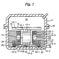
- Fig. 1 shows a general arrangement of a CVD apparatus in which a conventional magnetic floating support apparatus is provided.
- Reference numeral 11 denotes a housing defining a CVD process chamber 10 in which a corrosive process gas is used.
- the housing 11 is formed by connecting a cup-shaped upper half 11-2 and a cup-shaped lower half 11-3 through a seal member 20.
- a turntable 13 on which a semiconductor wafer 12 is mounted is disposed in the housing 11.
- the turntable 13 is supported by a rotary shaft 14.
- a motor rotor 15 is secured to a central portion of the rotary shaft 14.
- Radial magnetic bearing rotors 16-1, 16-2 are secured to the rotary shaft on an upper side and a lower side of the motor rotor 15.
- Radial sensor targets 17-1, 17-2 are secured to the rotary shaft on an upper side of the radial magnetic bearing rotor 16-1 and a lower side of the radial magnetic bearing rotor 16-2.
- an axial magnetic bearing rotor 18 in the form of a circular plate is secured at a lower end of the rotary shaft 14.
- the cylindrical support member 19 includes a central space 19-1 for accommodating the rotary shaft 14 and the elements provided thereon such as the motor rotor 15, and a disk-shaped space 19-2 formed at a lower end of the central space 19-1 so as to accommodate the axial magnetic bearing rotor 18 in the form of a circular plate.
- An annular recess 19-3 is formed in an inner circumferential surface of the cylindrical support member 19 facing the central space 19-1.
- a separation wall 27 made of a non-magnetic material such as stainless steel is provided at an opening of the annular recess 19-3 facing the central space 19-1, so as to seal the annular recess 19-3 from the central space 19-1.
- the axial magnetic bearing stators 24, 25 are accommodated in annular spaces 19-4, 19-5 which are open to the disk-shaped space of the cylindrical support member 19.
- the axial magnetic bearing stators 24, 25 are sealed off from the disk-shaped space 19-2 by means of separation walls 28, 29, which are made of a non-magnetic material such as stainless steel and provided at the openings of the annular spaces.
- separation walls 27, 28, 29, 30 By means of the separation walls 27, 28, 29, 30, the magnetic bearing stators, the displacement sensors and the motor stator in the annular recesses 19-3, 19-4, 19-5 are protected from a corrosive process gas in the CVD process chamber.
- the radial magnetic bearing rotors 16-1, 16-2 and radial magnetic bearing stators 21-1, 21-2 provide radial magnetic bearings, while the axial magnetic bearing rotor 18 and the axial magnetic bearing stators 24, 25 provide an axial magnetic bearing.
- the turntable 13 is magnetically supported in a floating condition by these magnetic bearings.
- the motor stator 22 and the motor rotor 15 form an electric motor which applies a torque to the turntable 13.
- the radial displacement sensors 22-1, 22-2 and an axial displacement sensor 26 detect the positions of the radial sensor targets and the position of an axial sensor target, respectively, and generate position signals, which are supplied to a control circuit (not shown). Based on these signals, the control circuit controls a magnetic attractive force or a magnetic repellent force generated by the radial magnetic bearing stators 21-1, 21-2 and the axial magnetic stator 25 so that the rotary shaft 14 is floated at a predetermined position.
- the present invention has been made. It is an object of the present invention to provide a magnetic bearing in which a magnetic gap between magnetic pole faces of the stator and the rotor can be reduced, and which is reduced in size and has excellent corrosion resistance. It is another object of the present invention to provide a magnetic floating support apparatus using the above-mentioned magnetic bearing.
- the present invention provides a magnetic bearing for effecting floating support of a rotary member having a rotary shaft, comprising: a magnetic bearing rotor provided on the rotary shaft; and a magnetic bearing stator provided around the magnetic bearing rotor, wherein the magnetic bearing stator comprises: a stator core having magnetic pole faces exposed toward the magnetic bearing rotor; excitation coils attached to the stator core; and corrosion-resistant members for shielding the excitation coils from a corrosive atmosphere.
- the corrosion-resistant member can be formed by molding a corrosion-resistant material in a state such that the excitation coil is embedded therein.
- the corrosion-resistant material may be a ceramic or glass type hardenable material.
- the corrosion-resistant member may comprise a case formed from the corrosion-resistant material so that the excitation coil is sealingly enclosed in the case.
- the corrosion-resistant member may comprise a sheath for covering an electrically conductive wire forming the excitation coil.
- the present invention provides a magnetic floating support apparatus comprising a plurality of magnetic bearings and adapted to effect floating support of a rotary member provided in a corrosive atmosphere, wherein each magnetic bearing comprises: a magnetic bearing rotor provided on a rotary shaft; and a magnetic bearing stator provided around the magnetic bearing rotor and the magnetic bearing stator comprises: a stator core having magnetic pole faces exposed toward the magnetic bearing rotor; excitation coils attached to the stator core; and corrosion-resistant members for shielding the excitation coils from the corrosive atmosphere.
- the present invention provides a chemical vapor deposition apparatus comprising a turntable adapted to rotate while a semiconductor wafer is mounted thereon, the chemical vapor deposition apparatus being adapted to conduct a desired process with respect to the semiconductor wafer while the turntable is rotated, the chemical vapor deposition apparatus comprising magnetic bearings for effecting floating support of a rotary shaft of the turntable, wherein each magnetic bearing comprises: a magnetic bearing rotor provided on the rotary shaft; and a magnetic bearing stator provided around the magnetic bearing rotor, and the magnetic bearing stator comprises: a stator core having magnetic pole faces exposed toward the magnetic bearing rotor; excitation coils attached to the stator core; and corrosion-resistant members for shielding the excitation coils from a corrosive atmosphere.
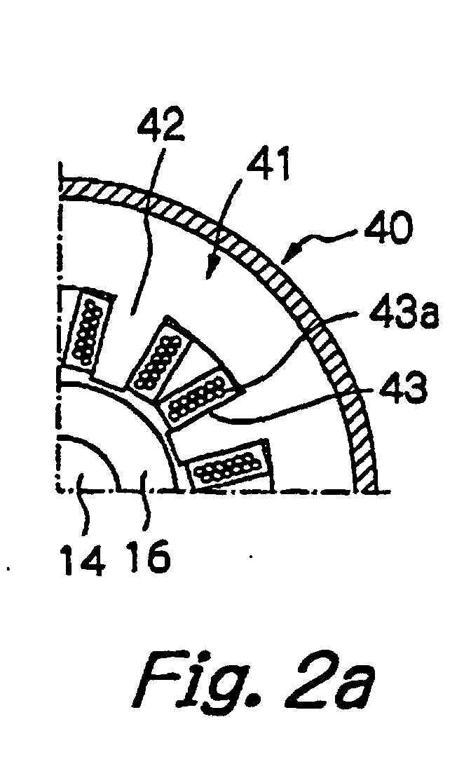
- a stator of a radial magnetic bearing 40 that is, an electromagnet 41, comprises a core (an iron core) 42 made of a magnetic body and excitation coils 43 attached to the core.
- the excitation coil 43 comprises a coil body 43a formed by coiling an electrically conductive wire.
- the coil body is embedded in a corrosion-resistant member 43b formed from a ceramic or glass type hardenable material, which is non-magnetic and has corrosion resistance against a corrosive environment, such as a process gas environment. That is, the ceramic or glass type hardenable material is molded and hardened around the coil body 43a.
- the excitation coil is arranged by molding and hardening the non-magnetic, corrosion-resistant ceramic or glass type hardenable material 43b in a state such that the coil body 43a is embedded therein. Therefore, the excitation coil 43 itself has corrosion resistance. Differing from conventional techniques, it is therefore unnecessary to provide a separation wall on the magnetic pole faces of the stator core 42 facing the magnetic bearing rotor 16, so as to prevent corrosion of the excitation coils 43. That is, the magnetic bearing has a simple structure. Further, because no separation wall is provided, a magnetic gap between the stator magnetic pole 42 and the radial magnetic bearing rotor 16 can be reduced, and the radial magnetic bearing 40 can be reduced in size. Especially, a separation wall provided in a vacuum environment is required to have a large wall thickness Therefore, in a magnetic bearing used in a vacuum environment, elimination of a separation wall results in a substantial reduction in magnetic gap.
- Fig. 3a and Fig. 3b show a transverse section and a vertical section of a radial magnetic bearing according to another embodiment of the present invention.
- the excitation coil 43 is arranged by sealingly enclosing the coil body 43a, which is formed by coiling an electrically conductive wire, in a coil case formed from a corrosion-resistant material, that is, a corrosion-resistant member 43c.
- the excitation coils 43 are attached to the stator core 42, to thereby provide the electromagnet 41 of the radial magnetic bearing 40.
- the excitation coil 43 is arranged by sealingly enclosing the coil body 43a in the coil case 43c having corrosion resistance. Therefore, the excitation coil 43 itself has corrosion resistance. Therefore, differing from conventional techniques, it is unnecessary to provide a separation wall on the magnetic pole faces of the stator core 42 facing the magnetic bearing rotor 16, so as to prevent corrosion of the excitation coils 43.
- Fig. 4a and Fig. 4b show a transverse section and a vertical section of ar radial magnetic bearing according to a further embodiment of the present invention.
- the excitation coil 43 is arranged by coiling a sheath wire 43d which is obtained by covering an electrically conductive wire with a sheath made of an insulating material having corrosion resistance.
- the excitation coils 43 are attached to the stator core 42, to thereby provide the electromagnet 41 of the radial magnetic bearing 40.
- the excitation coil 43 is arranged by coiling the sheath wire 43d having a sheath made of a corrosion-resistant material. Therefore, the excitation coil 43 itself has corrosion resistance. Therefore, there is no need to provide a separation wall such as that mentioned above.
- stator core 42 of the electromagnet 41 of the radial magnetic bearing 40 use is made of a magnetic body having corrosion resistance against a corrosive environment, for example, an austenite type magnetic body or a magnetic body a surface of which has been subjected to an anticorrosion treatment, such as nickel plating.
- the same effect as described above can be obtained by embedding a coil body in a corrosion-resistant member obtained by molding and hardening a non-magnetic, corrosion-resistant ceramic or glass type hardenable material, sealingly enclosing a coil body in a corrosion-resistant coil case or sealingly covering an electrically conductive wire with a sheath made of a corrosion-resistant material, although these arrangements are not shown with respect to the electromagnet of the axial magnetic bearing.
- a coil having a corrosion-resistant structure such as that mentioned above is employed as the coil of the sensor, so that there is no need to provide a separation wall on the surface of the sensor magnetic pole facing the sensor target. Therefore, the magnetic gap can be reduced and a small sensor having high sensitivity can be obtained.
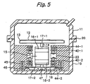
- Figs. 5 to 7 show a general arrangement of a CVD apparatus in which a magnetic floating support apparatus using a magnetic bearing of the present invention is provided.
- Fig. 5 shows an arrangement of the entire magnetic floating support apparatus.
- Fig. 6 shows arrangements of a radial magnetic bearing portion and a motor portion.
- Fig. 7 is a cross-sectional view, taken along the line A-A in Fig. 6.
- the portions which are the same or correspond to those shown in Figs. 1 to 4 are designated by the same reference numerals as used in Figs. 1 to 4.
- the motor stator 23 is provided around the motor rotor 15
- radial magnetic bearing stators (electromagnets) 40-1, 40-2 are provided around the radial magnetic bearing rotors 16-1, 16-2
- radial position sensors 44-1, 44-2 are provided around the radial sensor targets 17-1, 17-2.
- Axial magnetic bearing stators (electromagnets) 45, 46 are provided in the vicinity of an outer peripheral portion of the axial magnetic bearing rotor 18 so as to face an upper surface and a lower surface thereof.
- An axial displacement sensor 47 is provided so as to face a lower surface of a central portion of the axial magnetic bearing rotor 18.
- the excitation coil 43 (see Fig. 2) is obtained as one unit by embedding the coil body 43a, which is formed by coiling an electrically conductive wire, in a corrosion-resistant member formed by molding and hardening the ceramic or glass type hardenable material 43b, which is non-magnetic and has corrosion resistance against a corrosive environment such as a process gas environment.
- the coil body in the electromagnets of the axial magnetic bearings 45, 46, the coil body can be embedded in a corrosion-resistant member formed by molding a ceramic or glass type hardenable material which is non-magnetic and has corrosion resistance, can be sealingly enclosed in a coil case having corrosion resistance, or can be formed by sealingly covering an electrically conductive wire with a sheath made of a corrosion-resistant material.
- the magnetic floating support apparatus can be reduced in size.
- a conventional magnetic floating support apparatus provided in the CVD process chamber 10 in which a vacuum is normally created, it is required to provide a separation wall having a large wall thickness so as to obtain a sufficiently large strength of the wall.
- such a separation wall is not required to be used, so that the magnetic gap can be reduced by a distance corresponding to the large wall thickness of the separation wall. This markedly reduces the size of the magnetic floating support apparatus.
- the coil of the sensor is protected by a corrosion-resistant member such as that mentioned above, so that it is unnecessary to provide a separation wall between the sensor and the sensor target, and therefore a displacement sensor having high sensitivity can be obtained.
- the motor stator 23 is also imparted with a corrosion-resistant structure.
- the coil of the motor stator be imparted with a corrosion-resistant structure and the iron core of the stator be imparted with a corrosion-resistant structure or subjected to an anticorrosion treatment.
- a can structure may be formed, in which the portion of the motor stator 23 exposed to a corrosive environment is covered with a separation wall (a can).
- a magnetic bearing and a magnetic floating support apparatus according to the present invention can be effectively utilized especially in a corrosive gas environment, for example, in a CVD apparatus for processing of semiconductor wafers.
Landscapes
- Engineering & Computer Science (AREA)
- General Engineering & Computer Science (AREA)
- Mechanical Engineering (AREA)
- Physics & Mathematics (AREA)
- Electromagnetism (AREA)
- Magnetic Bearings And Hydrostatic Bearings (AREA)
- Chemical Vapour Deposition (AREA)
Abstract
There is provided a magnetic bearing in which a
magnetic gap between magnetic pole faces of the stator and
the rotor can be reduced, and which is reduced in size and
has excellent corrosion resistance. This magnetic bearing
comprises: a magnetic bearing rotor 16 provided on the
rotary shaft; and a magnetic bearing stator 41 provided
around the magnetic bearing rotor, wherein the magnetic
bearing stator comprises: a stator core 42 having magnetic
pole faces exposed toward the magnetic bearing rotor;
excitation coils 43a attached to the stator core; and
corrosion-resistant members 43 for shielding the excitation
coils 43a from a corrosive atmosphere. The corrosion-resistant
member can be formed by molding a ceramic or
glass type hardenable material in a state such that the
excitation coil 43a is embedded therein. The corrosion-resistant
member may comprise a case 43c formed from the
corrosion-resistant material. The corrosion-resistant
member may comprise a sheath for covering an electrically
conductive wire forming the excitation coil.
Description
- The present invention relates to a magnetic bearing which is suitably used in a corrosive environment, especially in a highly corrosive gas environment. The present invention also relates to a magnetic floating support apparatus using such a magnetic bearing.
- In a chemical vapor deposition (CVD) apparatus used for manufacture of semiconductors, a highly corrosive process gas is used. Therefore, a mount on which a substrate to be processed is mounted and magnetic bearings for effecting floating support of the mount are exposed to a highly corrosive process gas in a chamber of the apparatus. Therefore, various measures are taken so as to prevent corrosion of the mount and the magnetic bearings due to the process gas.
- Fig. 1 shows a general arrangement of a CVD apparatus in which a conventional magnetic floating support apparatus is provided.
Reference numeral 11 denotes a housing defining aCVD process chamber 10 in which a corrosive process gas is used. Thehousing 11 is formed by connecting a cup-shaped upper half 11-2 and a cup-shaped lower half 11-3 through aseal member 20. Aturntable 13 on which asemiconductor wafer 12 is mounted is disposed in thehousing 11. - The
turntable 13 is supported by arotary shaft 14. Amotor rotor 15 is secured to a central portion of therotary shaft 14. Radial magnetic bearing rotors 16-1, 16-2 are secured to the rotary shaft on an upper side and a lower side of themotor rotor 15. Radial sensor targets 17-1, 17-2 are secured to the rotary shaft on an upper side of the radial magnetic bearing rotor 16-1 and a lower side of the radial magnetic bearing rotor 16-2. Further, an axial magnetic bearingrotor 18 in the form of a circular plate is secured at a lower end of therotary shaft 14. A motor stator (an electromagnet) 23, radial magnetic bearing stators (electromagnets) 21-1, 21-2 and radial displacement sensors 22-1, 22-2, which are associated with themotor rotor 15, the radial magnetic bearing rotors 16-1, 16-2 and the radial sensor targets 17-1, 17-2, are securely provided around therotary shaft 14. Further, axial magnetic bearing stators (electromagnets) 24, 25 are disposed on an upper side and a lower side of a peripheral portion of the axial magnetic bearingrotor 18 in the form of a circular plate. The axialmagnetic bearing stators cylindrical support member 19 disposed in the lower half in thehousing 10. - Illustratively stated, the
cylindrical support member 19 includes a central space 19-1 for accommodating therotary shaft 14 and the elements provided thereon such as themotor rotor 15, and a disk-shaped space 19-2 formed at a lower end of the central space 19-1 so as to accommodate the axial magnetic bearingrotor 18 in the form of a circular plate. An annular recess 19-3 is formed in an inner circumferential surface of thecylindrical support member 19 facing the central space 19-1. Aseparation wall 27 made of a non-magnetic material such as stainless steel is provided at an opening of the annular recess 19-3 facing the central space 19-1, so as to seal the annular recess 19-3 from the central space 19-1. The axial magnetic bearingstators cylindrical support member 19. The axial magnetic bearingstators separation walls separation walls - The radial magnetic bearing rotors 16-1, 16-2 and radial magnetic bearing stators 21-1, 21-2 provide radial magnetic bearings, while the axial magnetic bearing
rotor 18 and the axial magnetic bearingstators turntable 13 is magnetically supported in a floating condition by these magnetic bearings. The motor stator 22 and themotor rotor 15 form an electric motor which applies a torque to theturntable 13. - The radial displacement sensors 22-1, 22-2 and an
axial displacement sensor 26 detect the positions of the radial sensor targets and the position of an axial sensor target, respectively, and generate position signals, which are supplied to a control circuit (not shown). Based on these signals, the control circuit controls a magnetic attractive force or a magnetic repellent force generated by the radial magnetic bearing stators 21-1, 21-2 and the axialmagnetic stator 25 so that therotary shaft 14 is floated at a predetermined position. - When the
separation walls stators magnetic bearing stators rotor 18 are increased. - When the magnetic gap is increased, a magnetic force required for controlling magnetic floating support of the rotary shaft is markedly decreased. Therefore, in order to obtain a desired magnetic force for controlling magnetic floating support of the rotary shaft, the ampere-turn of an excitation coil of the magnetic bearing stator must be increased. This is undesirable because the magnetic bearing inevitably becomes large. Especially in a CVD apparatus, a vacuum is created in the
CVD process chamber 10 by means of a vacuum pump, and the magnetic bearing is used under vacuum conditions. This requires that theseparation walls - In view of the above, the present invention has been made. It is an object of the present invention to provide a magnetic bearing in which a magnetic gap between magnetic pole faces of the stator and the rotor can be reduced, and which is reduced in size and has excellent corrosion resistance. It is another object of the present invention to provide a magnetic floating support apparatus using the above-mentioned magnetic bearing.
- That is, the present invention provides a magnetic bearing for effecting floating support of a rotary member having a rotary shaft, comprising: a magnetic bearing rotor provided on the rotary shaft; and a magnetic bearing stator provided around the magnetic bearing rotor, wherein the magnetic bearing stator comprises: a stator core having magnetic pole faces exposed toward the magnetic bearing rotor; excitation coils attached to the stator core; and corrosion-resistant members for shielding the excitation coils from a corrosive atmosphere.
- The corrosion-resistant member can be formed by molding a corrosion-resistant material in a state such that the excitation coil is embedded therein. The corrosion-resistant material may be a ceramic or glass type hardenable material. The corrosion-resistant member may comprise a case formed from the corrosion-resistant material so that the excitation coil is sealingly enclosed in the case. The corrosion-resistant member may comprise a sheath for covering an electrically conductive wire forming the excitation coil.
- Further, the present invention provides a magnetic floating support apparatus comprising a plurality of magnetic bearings and adapted to effect floating support of a rotary member provided in a corrosive atmosphere, wherein each magnetic bearing comprises: a magnetic bearing rotor provided on a rotary shaft; and a magnetic bearing stator provided around the magnetic bearing rotor and the magnetic bearing stator comprises: a stator core having magnetic pole faces exposed toward the magnetic bearing rotor; excitation coils attached to the stator core; and corrosion-resistant members for shielding the excitation coils from the corrosive atmosphere.
- In this case, various forms of corrosion-resistant members may be employed, as in the case of the above-mentioned magnetic bearing.
- Further, the present invention provides a chemical vapor deposition apparatus comprising a turntable adapted to rotate while a semiconductor wafer is mounted thereon, the chemical vapor deposition apparatus being adapted to conduct a desired process with respect to the semiconductor wafer while the turntable is rotated, the chemical vapor deposition apparatus comprising magnetic bearings for effecting floating support of a rotary shaft of the turntable, wherein each magnetic bearing comprises: a magnetic bearing rotor provided on the rotary shaft; and a magnetic bearing stator provided around the magnetic bearing rotor, and the magnetic bearing stator comprises: a stator core having magnetic pole faces exposed toward the magnetic bearing rotor; excitation coils attached to the stator core; and corrosion-resistant members for shielding the excitation coils from a corrosive atmosphere.
- In this chemical vapor deposition apparatus, various forms of corrosion-resistant members may be employed, as in the case of the above-mentioned magnetic bearing.
-
- Fig. 1 shows a general arrangement of a CVD apparatus in which a conventional magnetic floating support apparatus is provided.
- Fig. 2a shows a transverse section of a radial magnetic bearing according to an embodiment of the present invention.
- Fig. 2b shows a vertical section of the radial magnetic bearing.
- Fig. 3a shows a transverse section of a radial magnetic bearing according to another embodiment of the present invention.
- Fig. 3b shows a vertical section of the radial magnetic bearing.
- Fig. 4a shows a transverse section of a radial magnetic bearing according to a further embodiment of the present invention.
- Fig. 4b shows a vertical section of the radial magnetic bearing.
- Fig. 5 shows a general arrangement of a CVD apparatus in which a magnetic floating support apparatus according to the present invention is provided.
- Fig. 6 shows arrangements of a magnetic bearing portion and a motor portion of the apparatus shown in Fig. 5.
- Fig. 7 is a cross-sectional view, taken along the line A-A in Fig. 6.
-
- Hereinbelow, embodiments of the present invention are described, with reference to the drawings.
- Fig. 2a and Fig. 2b show a transverse section and a vertical section of a part of a radial magnetic bearing according to the present invention. As shown in the drawings, a stator of a radial
magnetic bearing 40, that is, anelectromagnet 41, comprises a core (an iron core) 42 made of a magnetic body and excitation coils 43 attached to the core. Theexcitation coil 43 comprises acoil body 43a formed by coiling an electrically conductive wire. The coil body is embedded in a corrosion-resistant member 43b formed from a ceramic or glass type hardenable material, which is non-magnetic and has corrosion resistance against a corrosive environment, such as a process gas environment. That is, the ceramic or glass type hardenable material is molded and hardened around thecoil body 43a. - Thus, the excitation coil is arranged by molding and hardening the non-magnetic, corrosion-resistant ceramic or glass
type hardenable material 43b in a state such that thecoil body 43a is embedded therein. Therefore, theexcitation coil 43 itself has corrosion resistance. Differing from conventional techniques, it is therefore unnecessary to provide a separation wall on the magnetic pole faces of thestator core 42 facing themagnetic bearing rotor 16, so as to prevent corrosion of the excitation coils 43. That is, the magnetic bearing has a simple structure. Further, because no separation wall is provided, a magnetic gap between the statormagnetic pole 42 and the radialmagnetic bearing rotor 16 can be reduced, and the radialmagnetic bearing 40 can be reduced in size. Especially, a separation wall provided in a vacuum environment is required to have a large wall thickness Therefore, in a magnetic bearing used in a vacuum environment, elimination of a separation wall results in a substantial reduction in magnetic gap. - Fig. 3a and Fig. 3b show a transverse section and a vertical section of a radial magnetic bearing according to another embodiment of the present invention. As shown in the drawings, the
excitation coil 43 is arranged by sealingly enclosing thecoil body 43a, which is formed by coiling an electrically conductive wire, in a coil case formed from a corrosion-resistant material, that is, a corrosion-resistant member 43c. The excitation coils 43 are attached to thestator core 42, to thereby provide theelectromagnet 41 of the radialmagnetic bearing 40. - Thus, the
excitation coil 43 is arranged by sealingly enclosing thecoil body 43a in the coil case 43c having corrosion resistance. Therefore, theexcitation coil 43 itself has corrosion resistance. Therefore, differing from conventional techniques, it is unnecessary to provide a separation wall on the magnetic pole faces of thestator core 42 facing themagnetic bearing rotor 16, so as to prevent corrosion of the excitation coils 43. - Fig. 4a and Fig. 4b show a transverse section and a vertical section of ar radial magnetic bearing according to a further embodiment of the present invention. As shown in the drawings, the
excitation coil 43 is arranged by coiling a sheath wire 43d which is obtained by covering an electrically conductive wire with a sheath made of an insulating material having corrosion resistance. The excitation coils 43 are attached to thestator core 42, to thereby provide theelectromagnet 41 of the radialmagnetic bearing 40. - Thus, the
excitation coil 43 is arranged by coiling the sheath wire 43d having a sheath made of a corrosion-resistant material. Therefore, theexcitation coil 43 itself has corrosion resistance. Therefore, there is no need to provide a separation wall such as that mentioned above. - As a material for the
stator core 42 of theelectromagnet 41 of the radialmagnetic bearing 40, use is made of a magnetic body having corrosion resistance against a corrosive environment, for example, an austenite type magnetic body or a magnetic body a surface of which has been subjected to an anticorrosion treatment, such as nickel plating. - With respect to the electromagnet of the axial magnetic bearing, the same effect as described above can be obtained by embedding a coil body in a corrosion-resistant member obtained by molding and hardening a non-magnetic, corrosion-resistant ceramic or glass type hardenable material, sealingly enclosing a coil body in a corrosion-resistant coil case or sealingly covering an electrically conductive wire with a sheath made of a corrosion-resistant material, although these arrangements are not shown with respect to the electromagnet of the axial magnetic bearing.
- When an inductance type sensor is used as the radial displacement sensor, a coil having a corrosion-resistant structure such as that mentioned above is employed as the coil of the sensor, so that there is no need to provide a separation wall on the surface of the sensor magnetic pole facing the sensor target. Therefore, the magnetic gap can be reduced and a small sensor having high sensitivity can be obtained.
- Figs. 5 to 7 show a general arrangement of a CVD apparatus in which a magnetic floating support apparatus using a magnetic bearing of the present invention is provided. Fig. 5 shows an arrangement of the entire magnetic floating support apparatus. Fig. 6 shows arrangements of a radial magnetic bearing portion and a motor portion. Fig. 7 is a cross-sectional view, taken along the line A-A in Fig. 6. In Figs. 5 to 7, the portions which are the same or correspond to those shown in Figs. 1 to 4 are designated by the same reference numerals as used in Figs. 1 to 4.
- As shown in these drawings, the
motor stator 23 is provided around themotor rotor 15, radial magnetic bearing stators (electromagnets) 40-1, 40-2 are provided around the radial magnetic bearing rotors 16-1, 16-2, and radial position sensors 44-1, 44-2 are provided around the radial sensor targets 17-1, 17-2. Axial magnetic bearing stators (electromagnets) 45, 46 are provided in the vicinity of an outer peripheral portion of the axialmagnetic bearing rotor 18 so as to face an upper surface and a lower surface thereof. Anaxial displacement sensor 47 is provided so as to face a lower surface of a central portion of the axialmagnetic bearing rotor 18. - In this CVD apparatus, as the radial magnetic bearing stators 40-1, 40-2, either of the radial
magnetic bearings 40 having arrangements shown in Figs. 2 to 4 is used. In this embodiment, the excitation coil 43 (see Fig. 2) is obtained as one unit by embedding thecoil body 43a, which is formed by coiling an electrically conductive wire, in a corrosion-resistant member formed by molding and hardening the ceramic or glasstype hardenable material 43b, which is non-magnetic and has corrosion resistance against a corrosive environment such as a process gas environment. - Further, as the axial
magnetic bearings magnetic bearings - Thus, according to the present invention, differing from conventional techniques, it is unnecessary to shield the rotor-facing surface of the magnetic bearing stator from a corrosive environment, by means of a non-magnetic separation wall. Therefore, the magnetic gap between the stator and the rotor can be reduced and a force required for effecting floating support can be obtained with a low power consumption. Therefore, the magnetic floating support apparatus can be reduced in size. Especially, in a conventional magnetic floating support apparatus provided in the
CVD process chamber 10 in which a vacuum is normally created, it is required to provide a separation wall having a large wall thickness so as to obtain a sufficiently large strength of the wall. In the present invention, such a separation wall is not required to be used, so that the magnetic gap can be reduced by a distance corresponding to the large wall thickness of the separation wall. This markedly reduces the size of the magnetic floating support apparatus. - When an inductance type sensor is used as the radial displacement sensors 44-1, 44-2 and the
axial displacement sensor 47, the coil of the sensor is protected by a corrosion-resistant member such as that mentioned above, so that it is unnecessary to provide a separation wall between the sensor and the sensor target, and therefore a displacement sensor having high sensitivity can be obtained. - Further, the
motor stator 23 is also imparted with a corrosion-resistant structure. For example, it is preferred that the coil of the motor stator be imparted with a corrosion-resistant structure and the iron core of the stator be imparted with a corrosion-resistant structure or subjected to an anticorrosion treatment. Alternatively, a can structure may be formed, in which the portion of themotor stator 23 exposed to a corrosive environment is covered with a separation wall (a can). - A magnetic bearing and a magnetic floating support apparatus according to the present invention can be effectively utilized especially in a corrosive gas environment, for example, in a CVD apparatus for processing of semiconductor wafers.
Claims (15)
- A magnetic bearing for effecting floating support of a rotary member having a rotary shaft, comprising:wherein the magnetic bearing stator comprises:a magnetic bearing rotor provided on the rotary shaft; anda magnetic bearing stator provided around the magnetic bearing rotor,a stator core having magnetic pole faces exposed toward the magnetic bearing rotor;excitation coils attached to the stator core; andcorrosion-resistant members for shielding the excitation coils from a corrosive atmosphere.
- The magnetic bearing according to claim 1, wherein the corrosion-resistant member is formed by molding a corrosion-resistant material in a state such that the excitation coil is embedded therein.
- The magnetic bearing according to claim 2, wherein the corrosion-resistant material is a ceramic or glass type hardenable material.
- The magnetic bearing according to claim 1. wherein the corrosion-resistant member comprises a case formed from a corrosion-resistant material, the excitation coil being sealingly enclosed in the case.
- The magnetic bearing according to claim 1, wherein the corrosion-resistant member comprises a sheath for covering an electrically conductive wire forming the excitation coil.
- A magnetic floating support apparatus comprising a plurality of magnetic bearings and adapted to effect floating support of a rotary member provided in a corrosive atmosphere,
wherein each magnetic bearing comprises:a magnetic bearing rotor provided on a rotary shaft; anda magnetic bearing stator provided around the magnetic bearing rotor, andthe magnetic bearing stator comprises:a stator core having magnetic pole faces exposed toward the magnetic bearing rotor;excitation coils attached to the stator core; andcorrosion-resistant members for shielding the excitation coils from the corrosive atmosphere. - The magnetic floating support apparatus according to claim 6, wherein the corrosion-resistant member is formed by molding a corrosion-resistant material in a state such that the excitation coil is embedded therein.
- The magnetic floating support apparatus according to claim 7, wherein the corrosion-resistant material is a ceramic or glass type hardenable material.
- The magnetic floating support apparatus according to claim 6, wherein the corrosion-resistant member comprises a case formed from a corrosion-resistant material, the excitation coil being sealingly enclosed in the case.
- The magnetic floating support apparatus according to claim 6, wherein the corrosion-resistant member comprises a sheath for covering an electrically conductive wire forming the excitation coil.
- A chemical vapor deposition apparatus comprising a turntable adapted to rotate while a semiconductor wafer is mounted thereon, the chemical vapor deposition apparatus being adapted to conduct a desired process with respect to the semiconductor wafer while the turntable is rotated, the chemical vapor deposition apparatus comprising magnetic bearings for effecting floating support of a rotary shaft of the turntable,
wherein each magnetic bearing comprises:a magnetic bearing rotor provided on the rotary shaft: anda magnetic bearing stator provided around the magnetic bearing rotor, andthe magnetic bearing stator comprises:a stator core having magnetic pole faces exposed toward the magnetic bearing rotor;excitation coils attached to the stator core; andcorrosion-resistant members for shielding the excitation coils from a corrosive atmosphere. - The chemical vapor deposition apparatus according to claim 11, wherein the corrosion-resistant member is formed by molding a corrosion-resistant material in a state such that the excitation coil is embedded therein.
- The chemical vapor deposition apparatus according to claim 12, wherein the corrosion-resistant material is a ceramic or glass type hardenable material.
- The chemical vapor deposition apparatus according to claim 11, wherein the corrosion-resistant member comprises a case formed from a corrosion-resistant material, the excitation coil being sealingly enclosed in the case.
- The chemical vapor deposition apparatus according to claim 11, wherein the corrosion-resistant member comprises a sheath for covering an electrically conductive wire forming the excitation coil.
Applications Claiming Priority (3)
| Application Number | Priority Date | Filing Date | Title |
|---|---|---|---|
| JP2000126118A JP2001304258A (en) | 2000-04-26 | 2000-04-26 | Magnetic bearing and magnetic levitation device |
| JP2000126118 | 2000-04-26 | ||
| PCT/JP2001/003651 WO2001081780A1 (en) | 2000-04-26 | 2001-04-26 | Magnetic bearing and magnetic levitation apparatus |
Publications (1)
| Publication Number | Publication Date |
|---|---|
| EP1288511A1 true EP1288511A1 (en) | 2003-03-05 |
Family
ID=18635957
Family Applications (1)
| Application Number | Title | Priority Date | Filing Date |
|---|---|---|---|
| EP01925982A Withdrawn EP1288511A1 (en) | 2000-04-26 | 2001-04-26 | Magnetic bearing and magnetic levitation apparatus |
Country Status (6)
| Country | Link |
|---|---|
| US (1) | US20030107282A1 (en) |
| EP (1) | EP1288511A1 (en) |
| JP (1) | JP2001304258A (en) |
| KR (1) | KR20030042439A (en) |
| TW (1) | TW555940B (en) |
| WO (1) | WO2001081780A1 (en) |
Cited By (3)
| Publication number | Priority date | Publication date | Assignee | Title |
|---|---|---|---|---|
| GB2387204A (en) * | 2002-03-14 | 2003-10-08 | Edward Camplin | Magnetic rotary suspension bearing |
| US7663281B1 (en) | 2004-08-31 | 2010-02-16 | Jeffrey J Nau | Magnetic field generating device |
| EP2372749A1 (en) * | 2010-03-31 | 2011-10-05 | Levitronix GmbH | Treatment device for treating a surface of a body |
Families Citing this family (15)
| Publication number | Priority date | Publication date | Assignee | Title |
|---|---|---|---|---|
| US7217325B2 (en) * | 1999-01-22 | 2007-05-15 | Semitool, Inc. | System for processing a workpiece |
| JP3711277B2 (en) * | 2002-12-17 | 2005-11-02 | 核燃料サイクル開発機構 | Centrifugal extractor with non-contact shaft structure |
| TW200525086A (en) * | 2003-10-21 | 2005-08-01 | Nabtesco Corp | Rotary dry vacuum pump |
| EP2188541B1 (en) * | 2007-08-14 | 2012-04-18 | Rothe Erde GmbH | Method and bearing for supporting rotatable devices, particularly a medical scanner |
| US8513826B2 (en) * | 2008-06-26 | 2013-08-20 | Ed Mazur | Wind turbine |
| US8850989B2 (en) * | 2010-12-03 | 2014-10-07 | Sandor Wayne Shapery | Magnetic levitation assembly |
| CN105940481A (en) * | 2014-01-27 | 2016-09-14 | 应用材料公司 | High Speed EPI System and Chamber Concept |
| WO2016181919A1 (en) * | 2015-05-11 | 2016-11-17 | 株式会社荏原製作所 | Electromagnet device, electromagnet control device, electromagnet control method, and electromagnet system |
| CN106337876B (en) * | 2016-10-13 | 2018-10-16 | 中国人民解放军海军工程大学 | Heteropolar formula permanent magnetic offset mixed radial magnetic bearing |
| WO2019026673A1 (en) * | 2017-08-01 | 2019-02-07 | 三菱電機株式会社 | Rotation drive device, method for mounting rotation drive device, axial flow blower, method for mounting axial flow blower, and lasing device |
| CN108443335B (en) * | 2018-05-30 | 2024-04-05 | 江苏理工学院 | Crank sliding block type radial protection bearing |
| JP7055720B2 (en) | 2018-08-10 | 2022-04-18 | 株式会社荏原製作所 | Control method for board rotating device, board cleaning device, board processing device, and board rotating device |
| CN113745138B (en) * | 2021-09-03 | 2024-03-22 | 上海隐冠半导体技术有限公司 | Magnetic levitation device and micro-motion platform |
| JP7745509B2 (en) * | 2022-05-30 | 2025-09-29 | 株式会社荏原製作所 | magnetic bearing device |
| CN116002025B (en) * | 2022-09-09 | 2025-04-04 | 哈尔滨工程大学 | A full-sea-depth oil-filled corrosion-resistant electromagnetic chuck device |
Family Cites Families (5)
| Publication number | Priority date | Publication date | Assignee | Title |
|---|---|---|---|---|
| JPH06150722A (en) * | 1992-11-05 | 1994-05-31 | Furukawa Electric Co Ltd:The | Conductor for coil |
| JPH06232047A (en) * | 1993-01-29 | 1994-08-19 | Mitsubishi Heavy Ind Ltd | Wafer rotation device |
| JP3315027B2 (en) * | 1995-11-14 | 2002-08-19 | 株式会社荏原製作所 | Magnetic bearing for high pressure liquid |
| JP3696398B2 (en) * | 1997-04-28 | 2005-09-14 | Ntn株式会社 | Hydrostatic magnetic compound bearing and spindle device |
| JP3930170B2 (en) * | 1998-02-18 | 2007-06-13 | 株式会社荏原製作所 | Circulation fan device |
-
2000
- 2000-04-26 JP JP2000126118A patent/JP2001304258A/en active Pending
-
2001
- 2001-04-26 US US10/258,536 patent/US20030107282A1/en not_active Abandoned
- 2001-04-26 EP EP01925982A patent/EP1288511A1/en not_active Withdrawn
- 2001-04-26 WO PCT/JP2001/003651 patent/WO2001081780A1/en not_active Ceased
- 2001-04-26 KR KR1020027014352A patent/KR20030042439A/en not_active Withdrawn
- 2001-04-26 TW TW090109973A patent/TW555940B/en active
Non-Patent Citations (1)
| Title |
|---|
| See references of WO0181780A1 * |
Cited By (5)
| Publication number | Priority date | Publication date | Assignee | Title |
|---|---|---|---|---|
| GB2387204A (en) * | 2002-03-14 | 2003-10-08 | Edward Camplin | Magnetic rotary suspension bearing |
| GB2387204B (en) * | 2002-03-14 | 2006-01-18 | Edward Camplin | Magnetic rotary suspension bearing |
| US7663281B1 (en) | 2004-08-31 | 2010-02-16 | Jeffrey J Nau | Magnetic field generating device |
| EP2372749A1 (en) * | 2010-03-31 | 2011-10-05 | Levitronix GmbH | Treatment device for treating a surface of a body |
| US10468277B2 (en) | 2010-03-31 | 2019-11-05 | Levitronix Gmbh | Treatment apparatus for treating a surface of a body |
Also Published As
| Publication number | Publication date |
|---|---|
| US20030107282A1 (en) | 2003-06-12 |
| WO2001081780A1 (en) | 2001-11-01 |
| KR20030042439A (en) | 2003-05-28 |
| TW555940B (en) | 2003-10-01 |
| JP2001304258A (en) | 2001-10-31 |
Similar Documents
| Publication | Publication Date | Title |
|---|---|---|
| US20030107282A1 (en) | Magnetic bearing and magnetic levitation apparatus | |
| CN103422067B (en) | There is the life-span of raising and the sputtering target material of sputtering uniformity | |
| RU1831589C (en) | Vacuum pump for pure molecular vacuum | |
| KR100726016B1 (en) | Substrate rotator | |
| EP0735633A2 (en) | Means for establishing electrical contact between a rotatable electrical conductor and grounded means | |
| US10819168B2 (en) | Electric motor | |
| US6991439B2 (en) | Vacuum pump | |
| US6559568B2 (en) | Magnetic bearing type vacuum pump | |
| JP7600711B2 (en) | Motor | |
| EP1128079B1 (en) | Magnetic bearing and circulation fan apparatus | |
| KR102539527B1 (en) | Vacuum pump, magnetic bearing part and shaft provided in the vacuum pump | |
| KR20230062812A (en) | vacuum pump | |
| CN101463825A (en) | Vacuum pump | |
| US20020094600A1 (en) | Substrate processing apparatus and method for manufacturing a semiconductor device employing same | |
| US6809448B2 (en) | Excimer laser apparatus | |
| JP5288164B2 (en) | Scalar robot | |
| JP2025138333A (en) | vacuum pump | |
| US20060034713A1 (en) | Turbo pump and processing apparatus comprising the same | |
| JP5401837B2 (en) | Direct drive motor, transfer robot, and semiconductor manufacturing equipment | |
| JPH03150041A (en) | Enclosed actuator | |
| JP4736025B2 (en) | Direct drive motor | |
| US20250286432A1 (en) | Magnetic levitation device and an electromagnetic rotary drive | |
| JP2003283010A (en) | Gas laser apparatus | |
| JP4613573B2 (en) | Motor system | |
| TW202549227A (en) | A magnetic levitation device and an electromagnetic rotary drive |
Legal Events
| Date | Code | Title | Description |
|---|---|---|---|
| PUAI | Public reference made under article 153(3) epc to a published international application that has entered the european phase |
Free format text: ORIGINAL CODE: 0009012 |
|
| 17P | Request for examination filed |
Effective date: 20021025 |
|
| AK | Designated contracting states |
Kind code of ref document: A1 Designated state(s): DE FR GB NL Designated state(s): DE FR GB NL |
|
| RBV | Designated contracting states (corrected) |
Designated state(s): DE FR |
|
| STAA | Information on the status of an ep patent application or granted ep patent |
Free format text: STATUS: THE APPLICATION IS DEEMED TO BE WITHDRAWN |
|
| 18D | Application deemed to be withdrawn |
Effective date: 20041101 |