EP1288050A1 - Motor structure of an electric vehicle - Google Patents
Motor structure of an electric vehicle Download PDFInfo
- Publication number
- EP1288050A1 EP1288050A1 EP02017937A EP02017937A EP1288050A1 EP 1288050 A1 EP1288050 A1 EP 1288050A1 EP 02017937 A EP02017937 A EP 02017937A EP 02017937 A EP02017937 A EP 02017937A EP 1288050 A1 EP1288050 A1 EP 1288050A1
- Authority
- EP
- European Patent Office
- Prior art keywords
- electric motor
- electric
- electric vehicle
- fuel cell
- radiator
- Prior art date
- Legal status (The legal status is an assumption and is not a legal conclusion. Google has not performed a legal analysis and makes no representation as to the accuracy of the status listed.)
- Granted
Links
Images


Classifications
-
- B—PERFORMING OPERATIONS; TRANSPORTING
- B60—VEHICLES IN GENERAL
- B60K—ARRANGEMENT OR MOUNTING OF PROPULSION UNITS OR OF TRANSMISSIONS IN VEHICLES; ARRANGEMENT OR MOUNTING OF PLURAL DIVERSE PRIME-MOVERS IN VEHICLES; AUXILIARY DRIVES FOR VEHICLES; INSTRUMENTATION OR DASHBOARDS FOR VEHICLES; ARRANGEMENTS IN CONNECTION WITH COOLING, AIR INTAKE, GAS EXHAUST OR FUEL SUPPLY OF PROPULSION UNITS IN VEHICLES
- B60K17/00—Arrangement or mounting of transmissions in vehicles
- B60K17/04—Arrangement or mounting of transmissions in vehicles characterised by arrangement, location or kind of gearing
- B60K17/16—Arrangement or mounting of transmissions in vehicles characterised by arrangement, location or kind of gearing of differential gearing
-
- B—PERFORMING OPERATIONS; TRANSPORTING
- B60—VEHICLES IN GENERAL
- B60K—ARRANGEMENT OR MOUNTING OF PROPULSION UNITS OR OF TRANSMISSIONS IN VEHICLES; ARRANGEMENT OR MOUNTING OF PLURAL DIVERSE PRIME-MOVERS IN VEHICLES; AUXILIARY DRIVES FOR VEHICLES; INSTRUMENTATION OR DASHBOARDS FOR VEHICLES; ARRANGEMENTS IN CONNECTION WITH COOLING, AIR INTAKE, GAS EXHAUST OR FUEL SUPPLY OF PROPULSION UNITS IN VEHICLES
- B60K1/00—Arrangement or mounting of electrical propulsion units
-
- B—PERFORMING OPERATIONS; TRANSPORTING
- B60—VEHICLES IN GENERAL
- B60K—ARRANGEMENT OR MOUNTING OF PROPULSION UNITS OR OF TRANSMISSIONS IN VEHICLES; ARRANGEMENT OR MOUNTING OF PLURAL DIVERSE PRIME-MOVERS IN VEHICLES; AUXILIARY DRIVES FOR VEHICLES; INSTRUMENTATION OR DASHBOARDS FOR VEHICLES; ARRANGEMENTS IN CONNECTION WITH COOLING, AIR INTAKE, GAS EXHAUST OR FUEL SUPPLY OF PROPULSION UNITS IN VEHICLES
- B60K11/00—Arrangement in connection with cooling of propulsion units
- B60K11/02—Arrangement in connection with cooling of propulsion units with liquid cooling
- B60K11/04—Arrangement or mounting of radiators, radiator shutters, or radiator blinds
-
- B—PERFORMING OPERATIONS; TRANSPORTING
- B60—VEHICLES IN GENERAL
- B60K—ARRANGEMENT OR MOUNTING OF PROPULSION UNITS OR OF TRANSMISSIONS IN VEHICLES; ARRANGEMENT OR MOUNTING OF PLURAL DIVERSE PRIME-MOVERS IN VEHICLES; AUXILIARY DRIVES FOR VEHICLES; INSTRUMENTATION OR DASHBOARDS FOR VEHICLES; ARRANGEMENTS IN CONNECTION WITH COOLING, AIR INTAKE, GAS EXHAUST OR FUEL SUPPLY OF PROPULSION UNITS IN VEHICLES
- B60K17/00—Arrangement or mounting of transmissions in vehicles
- B60K17/22—Arrangement or mounting of transmissions in vehicles characterised by arrangement, location, or type of main drive shafting, e.g. cardan shaft
- B60K17/24—Arrangement of mountings for shafting
-
- B—PERFORMING OPERATIONS; TRANSPORTING
- B60—VEHICLES IN GENERAL
- B60K—ARRANGEMENT OR MOUNTING OF PROPULSION UNITS OR OF TRANSMISSIONS IN VEHICLES; ARRANGEMENT OR MOUNTING OF PLURAL DIVERSE PRIME-MOVERS IN VEHICLES; AUXILIARY DRIVES FOR VEHICLES; INSTRUMENTATION OR DASHBOARDS FOR VEHICLES; ARRANGEMENTS IN CONNECTION WITH COOLING, AIR INTAKE, GAS EXHAUST OR FUEL SUPPLY OF PROPULSION UNITS IN VEHICLES
- B60K1/00—Arrangement or mounting of electrical propulsion units
- B60K2001/003—Arrangement or mounting of electrical propulsion units with means for cooling the electrical propulsion units
- B60K2001/005—Arrangement or mounting of electrical propulsion units with means for cooling the electrical propulsion units the electric storage means
Definitions
- the present invention relates to a motor structure of an electric vehicle, which requires less install space upon installing an electric motor unit in a motor room.
- Electric vehicles equipped with an accumulator battery or a fuel cell and driven by a traction motor has been drawn attention because they do not emit carbon dioxide gas during the running.
- Electric vehicles are provided with an electric motor in a motor room and a driving force generated at the electric motor is transmitted to driving wheels via a transmission, differential gears, and universal joints.
- FIG. 6 is a schematic plan view of a conventional electric motor unit consisting of an electric motor, a transmission, and differential gears.
- the electric motor 101 and the differential gears 103 which form the electric motor unit B, are arranged such that a rotating shaft 101a of the electric motor 101 and drive shafts 103a, 104a extending from the differential gears 103 are positioned parallel to each other.
- reference numerals 102 and 104 designate a transmission and a universal joint, respectively.
- a referential numeral L' designates a distance between the shafts 101a and 104a (101a and 103a) when viewing from above.
- the reference numeral 103a designates a shaft on the differential gears side and the reference numeral 104a designates a drive shaft on a wheel side.
- the vehicle When considering a collision of a vehicle, it is preferable that the vehicle is provided with a larger crushable zone for absorption of impact. More free space in the motor room is also desired in terms of maintenance. Also, improving the air distribution of the radiator is desired in terms of cooling the motor. Further, it is desired to improve the comfortability with extended vehicle compartment space. Therefore, less install space of the equipment is required in the motor room of the electric vehicle equipped with the electric motor unit B such as illustrated in FIG. 6.
- the purpose of the present invention is to provide a motor structure of an electric vehicle, which requires less install space.
- a motor structure of an electric vehicle which is driven by an electric motor.
- the motor structure comprises an electric motor unit including the electric motor and differential gears, and a radiator as cooling means of the electric vehicle. Accessories are mounted on the electric motor unit.
- the radiator is positioned at a front side of the electric vehicle and in front of the electric motor unit.
- one of universal joints each of which connects a drive shaft on the differential gears side and a drive shaft on a wheel side, is adjacent to a side of the electric motor in the form of a cylinder.
- the term “side of the electric motor” indicates either right or left side of the electric motor (side facing either one of the driving wheels) , as shown in the preferred embodiment to be described later, when mounted on the electric vehicle, and to be more specific, at a side surface of the electric motor, where the transmission and the differential gears are not arranged.
- the side surface of the electric motor can be utilized to fix one of the universal joints, it is possible that the universal joints are positioned adjacently to the electric motor, thereby decreasing the distance between the shaft of the electric motor and the shafts of the driving wheels. Further, if accessories are positioned above the electric motor, more space is available in the fore and aft direction of the electric motor.
- the term “one of universal joints” indicates one of the right and left universal joints
- the term “cylinder” includes not only a complete cylinder but also other shapes such as barrel, square column, and the like.
- the aforementioned electric motor may be driven by a fuel cell and the accessories may include a power control unit controlling electric power from the fuel cell and an intake system supplying air to the fuel cell.
- drive shafts on right and left wheel sides may have substantially the same length.
- FIG. 1 is a diagrammatical vertical sectional view of a fuel cell electric vehicle to which is applied a motor structure according to the invention.
- FIG. 2 is a perspective view of an electric motor unit shown in FIG. 1.
- FIG. 3 is a schematic plan view of the electric motor unit.
- a fuel cell electric vehicle is provided with an electric motor 1, a transmission 2, differential gears 3, universal joints 4, a power control unit (hereinafter referred to as "PCU") 5, an air compressor 6 as an intake system, and a radiator 7, in a motor room R that is arranged at a front side of the vehicle.
- the vehicle is provided with a FC box 8 under the floor of a vehicle compartment and a capacitor 9 and a high pressure hydrogen storage tank 10 at a rear side of the vehicle.
- the electric motor 1, the transmission 2, and the differential gears 3 form the electric motor unit B.
- PCU 5 is positioned right above the electric motor unit B, and the air compressor 6 is positioned above the electric motor unit B so that sufficient space can be retained in the fore and aft direction of the electric motor unit B by effectively utilizing space extending above the electric motor unit B.
- accessories such as PCU 5 and the air compressor 6 are placed on the electric motor unit B so as to use the space effectively.
- a fuel cell is accommodated in the FC box 8 so that oxygen supplied from the high pressure hydrogen storage tank 10 and air supplied from the air compressor 6 react to generate electricity.
- the capacitor 9 levels load fluctuation of the fuel cell.
- the radiator 7 cools the electric motor 1, the fuel cell, and the like.
- the electric motor unit B is an integrated structure when viewing from outside.
- the near side of the drawing faces to the rear side of the vehicle, and the far side of the drawing faces to the front side of the vehicle (viz. to the radiator 7). Therefore, the right-hand side of the drawing corresponds to the front right driving wheel side.
- the electric motor 1 is in the form of a cylinder (substantially in the form of a complete cylinder), and forms a main part of the electric motor unit B.
- the transmission 2 is positioned at the left side of the electric motor 1, so that rotation force generated by the electric motor 1 is inputted through the rotating shaft 1a.
- the transmission 2 converts rotation speed of the rotating shaft 1a of the electric motor 1 and input the same to the differential gears 3 that is positioned at the rear left side of the electric motor unit B.
- the differential gears 3 adjust the difference of the rotation speed between right and left driving wheels W.
- Drive shafts 3a on the differential gears side that extend from the differential gears 3 to the driving wheels W are connected to outer side (wheel side) drive shafts 4a through universal joints 4.
- the axis line of the rotating shaft 1a is parallel to the axis line of the drive shafts 3a, 4a.
- the right side universal joint 4 is supported by a supporting stay 4b fixed at the right side surface of the electric motor 1 (electric motor unit B). That is , the right side universal joint 4 is adjacent to the side surface (right side surface) of the electric motor 1 substantially in the form of a complete cylinder.
- FIG. 6 illustrating a prior art example, if the universal joint 4 is supported at a near side (outer cylindrical surface) of the electric motor 1 (101) instead of at the side surface, sufficient stiffness is required at this surface to support the universal joint 4 (104), leading to increased thickness of the electric motor B at the outer cylindrical surface. This makes it impossible to arrange the rotating shaft 1a of the electric motor 1 and the drive shafts 3a, 4a adjacently to each other.
- the thickened portion to support the universal joint 4 is arranged at the side surface of the electric motor 1, it is possible to arrange the rotating shaft 1a of the electric motor 1 and the drive shafts 3a, 4a adjacently to each other, see the distances L, L' between the shafts shown in FIGS. 3 and 6.
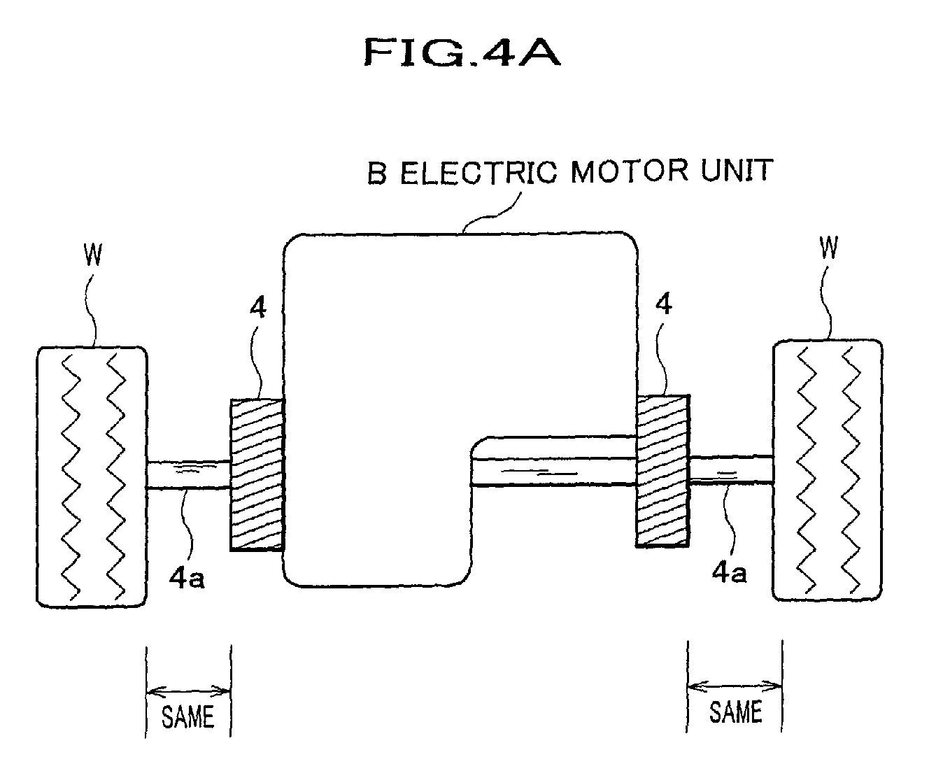
- the drive shafts 4a on right and left wheel sides may have the same length as illustrated in FIG. 4A.
- the drive shafts 104a on right and left wheel sides are different in the torsion amount due to the difference in lengths of the drive shafts 104a.
- the torsion amount is the same in both drive shafts 4a on right and left wheel sides, the running behavior of the vehicle will be stable during the drive of the vehicle.
- the term "accessories are placed on the electric motor unit B" means the same as described above, and this makes it possible to ensure space around the electric motor unit B.
- the reason why "the electric motor unit B is positioned behind the radiator 7" is to prevent the cooling capacity of the radiator 7 from being deteriorated due to interruption of a flow of wind toward the radiator 7 by arranging the electric motor unit B in front of the radiator 7. Therefore, by positively arranging the electric motor unit B behind the radiator 7, sufficient amount of air is led to the radiator 7 and wind passing through the radiator 7 (air distribution) can be distributed around the electric motor unit B that is compactly made.
- FIG. 5A is a diagrammatical sectional plan view of a motor room
- FIG. 5B is a diagrammatical sectional side view of the motor room.
- wind passing through the radiator 7 hits against the electric motor unit B and detours along the electric motor unit B in right and left directions. Also, wind passing through the radiator 7 is oriented downward so as to detour along the electric motor unit B in the downward direction .
- the flow of air flowing under the electric motor unit B is a mainstream w1
- the flow of air flowing in the right and left directions of the electric motor unit B is a sidestream w2.
- the fuel cell electric vehicle is better than the vehicle equipped with a gasoline engine in terms of energy efficiency.
- generated heat is exhausted through water (generated by electrochemical reaction) that is a heating medium. That is, the amount of heat exhaustion is small.
- the gasoline engine most of the generated heat can be exhausted as high temperature exhaust gas. That is, the amount of heat exhaustion is large.
- about 80 °C heat is exhausted (in the case of a PEM fuel cell). Therefore, it is difficult to exhaust heat effectively due to smaller temperature difference relative to the ambient air.
- high temperature heat having a greater temperature difference relative to the ambient air can be exhausted. Therefore, it is possible to exhaust heat effectively.
- the fuel cell electric vehicle requires a large-sized radiator 7 (with a large surface area).
- the radiator 7 is arranged diagonally . This is to arrange the radiator 7 in the motor room R such that the utmost surface area of the radiator 7 is retained without increasing the height.
- the fuel cell electric vehicle requires more install space because an intake/exhaust system for the fuel cell, such as an air compressor 6, a silencer, and an intake/exhaust module, is arranged as various structures.
- a larger radiator 7 is required in the case of the fuel cell electric vehicle than in the case of other vehicles . Also, in the case of the fuel cell electric vehicle, more space is required in the motor room R because a number of equipment (accessories) has to be arranged in the motor room R.
- the install space of the electric motor unit B is decreased according to the invention.
- Increasing space of the motor room R improves air distribution of the radiator 7 and thus the cooling efficiency of the radiator 7 in the end.
- decreasing the install space of the electric motor unit B leads to extended space in the crushable zone or in the vehicle compartment. Working space for maintenance can also be readily retained.
- the present invention has been described as applying to a fuel cell electric vehicle, the invention is applicable to normal electric vehicles equipped with an electric motor and a secondary battery such as a nickel-metal hydride battery.
- the invention is also applicable to a hybrid vehicle (HEV), such as a series hybrid electric vehicle equipped with a traction motor and an engine for generating electricity so that the traction motor is driven by electric power generated at the engine.
- HEV hybrid vehicle
- the invention may be applied to other hybrid vehicles such as a parallel hybrid electric vehicle or a sprit hybrid electric vehicle.
- the fuel cell electric vehicle has been described as equipped with a high pressure hydrogen storage tank as a hydrogen supplying source.
- a storage tank made from hydrogen absorbing alloys may be employed.
- a reformer which reforms hydrocarbon fuel and generates hydrogen may be employed.
- the fuel cell electric vehicle may or may not be equipped with an energy buffer such as a capacitor or a battery.
- a motor structure of an electric vehicle which is driven by an electric motor.
- the motor structure comprises an electric motor unit including the electric motor and differential gears, and a radiator as cooling means of the electric vehicle. Accessories are mounted on the electric motor unit.
- the radiator is positioned at a front side of the electric vehicle and in front of the electric motor unit.
- one of universal joints each of which connects a drive shaft on the differential gears side and a drive shaft on a wheel side, is adjacent to a side of the electric motor in the form of a cylinder.
Landscapes
- Engineering & Computer Science (AREA)
- Chemical & Material Sciences (AREA)
- Combustion & Propulsion (AREA)
- Transportation (AREA)
- Mechanical Engineering (AREA)
- Electric Propulsion And Braking For Vehicles (AREA)
- Arrangement Or Mounting Of Propulsion Units For Vehicles (AREA)
- Cooling, Air Intake And Gas Exhaust, And Fuel Tank Arrangements In Propulsion Units (AREA)
- Motor Power Transmission Devices (AREA)
Abstract
Description
- The present invention relates to a motor structure of an electric vehicle, which requires less install space upon installing an electric motor unit in a motor room.
- Electric vehicles equipped with an accumulator battery or a fuel cell and driven by a traction motor has been drawn attention because they do not emit carbon dioxide gas during the running. Electric vehicles are provided with an electric motor in a motor room and a driving force generated at the electric motor is transmitted to driving wheels via a transmission, differential gears, and universal joints.
- FIG. 6 is a schematic plan view of a conventional electric motor unit consisting of an electric motor, a transmission, and differential gears. As seen in this figure, the
electric motor 101 and thedifferential gears 103, which form the electric motor unit B, are arranged such that a rotatingshaft 101a of theelectric motor 101 anddrive shafts differential gears 103 are positioned parallel to each other. - In this figure,
reference numerals shafts reference numeral 103a designates a shaft on the differential gears side and thereference numeral 104a designates a drive shaft on a wheel side. - When considering a collision of a vehicle, it is preferable that the vehicle is provided with a larger crushable zone for absorption of impact. More free space in the motor room is also desired in terms of maintenance. Also, improving the air distribution of the radiator is desired in terms of cooling the motor. Further, it is desired to improve the comfortability with extended vehicle compartment space. Therefore, less install space of the equipment is required in the motor room of the electric vehicle equipped with the electric motor unit B such as illustrated in FIG. 6.
- In view of the above, the purpose of the present invention is to provide a motor structure of an electric vehicle, which requires less install space.
- According to a first aspect of the invention, there is provided a motor structure of an electric vehicle which is driven by an electric motor. The motor structure comprises an electric motor unit including the electric motor and differential gears, and a radiator as cooling means of the electric vehicle. Accessories are mounted on the electric motor unit. The radiator is positioned at a front side of the electric vehicle and in front of the electric motor unit. In this motor structure, one of universal joints, each of which connects a drive shaft on the differential gears side and a drive shaft on a wheel side, is adjacent to a side of the electric motor in the form of a cylinder.
- Herein, the term "side of the electric motor" indicates either right or left side of the electric motor (side facing either one of the driving wheels) , as shown in the preferred embodiment to be described later, when mounted on the electric vehicle, and to be more specific, at a side surface of the electric motor, where the transmission and the differential gears are not arranged. In this structure, since the side surface of the electric motor can be utilized to fix one of the universal joints, it is possible that the universal joints are positioned adjacently to the electric motor, thereby decreasing the distance between the shaft of the electric motor and the shafts of the driving wheels. Further, if accessories are positioned above the electric motor, more space is available in the fore and aft direction of the electric motor. Herein, the term "one of universal joints" indicates one of the right and left universal joints, and the term "cylinder" includes not only a complete cylinder but also other shapes such as barrel, square column, and the like.
- According to a second aspect of the invention, the aforementioned electric motor may be driven by a fuel cell and the accessories may include a power control unit controlling electric power from the fuel cell and an intake system supplying air to the fuel cell.
- In this structure, sufficient space is retained, for example, in the motor room of a fuel cell electric vehicle provided with a variety of equipment. Further, it is possible to cool down the fuel cell reliably even though the temperature of generated heat is low in the fuel cell and effective cooling is difficult.
- According to a third aspect of the invention, in the aforementioned motor structure, drive shafts on right and left wheel sides may have substantially the same length.
- In this structure, since the same torsion amount occurs in both drive shafts on right and left wheel sides , the running behavior of the vehicle will be stable during the drive of the vehicle.
- A preferred embodiment of the present invention will be described below, by way of example only, with reference to the accompanying drawings, in which:
- FIG. 1 is a diagrammatical vertical sectional view of a fuel cell electric vehicle to which is applied a motor structure according to the invention;
- FIG. 2 is a perspective view of an electric motor unit shown in FIG. 1;
- FIG. 3 is a schematic plan view of the electric motor unit of FIG. 1 including an electric motor, a transmission, and differential gears;
- FIG. 4A is a schematic plan view comparing lengths of right and left drive shafts according to the invention, and FIG. 4B is a schematic plan view comparing lengths of right and left drive shafts according to prior art;
- FIGS. 5A and 5B are views explaining the air distribution of a radiator shown in FIG. 1, wherein FIG. 5A is a diagrammatical sectional plan view of a motor room and FIG. 5B is a diagrammatical sectional side view of the motor room; and
- FIG. 6 is a schematic plan view of a conventional electric motor unit including an electric motor, a transmission, and differential gears.
-
- With reference to the accompanying drawings, a preferred embodiment of the invention will be described.
- FIG. 1 is a diagrammatical vertical sectional view of a fuel cell electric vehicle to which is applied a motor structure according to the invention. FIG. 2 is a perspective view of an electric motor unit shown in FIG. 1. FIG. 3 is a schematic plan view of the electric motor unit.
- As shown in FIG. 1, a fuel cell electric vehicle is provided with an
electric motor 1, atransmission 2,differential gears 3,universal joints 4, a power control unit (hereinafter referred to as "PCU") 5, anair compressor 6 as an intake system, and aradiator 7, in a motor room R that is arranged at a front side of the vehicle. The vehicle is provided with aFC box 8 under the floor of a vehicle compartment and acapacitor 9 and a high pressurehydrogen storage tank 10 at a rear side of the vehicle. Of these, theelectric motor 1, thetransmission 2, and thedifferential gears 3 form the electric motor unit B. PCU 5 is positioned right above the electric motor unit B, and theair compressor 6 is positioned above the electric motor unit B so that sufficient space can be retained in the fore and aft direction of the electric motor unit B by effectively utilizing space extending above the electric motor unit B. In other words, accessories such as PCU 5 and theair compressor 6 are placed on the electric motor unit B so as to use the space effectively. - A fuel cell is accommodated in the
FC box 8 so that oxygen supplied from the high pressurehydrogen storage tank 10 and air supplied from theair compressor 6 react to generate electricity. Thecapacitor 9 levels load fluctuation of the fuel cell. Theradiator 7 cools theelectric motor 1, the fuel cell, and the like. - As shown in FIG. 2, the electric motor unit B is an integrated structure when viewing from outside. In FIG. 2, the near side of the drawing faces to the rear side of the vehicle, and the far side of the drawing faces to the front side of the vehicle (viz. to the radiator 7). Therefore, the right-hand side of the drawing corresponds to the front right driving wheel side.
- As seen in FIGS. 2 and 3, the
electric motor 1 is in the form of a cylinder (substantially in the form of a complete cylinder), and forms a main part of the electric motor unit B. Thetransmission 2 is positioned at the left side of theelectric motor 1, so that rotation force generated by theelectric motor 1 is inputted through the rotating shaft 1a. Thetransmission 2 converts rotation speed of the rotating shaft 1a of theelectric motor 1 and input the same to thedifferential gears 3 that is positioned at the rear left side of the electric motor unit B. Thedifferential gears 3 adjust the difference of the rotation speed between right and left driving wheelsW. Drive shafts 3a on the differential gears side that extend from thedifferential gears 3 to the driving wheels W are connected to outer side (wheel side)drive shafts 4a throughuniversal joints 4. - The axis line of the rotating shaft 1a is parallel to the axis line of the
drive shafts - As shown in FIGS. 2 and 3, the right side
universal joint 4 is supported by a supportingstay 4b fixed at the right side surface of the electric motor 1 (electric motor unit B). That is , the right sideuniversal joint 4 is adjacent to the side surface (right side surface) of theelectric motor 1 substantially in the form of a complete cylinder. As seen in FIG. 6 illustrating a prior art example, if theuniversal joint 4 is supported at a near side (outer cylindrical surface) of the electric motor 1 (101) instead of at the side surface, sufficient stiffness is required at this surface to support the universal joint 4 (104), leading to increased thickness of the electric motor B at the outer cylindrical surface. This makes it impossible to arrange the rotating shaft 1a of theelectric motor 1 and thedrive shafts universal joint 4 is arranged at the side surface of theelectric motor 1, it is possible to arrange the rotating shaft 1a of theelectric motor 1 and thedrive shafts - Therefore, more space is available for the crushable zone and the maintenance space or for the vehicle compartment.
- Further, according to the invention, the
drive shafts 4a on right and left wheel sides may have the same length as illustrated in FIG. 4A. In the prior art example shown in FIG. 4B, thedrive shafts 104a on right and left wheel sides are different in the torsion amount due to the difference in lengths of thedrive shafts 104a. However, in the preferred embodiment of the invention, since the torsion amount is the same in both driveshafts 4a on right and left wheel sides, the running behavior of the vehicle will be stable during the drive of the vehicle. - Further, as seen in FIG. 1, accessories such as
PCU 5, anair compressor 6 are placed on the electric motor unit B, and theradiator 7 as cooling means of the fuel cell electric vehicle is positioned at the front side of the vehicle while the electric motor unit B is positioned behind theradiator 7. Herein, the term "accessories are placed on the electric motor unit B" means the same as described above, and this makes it possible to ensure space around the electric motor unit B. Meanwhile, the reason why "the electric motor unit B is positioned behind theradiator 7" is to prevent the cooling capacity of theradiator 7 from being deteriorated due to interruption of a flow of wind toward theradiator 7 by arranging the electric motor unit B in front of theradiator 7. Therefore, by positively arranging the electric motor unit B behind theradiator 7, sufficient amount of air is led to theradiator 7 and wind passing through the radiator 7 (air distribution) can be distributed around the electric motor unit B that is compactly made. - With reference to FIGS. 5A and 5B, air distribution of the
radiator 7 will be described. FIG. 5A is a diagrammatical sectional plan view of a motor room, and FIG. 5B is a diagrammatical sectional side view of the motor room. - As shown FIGS. 5A and 5B, wind passing through the
radiator 7 hits against the electric motor unit B and detours along the electric motor unit B in right and left directions. Also, wind passing through theradiator 7 is oriented downward so as to detour along the electric motor unit B in the downward direction . Herein, the flow of air flowing under the electric motor unit B is a mainstream w1, and the flow of air flowing in the right and left directions of the electric motor unit B is a sidestream w2. - The fuel cell electric vehicle is better than the vehicle equipped with a gasoline engine in terms of energy efficiency. However, in the fuel cell electric vehicle, generated heat is exhausted through water (generated by electrochemical reaction) that is a heating medium. That is, the amount of heat exhaustion is small. Meanwhile, in the gasoline engine, most of the generated heat can be exhausted as high temperature exhaust gas. That is, the amount of heat exhaustion is large. Further, in the fuel cell electric vehicle, about 80 °C heat is exhausted (in the case of a PEM fuel cell). Therefore, it is difficult to exhaust heat effectively due to smaller temperature difference relative to the ambient air. Meanwhile, in the gasoline engine, high temperature heat having a greater temperature difference relative to the ambient air can be exhausted. Therefore, it is possible to exhaust heat effectively.
- For the reasons set forth above, the fuel cell electric vehicle requires a large-sized radiator 7 (with a large surface area). As best seen in FIGS . 1 and 5B, the
radiator 7 is arranged diagonally . This is to arrange theradiator 7 in the motor room R such that the utmost surface area of theradiator 7 is retained without increasing the height. - Unlike an electric vehicle equipped with a battery, the fuel cell electric vehicle requires more install space because an intake/exhaust system for the fuel cell, such as an
air compressor 6, a silencer, and an intake/exhaust module, is arranged as various structures. - In other words, a
larger radiator 7 is required in the case of the fuel cell electric vehicle than in the case of other vehicles . Also, in the case of the fuel cell electric vehicle, more space is required in the motor room R because a number of equipment (accessories) has to be arranged in the motor room R. - In this regard, when viewing from above, the install space of the electric motor unit B, especially the install space in the fore and aft direction, is decreased according to the invention. This leads to increased space of the motor room R. Increasing space of the motor room R improves air distribution of the
radiator 7 and thus the cooling efficiency of theradiator 7 in the end. Meanwhile, decreasing the install space of the electric motor unit B leads to extended space in the crushable zone or in the vehicle compartment. Working space for maintenance can also be readily retained. - While the invention has been described in detail with reference to a specific embodiment thereof, it will be apparent to one skilled in the art that various changes and modifications may be made without departing from the scope of the claims.
- Although the present invention has been described as applying to a fuel cell electric vehicle, the invention is applicable to normal electric vehicles equipped with an electric motor and a secondary battery such as a nickel-metal hydride battery. The invention is also applicable to a hybrid vehicle (HEV), such as a series hybrid electric vehicle equipped with a traction motor and an engine for generating electricity so that the traction motor is driven by electric power generated at the engine. Of course, the invention may be applied to other hybrid vehicles such as a parallel hybrid electric vehicle or a sprit hybrid electric vehicle.
- The fuel cell electric vehicle has been described as equipped with a high pressure hydrogen storage tank as a hydrogen supplying source. However, a storage tank made from hydrogen absorbing alloys may be employed. Also, a reformer which reforms hydrocarbon fuel and generates hydrogen may be employed. Of course, the fuel cell electric vehicle may or may not be equipped with an energy buffer such as a capacitor or a battery.
- A motor structure of an electric vehicle which is driven by an electric motor. The motor structure comprises an electric motor unit including the electric motor and differential gears, and a radiator as cooling means of the electric vehicle. Accessories are mounted on the electric motor unit. The radiator is positioned at a front side of the electric vehicle and in front of the electric motor unit. In this motor structure, one of universal joints, each of which connects a drive shaft on the differential gears side and a drive shaft on a wheel side, is adjacent to a side of the electric motor in the form of a cylinder.
Claims (4)
- A motor structure of an electric vehicle, the electric vehicle being driven by an electric motor, comprising:wherein one of universal joints each connecting a drive shaft on the differential gears side and a drive shaft on a wheel side is adjacent to a side of the electric motor in the form of a cylinder.an electric motor unit including the electric motor and differential gears, onto which is mounted accessories;a radiator, as cooling means of the electric vehicle, positioned at a front side of the electric vehicle and in front of the electric motor unit;
- A motor structure of an electric vehicle according to claim 1, wherein said electric motor is driven by a fuel cell and wherein said accessories include a power control unit controlling electric power from the fuel cell and an intake system supplying air to the fuel cell.
- A motor structure of an electric vehicle according to claim 1, wherein drive shafts on right and left wheel sides have substantially the same length.
- A motor structure of an electric vehicle according to claim 2, wherein drive shafts on right and left wheel sides have substantially the same length.
Applications Claiming Priority (2)
| Application Number | Priority Date | Filing Date | Title |
|---|---|---|---|
| JP2001264768A JP2003072392A (en) | 2001-08-31 | 2001-08-31 | Electric motor structure of electric vehicle |
| JP2001264768 | 2001-08-31 |
Publications (2)
| Publication Number | Publication Date |
|---|---|
| EP1288050A1 true EP1288050A1 (en) | 2003-03-05 |
| EP1288050B1 EP1288050B1 (en) | 2004-05-06 |
Family
ID=19091319
Family Applications (1)
| Application Number | Title | Priority Date | Filing Date |
|---|---|---|---|
| EP02017937A Expired - Lifetime EP1288050B1 (en) | 2001-08-31 | 2002-08-09 | Motor structure of an electric vehicle |
Country Status (5)
| Country | Link |
|---|---|
| US (1) | US6973982B2 (en) |
| EP (1) | EP1288050B1 (en) |
| JP (1) | JP2003072392A (en) |
| CA (1) | CA2397311A1 (en) |
| DE (1) | DE60200440T2 (en) |
Cited By (5)
| Publication number | Priority date | Publication date | Assignee | Title |
|---|---|---|---|---|
| EP1533161A4 (en) * | 2002-06-10 | 2005-09-14 | Toyota Motor Co Ltd | VEHICLE EQUIPPED WITH FUEL CELLS |
| WO2013061153A1 (en) * | 2011-10-27 | 2013-05-02 | Toyota Jidosha Kabushiki Kaisha | Vehicle front structure |
| EP2942218A1 (en) * | 2014-05-05 | 2015-11-11 | Movimotor S.r.l. | Drive unit for electric vehicles |
| FR3029494A1 (en) * | 2014-12-08 | 2016-06-10 | Peugeot Citroen Automobiles Sa | DEVICE AND METHOD FOR ASSEMBLING A TRANSMISSION IN THE OUTPUT OF A GEARBOX OF A MOTORPOWER GROUP FOR A MOTOR VEHICLE |
| FR3113625A1 (en) * | 2020-08-25 | 2022-03-04 | Psa Automobiles Sa | POWERTRAIN INCLUDING A MECHANICAL STIFFENING DEVICE |
Families Citing this family (35)
| Publication number | Priority date | Publication date | Assignee | Title |
|---|---|---|---|---|
| EP1038346A2 (en) * | 1997-10-21 | 2000-09-27 | Stridsberg Innovation Ab | A hybrid powertrain |
| US7134517B1 (en) * | 2003-02-10 | 2006-11-14 | Kaiser Clements J | Dual electric motor four wheel drive personnel carrier |
| US8469133B2 (en) * | 2003-02-10 | 2013-06-25 | Bb Buggies Inc. | Dual electric motor four wheel drive personnel carrier |
| JP2006219034A (en) * | 2005-02-10 | 2006-08-24 | Denso Corp | Driving permission device |
| US8356682B2 (en) * | 2005-04-04 | 2013-01-22 | Delphi Technologies, Inc. | Fuel cell system using external heat sources for maintaining internal temperature |
| US7971670B2 (en) * | 2005-10-25 | 2011-07-05 | Nissan Motor Co., Ltd. | Fuel cell electric vehicle |
| CN100346996C (en) * | 2006-06-06 | 2007-11-07 | 北京理工大学 | Motor drive and transmission device of electric automobile |
| US8113308B2 (en) * | 2008-07-02 | 2012-02-14 | Illinois Institute Of Technology | Integrated electric motor differential for hybrid electric vehicles |
| US8517127B2 (en) * | 2009-04-15 | 2013-08-27 | Nissan Motor Co., Ltd. | Vehicle component mounting arrangement |
| DE102009033531A1 (en) * | 2009-07-10 | 2011-01-20 | Dr. Ing. H.C. F. Porsche Aktiengesellschaft | Drive device for a motor vehicle with an electric machine having portal axis |
| US8479851B2 (en) * | 2009-10-27 | 2013-07-09 | Magna Powertrain Of America, Inc. | Electric drive unit with modular motor assembly |
| DE102010010438A1 (en) * | 2010-02-26 | 2011-09-01 | Dr. Ing. H.C. F. Porsche Aktiengesellschaft | Suspension for a motor vehicle with an electrical axis |
| CN101830171A (en) * | 2010-04-30 | 2010-09-15 | 奇瑞汽车股份有限公司 | Power assembly of electric automobile |
| JP4840541B1 (en) * | 2010-07-06 | 2011-12-21 | トヨタ自動車株式会社 | Fuel cell mounting structure |
| JP5561156B2 (en) * | 2010-12-28 | 2014-07-30 | マツダ株式会社 | Electric vehicle |
| JP5800214B2 (en) | 2011-02-23 | 2015-10-28 | スズキ株式会社 | Electric vehicle power unit suspension structure |
| WO2012132698A1 (en) * | 2011-03-29 | 2012-10-04 | 株式会社小松製作所 | Electric forklift |
| CN102815193A (en) * | 2011-06-08 | 2012-12-12 | 朱淑怡 | Hybrid electric vehicle |
| JP2013103582A (en) * | 2011-11-14 | 2013-05-30 | Honda Motor Co Ltd | Structure for mounting power control unit on vehicle body |
| CN103298636B (en) * | 2011-11-14 | 2014-07-09 | 本田技研工业株式会社 | electric car |
| US8936120B2 (en) * | 2011-12-29 | 2015-01-20 | Kawasaki Jukogyo Kabushiki Kaisha | Utility vehicle having a front electric motor |
| DE102012111964A1 (en) * | 2012-12-07 | 2014-06-26 | Dr. Ing. H.C. F. Porsche Aktiengesellschaft | Final drive unit for motor vehicle, has cap-shaped bearing plate for the drive shaft of electric machine, that is arranged at side remote from gear unit side of electric machine, and is provided with bearing point for the drive shaft |
| DE102012111962B4 (en) * | 2012-12-07 | 2025-03-13 | Dr. Ing. H.C. F. Porsche Aktiengesellschaft | Axle drive unit for a motor vehicle |
| DE102012111967B4 (en) * | 2012-12-07 | 2025-03-13 | Dr. Ing. H.C. F. Porsche Aktiengesellschaft | Axle drive unit for a motor vehicle |
| DE102013201122A1 (en) | 2013-01-24 | 2014-07-24 | Bayerische Motoren Werke Aktiengesellschaft | Motor vehicle with a fuel cell |
| EP2977251A1 (en) * | 2013-03-18 | 2016-01-27 | Hitachi Automotive Systems, Ltd. | Drive device for electric vehicle |
| US9126581B2 (en) * | 2013-05-08 | 2015-09-08 | GM Global Technology Operations LLC | Hybrid powertrain and modular rear drive unit for same |
| US9278618B2 (en) * | 2013-10-29 | 2016-03-08 | GM Global Technology Operations LLC | Powertrain including an electric motor/generator and a final drive unit connected to the electric motor/generator |
| JP6128010B2 (en) | 2014-02-25 | 2017-05-17 | トヨタ自動車株式会社 | Electric vehicle |
| JP2017019331A (en) * | 2015-07-08 | 2017-01-26 | Ntn株式会社 | Motor driving device for vehicle |
| EP3390128B1 (en) | 2015-12-17 | 2023-09-27 | Allison Transmission, Inc. | Axle assembly for a vehicle |
| JP6688825B2 (en) * | 2018-03-28 | 2020-04-28 | 本田技研工業株式会社 | vehicle |
| JP7120082B2 (en) * | 2019-03-06 | 2022-08-17 | トヨタ自動車株式会社 | vehicle front structure |
| US11420514B2 (en) * | 2020-07-14 | 2022-08-23 | Allison Transmission, Inc. | Multispeed transaxle with sprung powertrain mounting and methods therefor |
| DE102021200281A1 (en) | 2021-01-14 | 2022-07-14 | Zf Friedrichshafen Ag | Driving device for an electrically driven vehicle |
Citations (4)
| Publication number | Priority date | Publication date | Assignee | Title |
|---|---|---|---|---|
| US5585681A (en) * | 1993-05-28 | 1996-12-17 | Steyr-Daimler Puch Ag | Liquid-cooled drive unit for an electric motor vehicle |
| US5632157A (en) * | 1990-05-24 | 1997-05-27 | Seiko Epson Corporation | Electric automobile |
| US5662184A (en) * | 1994-04-12 | 1997-09-02 | Daimler-Benz Ag | Arrangement of a drive unit in an electric vehicle |
| US6059684A (en) * | 1997-04-17 | 2000-05-09 | Aisin Aw Co., Ltd. | Drive train for electric cars |
Family Cites Families (7)
| Publication number | Priority date | Publication date | Assignee | Title |
|---|---|---|---|---|
| JP2962071B2 (en) * | 1992-09-11 | 1999-10-12 | トヨタ自動車株式会社 | Drive for electric vehicles |
| DE4412450A1 (en) * | 1994-04-12 | 1995-10-26 | Daimler Benz Ag | Arrangement of a drive unit in an electric vehicle |
| US5807180A (en) * | 1997-08-28 | 1998-09-15 | Dana Corporation | Constant velocity universal joint shaft and inner race combination |
| JP3685920B2 (en) * | 1997-09-14 | 2005-08-24 | 本田技研工業株式会社 | Electric motor controller for hybrid vehicles |
| US6053266A (en) * | 1997-12-01 | 2000-04-25 | Dbb Fuel Cell Engines Gmbh | Fuel cell engine having a propulsion motor operatively connected to drive a fluid supply device |
| US6223843B1 (en) * | 1998-12-16 | 2001-05-01 | General Motors Corporation | Electrochemical propulsion system |
| DE10026268A1 (en) * | 1999-05-28 | 2000-12-07 | Honda Motor Co Ltd | Fuel cell powered electric vehicle has fuel tank, fuel reformer, fuel cell, electrical energy storage device arranged in series in longitudinal vehicle direction below floor of vehicle |
-
2001
- 2001-08-31 JP JP2001264768A patent/JP2003072392A/en not_active Withdrawn
-
2002
- 2002-08-09 EP EP02017937A patent/EP1288050B1/en not_active Expired - Lifetime
- 2002-08-09 CA CA002397311A patent/CA2397311A1/en not_active Abandoned
- 2002-08-09 DE DE60200440T patent/DE60200440T2/en not_active Expired - Fee Related
- 2002-08-16 US US10/222,082 patent/US6973982B2/en not_active Expired - Fee Related
Patent Citations (4)
| Publication number | Priority date | Publication date | Assignee | Title |
|---|---|---|---|---|
| US5632157A (en) * | 1990-05-24 | 1997-05-27 | Seiko Epson Corporation | Electric automobile |
| US5585681A (en) * | 1993-05-28 | 1996-12-17 | Steyr-Daimler Puch Ag | Liquid-cooled drive unit for an electric motor vehicle |
| US5662184A (en) * | 1994-04-12 | 1997-09-02 | Daimler-Benz Ag | Arrangement of a drive unit in an electric vehicle |
| US6059684A (en) * | 1997-04-17 | 2000-05-09 | Aisin Aw Co., Ltd. | Drive train for electric cars |
Cited By (9)
| Publication number | Priority date | Publication date | Assignee | Title |
|---|---|---|---|---|
| EP1533161A4 (en) * | 2002-06-10 | 2005-09-14 | Toyota Motor Co Ltd | VEHICLE EQUIPPED WITH FUEL CELLS |
| EP1717083A3 (en) * | 2002-06-10 | 2006-12-06 | Toyota Jidosha Kabushiki Kaisha | Fuel cell vehicle |
| US7270202B2 (en) | 2002-06-10 | 2007-09-18 | Toyota Jidosha Kabushiki Kaisha | Fuel cell vehicle |
| US7703564B2 (en) | 2002-06-10 | 2010-04-27 | Toyota Jidosha Kabuhsiki Kaisha | Fuel cell vehicle |
| WO2013061153A1 (en) * | 2011-10-27 | 2013-05-02 | Toyota Jidosha Kabushiki Kaisha | Vehicle front structure |
| US9010479B2 (en) | 2011-10-27 | 2015-04-21 | Toyota Jidosha Kabushiki Kaisha | Vehicle front structure |
| EP2942218A1 (en) * | 2014-05-05 | 2015-11-11 | Movimotor S.r.l. | Drive unit for electric vehicles |
| FR3029494A1 (en) * | 2014-12-08 | 2016-06-10 | Peugeot Citroen Automobiles Sa | DEVICE AND METHOD FOR ASSEMBLING A TRANSMISSION IN THE OUTPUT OF A GEARBOX OF A MOTORPOWER GROUP FOR A MOTOR VEHICLE |
| FR3113625A1 (en) * | 2020-08-25 | 2022-03-04 | Psa Automobiles Sa | POWERTRAIN INCLUDING A MECHANICAL STIFFENING DEVICE |
Also Published As
| Publication number | Publication date |
|---|---|
| DE60200440T2 (en) | 2004-09-09 |
| CA2397311A1 (en) | 2003-02-28 |
| EP1288050B1 (en) | 2004-05-06 |
| US6973982B2 (en) | 2005-12-13 |
| DE60200440D1 (en) | 2004-06-09 |
| JP2003072392A (en) | 2003-03-12 |
| US20030042053A1 (en) | 2003-03-06 |
Similar Documents
| Publication | Publication Date | Title |
|---|---|---|
| EP1288050B1 (en) | Motor structure of an electric vehicle | |
| JP4339953B2 (en) | Arrangement structure of equipment in vehicle mounted with fuel cell system | |
| CN113787920B (en) | Chassis arrangement structure of hydrogen fuel tractor and hydrogen fuel tractor | |
| US7854282B2 (en) | Hybrid electric vehicle | |
| CA2282292C (en) | An electrochemical propulsion system | |
| US20060289224A1 (en) | Vehicle body structure | |
| US20120255799A1 (en) | Electric vehicle with range extender | |
| JP5761009B2 (en) | Hybrid vehicle | |
| EP1419926A2 (en) | On-board fuel cell powered electric vehicle | |
| US20010049040A1 (en) | Fuel cell system for an electric vehicle | |
| US12059949B2 (en) | Installation structure of electrical component module in vehicle | |
| JP2005299417A (en) | Exhaust heat generator and automobile equipped with the same | |
| JP2013500433A (en) | Thermal management system, vehicle and related method | |
| WO2005102759A1 (en) | Fuel cell vehicle with battery in vehicle floor | |
| US20060220405A1 (en) | Structure for arrangement of engine-associated vehicle components | |
| US20240300324A1 (en) | Vehicle body lower structure | |
| JP2006327325A (en) | Cooling device for fuel cell vehicle | |
| JP2004066889A (en) | Battery unit mounting structure | |
| KR101758176B1 (en) | Automobile | |
| WO2024004915A1 (en) | Agricultural work vehicle | |
| JP2000149974A (en) | Electric car | |
| JP2006302574A (en) | Vehicle fuel cell system and electric vehicle | |
| CN215398924U (en) | Heavy vehicle chassis and heavy vehicle | |
| JP7514954B2 (en) | Vehicle fuel cell system | |
| JP4192535B2 (en) | Fuel cell vehicle |
Legal Events
| Date | Code | Title | Description |
|---|---|---|---|
| PUAI | Public reference made under article 153(3) epc to a published international application that has entered the european phase |
Free format text: ORIGINAL CODE: 0009012 |
|
| AK | Designated contracting states |
Kind code of ref document: A1 Designated state(s): AT BE BG CH CY CZ DE DK EE ES FI FR GB GR IE IT LI LU MC NL PT SE SK TR Designated state(s): AT BE BG CH CY CZ DE DK EE ES FI FR GB GR IE IT LI LU MC NL PT SE SK TR |
|
| AX | Request for extension of the european patent |
Extension state: AL LT LV MK RO SI |
|
| 17P | Request for examination filed |
Effective date: 20030212 |
|
| GRAP | Despatch of communication of intention to grant a patent |
Free format text: ORIGINAL CODE: EPIDOSNIGR1 |
|
| AKX | Designation fees paid |
Designated state(s): DE FR GB |
|
| GRAS | Grant fee paid |
Free format text: ORIGINAL CODE: EPIDOSNIGR3 |
|
| GRAA | (expected) grant |
Free format text: ORIGINAL CODE: 0009210 |
|
| AK | Designated contracting states |
Kind code of ref document: B1 Designated state(s): DE FR GB |
|
| REG | Reference to a national code |
Ref country code: GB Ref legal event code: FG4D |
|
| REF | Corresponds to: |
Ref document number: 60200440 Country of ref document: DE Date of ref document: 20040609 Kind code of ref document: P |
|
| REG | Reference to a national code |
Ref country code: IE Ref legal event code: FG4D |
|
| ET | Fr: translation filed | ||
| PLBE | No opposition filed within time limit |
Free format text: ORIGINAL CODE: 0009261 |
|
| STAA | Information on the status of an ep patent application or granted ep patent |
Free format text: STATUS: NO OPPOSITION FILED WITHIN TIME LIMIT |
|
| 26N | No opposition filed |
Effective date: 20050208 |
|
| REG | Reference to a national code |
Ref country code: IE Ref legal event code: MM4A |
|
| PGFP | Annual fee paid to national office [announced via postgrant information from national office to epo] |
Ref country code: DE Payment date: 20080821 Year of fee payment: 7 |
|
| PGFP | Annual fee paid to national office [announced via postgrant information from national office to epo] |
Ref country code: FR Payment date: 20080818 Year of fee payment: 7 |
|
| PGFP | Annual fee paid to national office [announced via postgrant information from national office to epo] |
Ref country code: GB Payment date: 20080723 Year of fee payment: 7 |
|
| GBPC | Gb: european patent ceased through non-payment of renewal fee |
Effective date: 20090809 |
|
| REG | Reference to a national code |
Ref country code: FR Ref legal event code: ST Effective date: 20100430 |
|
| PG25 | Lapsed in a contracting state [announced via postgrant information from national office to epo] |
Ref country code: FR Free format text: LAPSE BECAUSE OF NON-PAYMENT OF DUE FEES Effective date: 20090831 Ref country code: DE Free format text: LAPSE BECAUSE OF NON-PAYMENT OF DUE FEES Effective date: 20100302 |
|
| PG25 | Lapsed in a contracting state [announced via postgrant information from national office to epo] |
Ref country code: GB Free format text: LAPSE BECAUSE OF NON-PAYMENT OF DUE FEES Effective date: 20090809 |