EP1288042A1 - Openable vehicle roof with a movable front and rear closing element - Google Patents
Openable vehicle roof with a movable front and rear closing element Download PDFInfo
- Publication number
- EP1288042A1 EP1288042A1 EP02013115A EP02013115A EP1288042A1 EP 1288042 A1 EP1288042 A1 EP 1288042A1 EP 02013115 A EP02013115 A EP 02013115A EP 02013115 A EP02013115 A EP 02013115A EP 1288042 A1 EP1288042 A1 EP 1288042A1
- Authority
- EP
- European Patent Office
- Prior art keywords
- closing element
- vehicle roof
- fixed element
- roof according
- vehicle
- Prior art date
- Legal status (The legal status is an assumption and is not a legal conclusion. Google has not performed a legal analysis and makes no representation as to the accuracy of the status listed.)
- Granted
Links
Images

Classifications
-
- B—PERFORMING OPERATIONS; TRANSPORTING
- B60—VEHICLES IN GENERAL
- B60J—WINDOWS, WINDSCREENS, NON-FIXED ROOFS, DOORS, OR SIMILAR DEVICES FOR VEHICLES; REMOVABLE EXTERNAL PROTECTIVE COVERINGS SPECIALLY ADAPTED FOR VEHICLES
- B60J7/00—Non-fixed roofs; Roofs with movable panels, e.g. rotary sunroofs
- B60J7/02—Non-fixed roofs; Roofs with movable panels, e.g. rotary sunroofs of sliding type, e.g. comprising guide shoes
- B60J7/04—Non-fixed roofs; Roofs with movable panels, e.g. rotary sunroofs of sliding type, e.g. comprising guide shoes with rigid plate-like element or elements, e.g. open roofs with harmonica-type folding rigid panels
- B60J7/047—Non-fixed roofs; Roofs with movable panels, e.g. rotary sunroofs of sliding type, e.g. comprising guide shoes with rigid plate-like element or elements, e.g. open roofs with harmonica-type folding rigid panels movable to overlapping or nested relationship
Definitions
- the present invention relates to an openable vehicle roof with a front and a rear closing element according to the preamble of claim 1.
- Such a generic vehicle roof is for example from the DE 43 35 653 A1 known, which is designed as a sliding roof, in which a cover made of sight glass under a sight glass pane fixed to the body, which forms the outer skin of the roof in this area can be pushed behind to reveal a roof opening.
- the two Glass elements can be used as multi-layer sun protection glass or as be formed of phototropic glass. To implement additional sun protection and / or to darken the interior can be in the interior of the vehicle a blind can be provided below the glass elements.
- a disadvantage of such a construction is that the cover when it is to the rear is pushed under the fixed glass element, unprotected onto one Rear passenger drives up, resulting in a risk of objects being trapped or body parts in the laterally arranged adjustment mechanism or guide rail for the lid and in the area of the lid rear edge or one provided there Gully results, or that protruding edges like the lid trailing edge Can cause injuries in a crash.
- Another disadvantage is that the sun protection with a conventional solution with sliding parts at least partially the front or the rear roof part closes or darkens. If instead one or more blinds larger space is required. Another disadvantage is that the blinds are straight in the transverse direction and thus the arched Roof contour can not follow, and that in an electrical variant electrical Drives must be accommodated.
- a sunroof in which one over a solid roof covering that can be pushed back and two side by side transparent sliding plates are provided, which from a rest position, in which they are between the rear solid roof skin and one below arranged fabric covering are slidable to the front when open Cover the resulting roof opening in a transparent manner.
- German patent application 101 14 497.0 there is a vehicle roof described an openable transparent lid, which is an upper transparent Disc and a lower transparent disc arranged underneath has, wherein the upper disc or the lower disc with a coating or glued film formed layer of electrochromic or liquid crystal material is provided, the transmission or transparency is adjustable by applying a voltage. Furthermore, one is for example cylindrical lighting device provided laterally between the two Glass panes or arranged on the side edges of the lower glass pane is to couple light into the lower pane and use it as a light source use.
- the object is achieved by a vehicle roof with the features of claim 1 solved.
- this solution it is advantageous that the at least partially transparent fixed element below the rear closing element on the one hand the area of the front closing element when this is to the rear is pushed under the rear closing element, is covered and thus a Pinch protection is realized, and on the other hand through the transparency of the Fixed element by the incidence of light through the front and the rear Closing element achieved optical impression is not significantly affected.
- the front closing element is preferably a glass or plastic cover. Furthermore, the front closing element can be used as a cover for a sliding roof or a sunroof.
- the rear closing element can also be a glass or plastic cover and it can be fixed, but it is preferably one with its Rear edge in a ventilation position hinged lid, so that a friend Ventilation of the vehicle can be supported.
- the fixed element contains a layer whose Transmission is adjustable by the vehicle user.
- the layer is e.g. B. as LCD, EC or SPD coating formed.
- the layer can be on the fixed element can be glued on LCD, EC or SPD film.
- the fixed element is expediently designed as a glass or plastic plate.
- a vehicle roof according to the invention comprises a front one Closing element 10, which is shown in the closed position, and one behind it horizontally arranged rear closing element 12, which in the illustrated state close together a roof opening 14 in a fixed roof surface 16.
- the front closing element is a Lid made of translucent material, preferably glass or plastic, the by means of a known and not shown adjustment mechanism a pure Sunroof function or a sunroof function can perform. In both cases, the adjustment mechanism is designed so that the front cover 10 by means of a drive known and not shown to the rear can be pushed under the rear closing element 12, at least around the roof opening 14 to be exposed in the front area.
- the rear closing element 12 is also shown in FIG. 1 as a cover made of transparent Material, preferably glass or plastic, formed, the rear Lid 12 fixed, i.e. not adjustable, or with its rear edge in one Ventilation position can be formed.
- a translucent fixed element 18 is provided below the rear cover 12, which is mounted fixed to the vehicle and preferably as a glass or Plastic plate is formed. Includes behind the fixed element 18 Fixed sky 20 on. 3, the fixed element 18 comprises the glass or Plastic plate 22 and one on the top or, as shown in Fig. 3, on the Underside of the plate 22 attached layer 24, the transmission of which via a applied voltage is adjustable by the vehicle user.
- Layer 24 can thereby, for example, as a liquid crystal (LCD) coating, SPD (suspended particle device) coating or as an electrochromic (EC) coating on the Plate 22 or be designed as a corresponding glued film.
- LCD liquid crystal
- SPD suspended particle device
- EC electrochromic
- the Layer 24 serves to prevent undesired strong light from entering the vehicle interior 26 through the transparent rear cover 12 and the transparent Disk or plate 22 through an appropriate control of the To prevent transmission of layer 24. In this way, a darkening or sun protection without additional and in particular moving parts, such as a roller blind or a sliding roof can be achieved.
- Lighting device 28 is provided, which in the roof longitudinal direction in cylindrical shape extends to light across the side edge of plate 22 into the Coupling plate 22.
- the plate 22 is preferably designed so that it has a plurality of reflection surfaces formed within the plate 22, which reflect the coupled light downwards towards the vehicle interior 26, around the fixed element 18 as a light source for the vehicle interior 26 to be able to use.
- a suitable design of the disc or plate 22 of the Fixed element 18 is described in US Pat. No. 5,079,675. Details regarding the design the lighting device 28 and its arrangement with respect to the Fixed elements 18 are in the above-mentioned older German patent application No. 101 14 497.0.
- the lighting device 28 be designed so that they have an optional lighting in at least two different colors allowed and the light intensity is adjustable.
- the lighting device 28 by LEDs or by a Fluorescent tube or discharge tube can be formed.
- a position of the front cover 10 is shown, in which this is pushed back between the rear cover 12 and the fixed element 18 is.
- the fixed element 18 acts as protection for a rear passenger with respect to the front Cover 10, in particular a pinch protection in the area of the side Adjustment and guidance mechanism arranged below the rear cover 12 for the front cover 10 and a pinch protection in the area of Trailing edge of the front cover 10 or in the area provided there Gully (not shown) can be realized.
- the fixed element 18 Due to the described design of the fixed element 18 can be easily Way a pinch protection without significant impairment of the by transparent design of the front cover 10 and the rear cover 12 achieved optical impression can be achieved, while the fixed element 18 by means of its darkening function and its lighting function as comfort-enhancing element for the vehicle occupants.
- the fixed element 18 is preferably provided with ventilation openings (not shown), for an air exchange between the vehicle interior 26 and the to allow space located above the fixed element 18, what above all advantageous when the front or rear lid 10 or 12 is opened is.
Landscapes
- Engineering & Computer Science (AREA)
- Mechanical Engineering (AREA)
- Body Structure For Vehicles (AREA)
- Arrangements Of Lighting Devices For Vehicle Interiors, Mounting And Supporting Thereof, Circuits Therefore (AREA)
Abstract
Die vorliegende Erfindung betrifft ein öffnungsfähiges Fahrzeugdach mit einem mindestens zum Teil transparenten vorderen Schließelement (10) und einem in Fahrtrichtung dahinter liegenden, mindestens zum Teil transparenten hinteren Schließelement (12) zum Verschließen einer Dachöffnung (14), wobei das vordere Schließelement (10) nach hinten unter das hintere Schließelement (12) schiebbar ist, um die Dachöffnung mindestens teilweise freizulegen. Unterhalb des hinteren Schließelements (12) ist ein mindestens zum Teil transparentes Festelement (18) angeordnet, wobei das vordere Schließelement (10) in seiner nach hinten unter das hintere Schließelement (12) geschobenen Stellung zwischen dem Festelement (18) und dem hinteren Schließelement (12) liegt. <IMAGE>The present invention relates to an openable vehicle roof with an at least partially transparent front closing element (10) and an at least partially transparent rear closing element (12) behind it in the direction of travel for closing a roof opening (14), the front closing element (10) following can be pushed under the rear closing element (12) at the back in order to at least partially expose the roof opening. An at least partially transparent fixed element (18) is arranged below the rear closing element (12), the front closing element (10) being pushed back under the rear closing element (12) between the fixed element (18) and the rear closing element ( 12) lies. <IMAGE>
Description
Die vorliegende Erfindung betrifft ein öffnungsfähiges Fahrzeugdach mit einem vorderen und einem hinteren Schließelement gemäß dem Oberbegriff von Anspruch 1.The present invention relates to an openable vehicle roof with a front and a rear closing element according to the preamble of claim 1.
Ein solches gattungsgemäßes Fahrzeugdach ist beispielsweise aus der DE 43 35 653 A1 bekannt, welches als Schiebedach ausgebildet ist, bei welchem ein aus Sichtglas gefertigter Deckel unter eine karosseriefest angebrachte Sichtglasscheibe, welche in diesem Bereich die Außenhaut des Daches bildet, nach hinten geschoben werden kann, um eine Dachöffnung freizugeben. Die beiden Glaselemente können dabei als mehrschichtiges Sonnenschutzglas oder als phototropes Glas ausgebildet sein. Um einen zusätzlichen Sonnenschutz zu realisieren und/oder um den Innenraum abzudunkeln, kann im Innenraum des Fahrzeugs eine Jalousie unterhalb der Glaselemente vorgesehen sein.Such a generic vehicle roof is for example from the DE 43 35 653 A1 known, which is designed as a sliding roof, in which a cover made of sight glass under a sight glass pane fixed to the body, which forms the outer skin of the roof in this area can be pushed behind to reveal a roof opening. The two Glass elements can be used as multi-layer sun protection glass or as be formed of phototropic glass. To implement additional sun protection and / or to darken the interior can be in the interior of the vehicle a blind can be provided below the glass elements.
Nachteilig bei einer solchen Konstruktion ist, dass der Deckel, wenn er nach hinten unter das feststehende Glaselement geschoben wird, ungeschützt auf einen Fondpassagier zufährt, woraus sich eine Einklemmgefahr von Gegenständen oder Körperteilen in der seitlich angeordneten Verstellmechanik bzw. Führungsschiene für den Deckel und im Bereich der Deckelhinterkante bzw. einer dort vorgesehenen Wasserrinne ergibt, oder dass vorstehende Kanten wie die Dekkelhinterkante Verletzungen bei einem Crash verursachen können. A disadvantage of such a construction is that the cover when it is to the rear is pushed under the fixed glass element, unprotected onto one Rear passenger drives up, resulting in a risk of objects being trapped or body parts in the laterally arranged adjustment mechanism or guide rail for the lid and in the area of the lid rear edge or one provided there Gully results, or that protruding edges like the lid trailing edge Can cause injuries in a crash.
Ein weiterer Nachteil ist, dass der Sonnenschutz bei einer herkömmlichen Lösung mit Schiebeteilen entweder das vordere oder das hintere Dachteil zumindest teilweise verschließt bzw. abdunkelt. Wenn statt dessen ein oder mehrere Rollos verwendet werden, ist jedoch größerer Bauraum erforderlich. Weiterhin ist nachteilig, dass die Rollos in Querrichtung gerade sind und somit der gewölbten Dachkontur nicht folgen können, und dass bei einer elektrischen Variante elektrische Antriebe untergebracht werden müssen.Another disadvantage is that the sun protection with a conventional solution with sliding parts at least partially the front or the rear roof part closes or darkens. If instead one or more blinds larger space is required. Another disadvantage is that the blinds are straight in the transverse direction and thus the arched Roof contour can not follow, and that in an electrical variant electrical Drives must be accommodated.
Aus der DE 1 141 901 ist ein Schiebedach bekannt, bei welchem ein über eine feste Dachhaut nach hinten schiebbarer Deckel sowie zwei nebeneinander angeordnete durchsichtige Schiebeplatten vorgesehen sind, die aus einer Ruheposition, in welcher sie sich zwischen der hinteren festen Dachhaut und einer darunter angeordneten Stoffbespannung befinden, nach vorne schiebbar sind, um bei geöffnetem Deckel die entstandene Dachöffnung in transparenter Weise zu verschließen.From DE 1 141 901 a sunroof is known, in which one over a solid roof covering that can be pushed back and two side by side transparent sliding plates are provided, which from a rest position, in which they are between the rear solid roof skin and one below arranged fabric covering are slidable to the front when open Cover the resulting roof opening in a transparent manner.
In der älteren deutschen Patentanmeldung 101 14 497.0 ist ein Fahrzeugdach mit einem öffnungsfähigen transparenten Deckel beschrieben, der eine obere transparente Scheibe und eine darunter angeordnete untere transparente Scheibe aufweist, wobei die obere Scheibe oder die untere Scheibe mit einer als Beschichtung oder aufgeklebte Folie ausgebildeten Schicht aus elektrochromem oder Flüssigkristall-Material versehen ist, deren Transmission bzw. Durchsichtigkeit durch Anlegen einer Spannung einstellbar ist. Ferner ist eine beispielsweise zylindrische Beleuchtungseinrichtung vorgesehen, die seitlich zwischen den beiden Glasscheiben oder an den Seitenkanten der unteren Glasscheibe angeordnet ist, um Licht in die untere Scheibe einzukoppeln und diese als Lichtquelle zu nutzen.In the older German patent application 101 14 497.0 there is a vehicle roof described an openable transparent lid, which is an upper transparent Disc and a lower transparent disc arranged underneath has, wherein the upper disc or the lower disc with a coating or glued film formed layer of electrochromic or liquid crystal material is provided, the transmission or transparency is adjustable by applying a voltage. Furthermore, one is for example cylindrical lighting device provided laterally between the two Glass panes or arranged on the side edges of the lower glass pane is to couple light into the lower pane and use it as a light source use.
Es ist Aufgabe der vorliegenden Erfindung, ein öffnungsfähiges Fahrzeugdach mit zwei hintereinander angeordneten Schließelementen zu schaffen, bei welchem das vordere Schließelement unter das hintere Schließelement nach hinten schiebbar ist und dennoch ein Schutz vor dem Einklemmen von Gegenständen und Körperteilen im Bereich des hinteren Schließelements realisiert ist, ohne jedoch die durch eine mindestens teilweise Transparenz des vorderen und des hinteren Schließelements erzielte optische Wirkung wesentlich zu beeinträchtigen.It is an object of the present invention to provide an openable vehicle roof to create with two locking elements arranged one behind the other, in which the front locking element under the rear locking element to the rear can be pushed and yet protects against the jamming of objects and body parts is realized in the area of the rear closing element, but without which is characterized by an at least partial transparency of the front and the rear closing element significantly affect the optical effect achieved.
Die Aufgabe wird erfindungsgemäß durch ein Fahrzeugdach mit den Merkmalen des Anspruchs 1 gelöst. Bei dieser Lösung ist vorteilhaft, dass durch das mindestens teilweise transparente Festelement unterhalb des hinteren Schließelements einerseits der Bereich des vorderen Schließelements, wenn dieses nach hinten unter das hintere Schließelement geschoben wird, verdeckt wird und somit ein Einklemmschutz realisiert ist, und andererseits durch die Transparenz des Festelements der durch den Lichteinfall durch das vordere und das hintere Schließelement erzielte optische Eindruck nicht wesentlich beeinträchtigt wird.The object is achieved by a vehicle roof with the features of claim 1 solved. With this solution it is advantageous that the at least partially transparent fixed element below the rear closing element on the one hand the area of the front closing element when this is to the rear is pushed under the rear closing element, is covered and thus a Pinch protection is realized, and on the other hand through the transparency of the Fixed element by the incidence of light through the front and the rear Closing element achieved optical impression is not significantly affected.
Bevorzugte Ausgestaltungen der Erfindung ergeben sich aus den Unteransprüchen.Preferred embodiments of the invention result from the subclaims.
Vorzugsweise ist das vordere Schließelement ein Glas- oder Kunststoffdeckel. Des weiteren kann das vordere Schließelement als Deckel eines Schiebedaches oder eines Schiebehebedaches ausgebildet sein.The front closing element is preferably a glass or plastic cover. Furthermore, the front closing element can be used as a cover for a sliding roof or a sunroof.
Das hintere Schließelement kann ebenfalls ein Glas- oder Kunststoffdeckel sein und es kann feststehend ausgebildet sein, vorzugsweise ist es jedoch ein mit seiner Hinterkante in eine Lüftungsposition ausstellbarer Deckel, so daß eine Beund Entlüftung des Fahrzeugs unterstützt werden kann.The rear closing element can also be a glass or plastic cover and it can be fixed, but it is preferably one with its Rear edge in a ventilation position hinged lid, so that a friend Ventilation of the vehicle can be supported.
In bevorzugter Ausgestaltung enthält das Festelement eine Schicht, deren Transmission vom Fahrzeugnutzer einstellbar ist. Die Schicht ist z. B. als LCD-, EC- oder SPD-Beschichtung ausgebildet. Andererseits kann die Schicht als auf das Festelement aufgeklebte LCD-, EC- oder SPD-Folie ausgebildet sein. Zweckmäßigerweise ist das Festelement als Glas- oder Kunststoffplatte ausgebildet.In a preferred embodiment, the fixed element contains a layer whose Transmission is adjustable by the vehicle user. The layer is e.g. B. as LCD, EC or SPD coating formed. On the other hand, the layer can be on the fixed element can be glued on LCD, EC or SPD film. The fixed element is expediently designed as a glass or plastic plate.
Nachfolgend wird die Erfindung anhand der beigefügten Zeichnungen beispielhaft näher erläutert. Dabei zeigen:
- Fig. 1
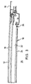
- schematisch einen Längsschnitt durch ein erfindungsgemäßes Fahrzeugdach mit einem vorderen und einem hinteren Schließelement in Schließstellung;
- Fig. 2
- eine Ansicht wie Fig. 1, wobei jedoch das vordere Schließelement in einer nach hinten unter das hintere Schließelement geschobenen Stellung gezeigt ist; und
- Fig. 3
- einen Schnitt in Fahrzeugquerrichtung im seitlichen Randbereich des hinteren Schließelements, wobei sich das vordere Schließelement in der Stellung von Fig. 2 befindet.
- Fig. 1
- schematically shows a longitudinal section through an inventive vehicle roof with a front and a rear closing element in the closed position;
- Fig. 2
- a view like Figure 1, but with the front closing element is shown in a position pushed back under the rear closing element. and
- Fig. 3
- a section in the vehicle transverse direction in the lateral edge region of the rear closing element, the front closing element being in the position of FIG. 2.
Gemäß Fig. 1 umfasst ein erfindungsgemäßes Fahrzeugdach ein vorderes
Schließelement 10, welches in Schließstellung dargestellt ist, und ein dahinter
liegend angeordnetes hinteres Schließelement 12, welche im dargestellten Zustand
gemeinsam eine Dachöffnung 14 in einer festen Dachfläche 16 verschließen.
Bei dem vorderen Schließelement handelt es sich gemäß Fig. 1 um einen
Deckel aus lichtdurchlässigem Material, vorzugsweise Glas oder Kunststoff, der
mittels einer an sich bekannten und nicht dargestellten Verstellmechanik eine reine
Schiebedachfunktion oder auch eine Schiebehebedachfunktion erfüllen kann.
In beiden Fällen ist die Verstellmechanik so ausgebildet, dass der vordere Deckel
10 mittels eines an sich bekannten und nicht dargestellten Antriebs nach hinten
unter das hintere Schließelement 12 schiebbar ist, um die Dachöffnung 14 zumindest
im vorderen Bereich freizulegen. 1, a vehicle roof according to the invention comprises a front one
Das hintere Schließelement 12 ist gemäß Fig. 1 ebenfalls als Deckel aus transparentem
Material, vorzugsweise Glas oder Kunststoff, ausgebildet, wobei der hintere
Deckel 12 feststehend, d.h. nicht verstellbar, oder mit seiner Hinterkante in eine
Lüftungsposition ausstellbar gebildet sein kann.The
Unterhalb des hinteren Deckels 12 ist ein lichtdurchlässiges Festelement 18 vorgesehen,
welches fahrzeugfest montiert ist und vorzugsweise als Glas- oder
Kunststoffplatte ausgebildet ist. Hinter dem Festelement 18 schließt sich ein
Festhimmel 20 an. Das Festelement 18 umfasst gemäß Fig. 3 die Glas- oder
Kunststoffplatte 22 sowie eine an der Oberseite oder, wie in Fig. 3 gezeigt, an der
Unterseite der Platte 22 angebrachte Schicht 24, deren Transmission über eine
angelegte Spannung vom Fahrzeugnutzer einstellbar ist. Die Schicht 24 kann
dabei beispielsweise als Flüssigkristall-(LCD)-Beschichtung, SPD-(suspended
particle device)-Beschichtung oder als elektrochrome (EC) Beschichtung auf die
Platte 22 oder als entsprechende aufgeklebte Folie ausgebildet sein. Beispiele für
die Ausgestaltung der Schicht 24 mit einstellbarer Transmission sind beispielsweise
in der DE 196 30 812 A1 bzw. der DE 42 34 981 A1 beschrieben. Die
Schicht 24 dient dazu, unerwünscht starken Lichteinfall in den Fahrzeuginnenraum
26 durch den transparenten hinteren Deckel 12 und die transparente
Scheibe oder Platte 22 hindurch mittels einer entsprechenden Steuerung der
Transmission der Schicht 24 zu verhindern. Auf diese Weise kann eine Abdunklung
bzw. ein Sonnenschutz ohne zusätzliche und insbesondere bewegliche Teile,
wie beispielsweise einem Rollo oder einem Schiebehimmel, erzielt werden.A translucent
Wie in Fig. 3 gezeigt ist, ist im seitlichen Randbereich des Festelements 18 eine
Beleuchtungseinrichtung 28 vorgesehen, welche sich in Dachlängsrichtung in
zylindrischer Form erstreckt, um Licht über die seitliche Kante der Platte 22 in die
Platte 22 einzukoppeln. Die Platte 22 ist vorzugsweise so ausgebildet, dass sie
eine Vielzahl von innerhalb der Platte 22 gebildeten Reflexionsflächen aufweist,
welche das eingekoppelte Licht nach unten zum Fahrzeuginnenraum 26 hin reflektieren,
um das Festelement 18 als Lichtquelle für den Fahrzeuginnenraum 26
nutzen zu können. Eine geeignete Ausgestaltung der Scheibe oder Platte 22 des
Festelements 18 ist in der US 5 079 675 beschrieben. Details bezüglich der Ausgestaltung
der Beleuchtungseinrichtung 28 und deren Anordnung bezüglich des
Festelements 18 sind in der oben erwähnten älteren deutschen Patentanmeldung
Nr. 101 14 497.0 beschrieben. Insbesondere kann die Beleuchtungseinrichtung
28 so ausgebildet sein, dass sie eine wahlweise Beleuchtung in mindestens zwei
unterschiedlichen Farben erlaubt und die Lichtintensität einstellbar ist. Insbesondere
kann die Beleuchtungseinrichtung 28 von Leuchtdioden oder von einer
Leuchtstoffröhre bzw. Entladungsröhre gebildet sein.As shown in FIG. 3, there is one in the lateral edge region of the
Durch das Vorsehen der Beleuchtungseinrichtung 28 kann ohne besonderen zusätzlichen
Aufwand mittels des Festelements 18 eine angenehme und komfortable
zusätzliche Lichtquelle für den Fahrzeuginnenraum geschaffen werden.By providing the
In Fig. 2 und 3 ist eine Stellung des vorderen Deckels 10 dargestellt, in welcher
dieser nach hinten zwischen den hinteren Deckel 12 und das Festelement 18 geschoben
ist. Bei dieser Öffnungsbewegung des vorderen Deckels 10 nach hinten
wirkt das Festelement 18 als Schutz für einen Fondpassagier bezüglich des vorderen
Deckels 10, wobei insbesondere ein Einklemmschutz im Bereich der seitlich
unterhalb des hinteren Deckels 12 angeordneten Verstell- und Führungsmechanik
für den vorderen Deckel 10 sowie ein Einklemmschutz im Bereich der
Hinterkante des vorderen Deckels 10 bzw. im Bereich einer dort vorgesehenen
Wasserrinne (nicht gezeigt) realisiert werden kann.2 and 3, a position of the
Durch die geschilderte Ausgestaltung des Festelements 18 kann auf einfache
Weise ein Einklemmschutz ohne wesentliche Beeinträchtigung des durch die
transparente Ausgestaltung des vorderen Deckels 10 und des hinteren Deckels
12 erzielten optischen Eindrucks erreicht werden, wobei gleichzeitig das Festelement
18 mittels seiner Abdunklungsfunktion und seiner Beleuchtungsfunktion als
komfortsteigerndes Element für die Fahrzeuginsassen wirkt. Due to the described design of the
Vorzugsweise ist das Festelement 18 mit Lüftungsöffnungen (nicht gezeigt) versehen,
um einen Luftaustausch zwischen dem Fahrzeuginnenraum 26 und dem
oberhalb des Festelements 18 gelegenen Raum zu ermöglichen, was vor allem
bei ausgestelltem vorderen bzw. ausgestelltem hinteren Deckel 10 bzw. 12 vorteilhaft
ist. The
- 1010
- vorderer Deckelfront cover
- 1212
- hinterer Deckelrear cover
- 1414
- Dachöffnungroof opening
- 1616
- feste Dachflächesolid roof area
- 1818
- Festelementfixed element
- 2020
- Festhimmelhard sky
- 2222
- Platte von 18Plate from 18th
- 2424
- Schicht auf 22Shift on 22nd
- 2626
- FahrzeuginnenraumVehicle interior
- 2828
- Beleuchtungseinrichtunglighting device
Claims (11)
dadurch gekennzeichnet, dass unterhalb des hinteren Schließelements (12) ein mindestens zum Teil transparentes Festelement (18) angeordnet ist und
dass das vordere Schließelement (10) in seiner nach hinten unter das hintere Schließelement (12) geschobenen Stellung zwischen dem Festelement (18) und dem hinteren Schließelement (12) liegt.Openable vehicle roof with an at least partially transparent front closing element (10) and an at least partially transparent rear closing element (12) behind it in the direction of travel for closing a roof opening (14), the front closing element (10) to the rear under the rear Closing element (12) can be pushed in order to at least partially expose the roof opening (14),
characterized in that an at least partially transparent fixed element (18) is arranged below the rear closing element (12) and
that the front closing element (10) in its position pushed backwards under the rear closing element (12) lies between the fixed element (18) and the rear closing element (12).
dadurch gekennzeichnet, dass das hintere Schließelement (12), das insbesondere ein Glas- oder Kunststoffdeckel ist, feststehend ausgebildet ist.Vehicle roof according to claim 1,
characterized in that the rear closing element (12), which is in particular a glass or plastic cover, is designed to be stationary.
dadurch gekennzeichnet, dass das hintere Schließelement (12) ein mit seiner Hinterkante in eine Lüftungsposition ausstellbarer Deckel (12) ist.Vehicle roof according to claim 1 or 2,
characterized in that the rear closing element (12) is a cover (12) which can be extended with its rear edge into a ventilation position.
dadurch gekennzeichnet, dass das Festelement (18) eine Schicht (24) aufweist, deren Transmission vom Fahrzeugnutzer einstellbar ist. Vehicle roof according to one of the preceding claims,
characterized in that the fixed element (18) has a layer (24) whose transmission can be adjusted by the vehicle user.
dadurch gekennzeichnet, dass die Schicht (24) als LCD-, EC- oder SPD-Beschichtung oder als aufgeklebte LCD-, EC- oder SPD-Folie ausgebildet ist.Vehicle roof according to claim 4,
characterized in that the layer (24) is designed as an LCD, EC or SPD coating or as a glued-on LCD, EC or SPD film.
dadurch gekennzeichnet, dass das Festelement (18) als Glas- oder Kunststoffplatte (22) ausgebildet ist.Vehicle roof according to one of the preceding claims,
characterized in that the fixed element (18) is designed as a glass or plastic plate (22).
dadurch gekennzeichnet, dass eine Beleuchtungseinrichtung (28) zur Beleuchtung des Festelements (18) vorgesehen ist, um das Festelement (18) wahlweise als Lichtquelle für den Fahrzeuginnenraum (26) zu nutzen.Vehicle roof according to one of the preceding claims,
characterized in that an illumination device (28) is provided for illuminating the fixed element (18) in order to selectively use the fixed element (18) as a light source for the vehicle interior (26).
dadurch gekennzeichnet, dass die Beleuchtungseinrichtung (28) nahe des hinteren und/oder eines seitlichen Endes des Festelements (18) vorgesehen ist, um Beleuchtungslicht über die Hinterkante bzw. die Seitenkante des Festelements (18) in das Festelement (18) einzukoppeln.Vehicle roof according to claim 7,
characterized in that the lighting device (28) is provided near the rear and / or a lateral end of the fixed element (18) in order to couple illuminating light into the fixed element (18) via the rear edge or the side edge of the fixed element (18).
dadurch gekennzeichnet, dass die Beleuchtungseinrichtung (28) zylindrisch oder sphärisch ausgebildet ist.Vehicle roof according to claim 8,
characterized in that the lighting device (28) is cylindrical or spherical.
dadurch gekennzeichnet, dass die Beleuchtungseinrichtung (28) Leuchtdioden oder eine Leuchtstoffröhre umfasst.Vehicle roof according to one of claims 7 to 9,
characterized in that the lighting device (28) comprises light emitting diodes or a fluorescent tube.
dadurch gekennzeichnet, dass das Festelement (18) mit Lüftungsöffnungen versehen ist, um einen Luftaustausch zwischen dem Fahrzeuginnenraum (26) und dem oberhalb des Festelements (18) gelegenen Raum bei geöffnetem vorderen Schließelement (10) und/oder geöffnetem hinteren Schließelement (12) zu ermöglichen.Vehicle roof according to one of the preceding claims,
characterized in that the fixed element (18) is provided with ventilation openings in order to exchange air between the vehicle interior (26) and the space located above the fixed element (18) when the front closing element (10) and / or the rear closing element (12) is open enable.
Applications Claiming Priority (2)
| Application Number | Priority Date | Filing Date | Title |
|---|---|---|---|
| DE10130267A DE10130267A1 (en) | 2001-06-26 | 2001-06-26 | Motor vehicle sun roof with front and rear sections of which only front section retracts |
| DE10130267 | 2001-06-26 |
Publications (2)
| Publication Number | Publication Date |
|---|---|
| EP1288042A1 true EP1288042A1 (en) | 2003-03-05 |
| EP1288042B1 EP1288042B1 (en) | 2004-08-11 |
Family
ID=7689156
Family Applications (1)
| Application Number | Title | Priority Date | Filing Date |
|---|---|---|---|
| EP02013115A Expired - Lifetime EP1288042B1 (en) | 2001-06-26 | 2002-06-14 | Openable vehicle roof with a movable front and rear closing element |
Country Status (2)
| Country | Link |
|---|---|
| EP (1) | EP1288042B1 (en) |
| DE (2) | DE10130267A1 (en) |
Families Citing this family (4)
| Publication number | Priority date | Publication date | Assignee | Title |
|---|---|---|---|---|
| US7832784B2 (en) | 2003-12-19 | 2010-11-16 | Ferrari Spa | Motor vehicle provided with a folding top |
| ITBO20040465A1 (en) | 2004-07-23 | 2004-10-23 | Ferrari Spa | CAR FRAME EQUIPPED WITH MODULES IN COMPOSITE MATERIAL PRODUCED WITH RTM TECHNOLOGY |
| DE102004042416A1 (en) * | 2004-09-02 | 2006-03-09 | Bayerische Motoren Werke Ag | Sliding/lifting roof with two covers for vehicle has front cover that is arranged partly under rear cover and partly under fixed roof part behind rear cover in its roof opening position |
| DE102005015602A1 (en) * | 2005-04-05 | 2006-10-12 | Webasto Ag | Shadow arrangement for a translucent vehicle body surface |
Citations (2)
| Publication number | Priority date | Publication date | Assignee | Title |
|---|---|---|---|---|
| US5951100A (en) * | 1994-07-05 | 1999-09-14 | Asc Incorporated | Sunroof assembly for an automotive vehicle |
| US6129413A (en) * | 1997-11-13 | 2000-10-10 | Asc Incorporated | Powered dual panel sunroof |
Family Cites Families (5)
| Publication number | Priority date | Publication date | Assignee | Title |
|---|---|---|---|---|
| DE713106C (en) * | 1938-11-04 | 1941-10-31 | Carl F W Borgward | Sunroof for motor vehicles |
| DE1141901B (en) * | 1956-12-28 | 1962-12-27 | Karosseriewerke Weinsberg G M | Rigid sunroof, especially for motor vehicles |
| DE4335653A1 (en) * | 1993-10-15 | 1995-04-20 | Porsche Ag | Body for passenger cars |
| DE19902244A1 (en) * | 1999-01-21 | 2000-08-03 | Daimler Chrysler Ag | Headlining with a transparent roof element |
| DE19907377B4 (en) * | 1999-02-20 | 2014-09-11 | Bayerische Motoren Werke Aktiengesellschaft | Sliding roof of a passenger car with in particular two cover parts |
-
2001
- 2001-06-26 DE DE10130267A patent/DE10130267A1/en not_active Withdrawn
-
2002
- 2002-06-14 DE DE50200791T patent/DE50200791D1/en not_active Expired - Fee Related
- 2002-06-14 EP EP02013115A patent/EP1288042B1/en not_active Expired - Lifetime
Patent Citations (2)
| Publication number | Priority date | Publication date | Assignee | Title |
|---|---|---|---|---|
| US5951100A (en) * | 1994-07-05 | 1999-09-14 | Asc Incorporated | Sunroof assembly for an automotive vehicle |
| US6129413A (en) * | 1997-11-13 | 2000-10-10 | Asc Incorporated | Powered dual panel sunroof |
Also Published As
| Publication number | Publication date |
|---|---|
| EP1288042B1 (en) | 2004-08-11 |
| DE50200791D1 (en) | 2004-09-16 |
| DE10130267A1 (en) | 2003-01-09 |
Similar Documents
| Publication | Publication Date | Title |
|---|---|---|
| DE10204359B4 (en) | vehicle roof | |
| DE19706043A1 (en) | Plastic window for motor vehicle door | |
| DE102009049114B4 (en) | Vehicle with transparent roof area | |
| DE60312625T2 (en) | Sun visor for vehicles | |
| EP1300271A1 (en) | Roof structure for a motor vehicle | |
| DE19914427A1 (en) | Motor vehicle roof has fixed roof section, transversely sliding roof parts, all of which have transparent areas; sliding parts can be moved sideways to parallel positions beneath fixed parts | |
| DE19701211C1 (en) | Sunroof fitted to motor vehicle | |
| DE19849840C1 (en) | Automobile transparent sunroof has sliding and stationary sunroof sections with non-transparent area of one or both provided with solar cells | |
| EP0619198B1 (en) | Vehicle roof with glass panel and sun visor | |
| DE3222861C2 (en) | Anti-glare device for vehicles equipped with a retractable side window | |
| EP1288042B1 (en) | Openable vehicle roof with a movable front and rear closing element | |
| DE10019677B4 (en) | Vehicle roof with a roof opening and two lids | |
| EP1393945A2 (en) | Vehicle roof with a closing panel being slidable in a rear direction | |
| DE102019004298B4 (en) | Lighting unit and vehicle | |
| DE19538551C1 (en) | Sun screen for motor vehicle sun-roof | |
| DE1019574B (en) | Wind deflector for sunroof sedans or similar vehicles | |
| DE602004010766T2 (en) | Ambient lighting system for motor vehicles, lighting device, vehicle and roller blind with such a system | |
| DE10109008C2 (en) | Vehicle roof with lighting element | |
| DE10245901A1 (en) | Roller blind arrangement for vehicle screens has winding movable between standby position at edge of screen, stowed position in which shaft with rewound blind is outside viewing area through screen | |
| DE10063056A1 (en) | Winding type sun shade device for sunroof apparatus of e.g. motor vehicle, has tensile force control device which makes tensile force of sheet adjustable and includes brackets and shape retaining component | |
| DE69012688T2 (en) | Sunroof for a motor vehicle. | |
| DE102004063515A1 (en) | Motor vehicle e.g. cabriolet vehicle, unit e.g. sliding door, has guiding unit formed as single-piece in window pane to guide adjustable component with adjustable movement relative to pane | |
| DE102011013320A1 (en) | Motor vehicle e.g. passenger car has sun visor elements that are arranged in primary vision region and secondary vision region so as to darken primary vision region and secondary vision region | |
| DE19914118B4 (en) | Awning roof with a roof cover and an associated hatch for a motor vehicle | |
| DE4205495C1 (en) | Sun visor for automobiles - has tilting body with mounted vanity mirror, and additional transparent micro-lamellar visor slidably stored behind first to allow light to pass through it w.r.t. its inclination |
Legal Events
| Date | Code | Title | Description |
|---|---|---|---|
| PUAI | Public reference made under article 153(3) epc to a published international application that has entered the european phase |
Free format text: ORIGINAL CODE: 0009012 |
|
| AK | Designated contracting states |
Designated state(s): AT BE CH CY DE DK ES FI FR GB GR IE IT LI LU MC NL PT SE TR Kind code of ref document: A1 Designated state(s): AT BE CH CY DE DK ES FI FR GB GR IE IT LI LU MC NL PT SE TR |
|
| AX | Request for extension of the european patent |
Extension state: AL LT LV MK RO SI |
|
| 17P | Request for examination filed |
Effective date: 20030828 |
|
| GRAP | Despatch of communication of intention to grant a patent |
Free format text: ORIGINAL CODE: EPIDOSNIGR1 |
|
| AKX | Designation fees paid |
Designated state(s): DE FR GB NL |
|
| GRAS | Grant fee paid |
Free format text: ORIGINAL CODE: EPIDOSNIGR3 |
|
| GRAA | (expected) grant |
Free format text: ORIGINAL CODE: 0009210 |
|
| AK | Designated contracting states |
Kind code of ref document: B1 Designated state(s): DE FR GB NL |
|
| REG | Reference to a national code |
Ref country code: GB Ref legal event code: FG4D Free format text: NOT ENGLISH |
|
| REG | Reference to a national code |
Ref country code: IE Ref legal event code: FG4D Free format text: GERMAN |
|
| REF | Corresponds to: |
Ref document number: 50200791 Country of ref document: DE Date of ref document: 20040916 Kind code of ref document: P |
|
| GBT | Gb: translation of ep patent filed (gb section 77(6)(a)/1977) |
Effective date: 20040908 |
|
| REG | Reference to a national code |
Ref country code: IE Ref legal event code: FD4D |
|
| PLBE | No opposition filed within time limit |
Free format text: ORIGINAL CODE: 0009261 |
|
| STAA | Information on the status of an ep patent application or granted ep patent |
Free format text: STATUS: NO OPPOSITION FILED WITHIN TIME LIMIT |
|
| ET | Fr: translation filed | ||
| 26N | No opposition filed |
Effective date: 20050512 |
|
| REG | Reference to a national code |
Ref country code: FR Ref legal event code: TP |
|
| PGFP | Annual fee paid to national office [announced via postgrant information from national office to epo] |
Ref country code: NL Payment date: 20080603 Year of fee payment: 7 |
|
| PGFP | Annual fee paid to national office [announced via postgrant information from national office to epo] |
Ref country code: FR Payment date: 20080617 Year of fee payment: 7 |
|
| PGFP | Annual fee paid to national office [announced via postgrant information from national office to epo] |
Ref country code: GB Payment date: 20080618 Year of fee payment: 7 |
|
| PGFP | Annual fee paid to national office [announced via postgrant information from national office to epo] |
Ref country code: DE Payment date: 20090615 Year of fee payment: 8 |
|
| GBPC | Gb: european patent ceased through non-payment of renewal fee |
Effective date: 20090614 |
|
| NLV4 | Nl: lapsed or anulled due to non-payment of the annual fee |
Effective date: 20100101 |
|
| REG | Reference to a national code |
Ref country code: FR Ref legal event code: ST Effective date: 20100226 |
|
| PG25 | Lapsed in a contracting state [announced via postgrant information from national office to epo] |
Ref country code: FR Free format text: LAPSE BECAUSE OF NON-PAYMENT OF DUE FEES Effective date: 20090630 |
|
| PG25 | Lapsed in a contracting state [announced via postgrant information from national office to epo] |
Ref country code: GB Free format text: LAPSE BECAUSE OF NON-PAYMENT OF DUE FEES Effective date: 20090614 |
|
| PG25 | Lapsed in a contracting state [announced via postgrant information from national office to epo] |
Ref country code: NL Free format text: LAPSE BECAUSE OF NON-PAYMENT OF DUE FEES Effective date: 20100101 |
|
| PG25 | Lapsed in a contracting state [announced via postgrant information from national office to epo] |
Ref country code: DE Free format text: LAPSE BECAUSE OF NON-PAYMENT OF DUE FEES Effective date: 20110101 |