EP1287878A2 - Apparatus fot treatment of materials - Google Patents
Apparatus fot treatment of materials Download PDFInfo
- Publication number
- EP1287878A2 EP1287878A2 EP02018534A EP02018534A EP1287878A2 EP 1287878 A2 EP1287878 A2 EP 1287878A2 EP 02018534 A EP02018534 A EP 02018534A EP 02018534 A EP02018534 A EP 02018534A EP 1287878 A2 EP1287878 A2 EP 1287878A2
- Authority
- EP
- European Patent Office
- Prior art keywords
- rotor
- container
- insert
- carrier
- stator
- Prior art date
- Legal status (The legal status is an assumption and is not a legal conclusion. Google has not performed a legal analysis and makes no representation as to the accuracy of the status listed.)
- Granted
Links
- 239000000463 material Substances 0.000 title claims abstract description 16
- 238000003825 pressing Methods 0.000 claims abstract description 6
- 238000012545 processing Methods 0.000 claims abstract description 5
- 238000000227 grinding Methods 0.000 claims description 3
- 238000004898 kneading Methods 0.000 claims description 3
- 206010061592 cardiac fibrillation Diseases 0.000 claims description 2
- 230000029087 digestion Effects 0.000 claims description 2
- 230000002600 fibrillogenic effect Effects 0.000 claims description 2
- 230000002441 reversible effect Effects 0.000 claims description 2
- 230000035515 penetration Effects 0.000 claims 1
- 239000000047 product Substances 0.000 description 9
- 230000007704 transition Effects 0.000 description 7
- 239000007788 liquid Substances 0.000 description 4
- 229910000831 Steel Inorganic materials 0.000 description 3
- 238000004140 cleaning Methods 0.000 description 3
- 238000012423 maintenance Methods 0.000 description 3
- NJPPVKZQTLUDBO-UHFFFAOYSA-N novaluron Chemical compound C1=C(Cl)C(OC(F)(F)C(OC(F)(F)F)F)=CC=C1NC(=O)NC(=O)C1=C(F)C=CC=C1F NJPPVKZQTLUDBO-UHFFFAOYSA-N 0.000 description 3
- 239000010959 steel Substances 0.000 description 3
- 230000004888 barrier function Effects 0.000 description 2
- 238000005452 bending Methods 0.000 description 2
- 230000000903 blocking effect Effects 0.000 description 2
- 229910052751 metal Inorganic materials 0.000 description 2
- 239000002184 metal Substances 0.000 description 2
- 238000007789 sealing Methods 0.000 description 2
- 241001310793 Podium Species 0.000 description 1
- 229920000297 Rayon Polymers 0.000 description 1
- 206010062544 Tooth fracture Diseases 0.000 description 1
- 239000000654 additive Substances 0.000 description 1
- 230000008901 benefit Effects 0.000 description 1
- 239000000872 buffer Substances 0.000 description 1
- 239000006227 byproduct Substances 0.000 description 1
- 230000008859 change Effects 0.000 description 1
- 239000012611 container material Substances 0.000 description 1
- 230000007423 decrease Effects 0.000 description 1
- 230000002950 deficient Effects 0.000 description 1
- 238000013461 design Methods 0.000 description 1
- 230000000694 effects Effects 0.000 description 1
- 239000012530 fluid Substances 0.000 description 1
- 230000017525 heat dissipation Effects 0.000 description 1
- 239000011346 highly viscous material Substances 0.000 description 1
- 238000009776 industrial production Methods 0.000 description 1
- 238000000034 method Methods 0.000 description 1
- 230000002093 peripheral effect Effects 0.000 description 1
- 230000008569 process Effects 0.000 description 1
- 230000008439 repair process Effects 0.000 description 1
- 238000010008 shearing Methods 0.000 description 1
- 229910001220 stainless steel Inorganic materials 0.000 description 1
- 239000010935 stainless steel Substances 0.000 description 1
- 238000012546 transfer Methods 0.000 description 1
- UONOETXJSWQNOL-UHFFFAOYSA-N tungsten carbide Chemical compound [W+]#[C-] UONOETXJSWQNOL-UHFFFAOYSA-N 0.000 description 1
- 238000001238 wet grinding Methods 0.000 description 1
Images


Classifications
-
- B—PERFORMING OPERATIONS; TRANSPORTING
- B01—PHYSICAL OR CHEMICAL PROCESSES OR APPARATUS IN GENERAL
- B01F—MIXING, e.g. DISSOLVING, EMULSIFYING OR DISPERSING
- B01F27/00—Mixers with rotary stirring devices in fixed receptacles; Kneaders
- B01F27/27—Mixers with stator-rotor systems, e.g. with intermeshing teeth or cylinders or having orifices
- B01F27/272—Mixers with stator-rotor systems, e.g. with intermeshing teeth or cylinders or having orifices with means for moving the materials to be mixed axially between the surfaces of the rotor and the stator, e.g. the stator rotor system formed by conical or cylindrical surfaces
- B01F27/2723—Mixers with stator-rotor systems, e.g. with intermeshing teeth or cylinders or having orifices with means for moving the materials to be mixed axially between the surfaces of the rotor and the stator, e.g. the stator rotor system formed by conical or cylindrical surfaces the surfaces having a conical shape
-
- B—PERFORMING OPERATIONS; TRANSPORTING
- B01—PHYSICAL OR CHEMICAL PROCESSES OR APPARATUS IN GENERAL
- B01F—MIXING, e.g. DISSOLVING, EMULSIFYING OR DISPERSING
- B01F27/00—Mixers with rotary stirring devices in fixed receptacles; Kneaders
- B01F27/80—Mixers with rotary stirring devices in fixed receptacles; Kneaders with stirrers rotating about a substantially vertical axis
- B01F27/805—Mixers with rotary stirring devices in fixed receptacles; Kneaders with stirrers rotating about a substantially vertical axis wherein the stirrers or the receptacles are moved in order to bring them into operative position; Means for fixing the receptacle
-
- B—PERFORMING OPERATIONS; TRANSPORTING
- B01—PHYSICAL OR CHEMICAL PROCESSES OR APPARATUS IN GENERAL
- B01F—MIXING, e.g. DISSOLVING, EMULSIFYING OR DISPERSING
- B01F35/00—Accessories for mixers; Auxiliary operations or auxiliary devices; Parts or details of general application
- B01F35/10—Maintenance of mixers
-
- B—PERFORMING OPERATIONS; TRANSPORTING
- B01—PHYSICAL OR CHEMICAL PROCESSES OR APPARATUS IN GENERAL
- B01F—MIXING, e.g. DISSOLVING, EMULSIFYING OR DISPERSING
- B01F35/00—Accessories for mixers; Auxiliary operations or auxiliary devices; Parts or details of general application
- B01F35/71—Feed mechanisms
- B01F35/717—Feed mechanisms characterised by the means for feeding the components to the mixer
- B01F35/7173—Feed mechanisms characterised by the means for feeding the components to the mixer using gravity, e.g. from a hopper
- B01F35/71731—Feed mechanisms characterised by the means for feeding the components to the mixer using gravity, e.g. from a hopper using a hopper
-
- D—TEXTILES; PAPER
- D21—PAPER-MAKING; PRODUCTION OF CELLULOSE
- D21D—TREATMENT OF THE MATERIALS BEFORE PASSING TO THE PAPER-MAKING MACHINE
- D21D1/00—Methods of beating or refining; Beaters of the Hollander type
- D21D1/004—Methods of beating or refining including disperging or deflaking
- D21D1/006—Disc mills
-
- B—PERFORMING OPERATIONS; TRANSPORTING
- B01—PHYSICAL OR CHEMICAL PROCESSES OR APPARATUS IN GENERAL
- B01F—MIXING, e.g. DISSOLVING, EMULSIFYING OR DISPERSING
- B01F27/00—Mixers with rotary stirring devices in fixed receptacles; Kneaders
- B01F27/05—Stirrers
- B01F27/051—Stirrers characterised by their elements, materials or mechanical properties
- B01F27/053—Stirrers characterised by their elements, materials or mechanical properties characterised by their materials
- B01F27/0531—Stirrers characterised by their elements, materials or mechanical properties characterised by their materials with particular surface characteristics, e.g. coated or rough
-
- B—PERFORMING OPERATIONS; TRANSPORTING
- B01—PHYSICAL OR CHEMICAL PROCESSES OR APPARATUS IN GENERAL
- B01F—MIXING, e.g. DISSOLVING, EMULSIFYING OR DISPERSING
- B01F27/00—Mixers with rotary stirring devices in fixed receptacles; Kneaders
- B01F27/27—Mixers with stator-rotor systems, e.g. with intermeshing teeth or cylinders or having orifices
- B01F27/272—Mixers with stator-rotor systems, e.g. with intermeshing teeth or cylinders or having orifices with means for moving the materials to be mixed axially between the surfaces of the rotor and the stator, e.g. the stator rotor system formed by conical or cylindrical surfaces
- B01F27/2721—Mixers with stator-rotor systems, e.g. with intermeshing teeth or cylinders or having orifices with means for moving the materials to be mixed axially between the surfaces of the rotor and the stator, e.g. the stator rotor system formed by conical or cylindrical surfaces provided with intermeshing elements
Definitions
- the invention relates to a device for processing materials, especially for mixing, kneading, fibrillating, grinding and unlocking, with a container containing a vertical Container chamber with a product inlet located above, a stator arranged around a vertical axis concentric sprockets and a rotor with multiple arms, have the teeth which are adjacent between the teeth Sprockets grip.
- the rotor arm and the container space located above the standing arranged Device enable a permanent material transfer of inside out and ensure a multiple working through dry and / or highly viscous substances, so that the device for intensive mixing, kneading, fibrillation, digestion and Similar processes important for industrial production is outstanding.
- the standing arrangement of the housing facilitates the falling back of the goods from the periphery against the middle of the device.
- the invention is based on the object, a device of mentioned type in the sense of improving the product further education.
- the solution of this object is achieved according to the invention in the Claim 1 specified characteristics.
- a guide whose centric Funnel opening has a smaller diameter than the Rotor.
- the funnel directs this from the top to the stator / rotor funnel moving material to the center of the container and thus keeps the good in the effective range of the tools. It also ensures that the goods near the axis in the Effective range of tools reaches where it is on the inner cone of the Stators working through the teeth of stator and rotor is moved outwards.
- the hopper guides the product so in the region close to the axis of the device in the effective range of Device.
- the funnel opening extends in the vertical direction into the rotor, that is to say in that area, that of the rotor arms is circumscribed. This means that the inner Opening of the funnel is lower than the upper edges of the Arms of the rotor.
- the hopper has an outer surface, the less is steep than the inner surface.
- the outer surface or lower surface of the funnel causes in cooperation with the Internal taper surface of the stator forming an annulus, in which stagnates the outward-pressing product. In connection This product congestion is followed by product expansion due to the then increasing diameter.
- Such a design of the umpire promotes the redistribution and mixing of the Material in the effective range of the tools.
- a preferred embodiment of the invention provides that the Rotor has a towering from a hub stub shaft, which carries a feed screw.
- the feed screw promotes that Product on its way from top to bottom and generates one additional pressure in the central area of the container.
- the feed screw is particularly suitable for processing difficult-flowing Products and tougher pastes.
- the diameter of the feed screw should be expediently slightly larger than that Diameter of the funnel opening.
- the device according to the invention is also suitable for wet milling of materials. Made by the cooperating sprockets a Vorenergyeintrag in the introduced from above into the container Material with simultaneous heat dissipation through the Casing.
- the Container with a bottom wall finished, in which a Recording for a the carrier wheels supporting the sprockets Stators is located.
- the carrier insert is removable in the receptacle arranged.
- the carrier insert for the purpose of cleaning or maintenance can the carrier insert in its entirety towards the container interior be removed from the bottom wall, after previously the rotor was removed.
- the stator can then be dismantled and it is available for cleaning, overhaul or maintenance. It is not necessary to disassemble the entire container. Rather, the container must only be opened, to gain access to the tray. this happens by removing a lid of the container.
- the bottom wall is integral part of the container and does not need to be removed too become.
- stator with carrier insert and sprockets to replace and replace with a new stator, For example, if the sprockets worn or damaged are.
- the sprockets on the carrier insert can be removed be attached, with each individual ring gear of the stator can be removed from the carrier body and replaced.
- each arm of the rotor from a carrier strip and a so Matching toothed rack made of carbide.
- the carrier strip and the rack grasp fit, i. a form fit, into each other, either the carrier strip or the Rack the encompassing part and the other component represents the inner part of the Caribbeangriffs.
- carbide is a brittle Material that has low resistance to tensile stresses and has bending stresses.
- By the invention is achieved that in the rack no major tensile or bending stresses occur. Such stresses occur only in the carrier strip on, which consist of a steel of high tensile strength can.
- the device comprises a container 10, for example has a diameter of 600 mm and standing upright a column 100 is mounted.
- the column is 100 mounted on a pedestal 101, which with bearing blocks 102 on standing on the ground.
- podium 101 On podium 101 are two electric motors 103, 104 mounted with vertical axes. Every electric motor drives a pulley 105, 106 inside the pedestal 101 is arranged.
- the pulleys 105, 106 over drive Drive belt 107, 108 a pulley 109, with the in the Column 100 mounted shaft of the device is connected.
- the container 10 has an upper container part 110 which abuts is closed at its upper end with a lid 111. At the lower end of the container part 110 includes a in Side view trapezoidal transition wall 15 at, in a Bottom wall 11 opens. Below the bottom wall is a Blocking liquid housing 112 to which a supply line and a discharge line for barrier liquid is connected.
- the Barrier liquid housing 112 is supported by column 100.
- the container 10 is supported by vertical posts 113, whose lower ends are fixed on the pedestal 101 and the at wear rubber bumper 114 at its upper end.
- the container part 110 has a rectangular - or square - plan. Corner regions 120 are formed, which are rounded and each have an angle of 90 degrees, and straight edge portions 121 that the Connect corner areas.
- the container part 110 is with the truncated pyramid-shaped lower part 130 detachably connected via a flange 131.
- power clamp 132 To the Holding the flange connection 131 are power clamp 132, which can be opened to dismantle the container.
- an overflow 134 is provided on the lower part 130 .
- the container lid 111 On the container lid 111 is centrally located a product inlet 136, through which the product to be processed vertically in the container 10 is input. There are also other inlet ports 137 provided filled by the additives can be. Finally, the lid 111 is still a show opening 135 attached. An access opening is with an in Cover 111 arranged door 138 closed (Fig. 2).
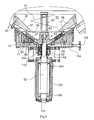
- Fig. 3 the column 100 is passing through it Shaft 12 shown.
- the shaft is with bearings 150, 151 in the Pillar 100 stored.
- the passage of the shaft 12 through the bottom wall 11 is sealed by a seal 22.
- the seal 22 has an inlet 152 and an outlet 153 for sealing fluid on.
- a channel 154 extends to a terminal 155 for the emptying. Through the channel 154 becomes liquid, which is the lowest point of the container space 50 drops, discharged from the container space.
- the bottom wall 11 a circumferential upstanding edge 14 on which the oblique transition wall 15 of the container 10 is attached.
- the Bottom wall 11 defines together with its edge 14 an annular Recording 16, in which an annular stator 17 is arranged is.
- the stator 17 has an inner cone or inner pyramid trained work surface 18.
- Half the ring cross-section of the Stator 17 is generally in the shape of a right triangle, wherein the working surface 18 forms the hypotenuse.
- the stator 17 consists of an annular support insert 19, fitting in the receptacle 16 is included, and several along the work surface 18 arranged sprockets 20th to the inside the receptacle 16 is bounded by an inner ring insert 21, the sealed with the seal 22 shaft passage the shaft 12 forms.
- the carrier insert 19 At the outer periphery is the carrier insert 19 with an annular seal 23 against the peripheral wall the receptacle 16 sealed.
- the Carrier insert with two annular seals 24, 24 'and 25 against the receptacle 16 inwardly bounding inner ring insert 21 sealed. This will prevent that the mass to be treated penetrates behind the carrier insert 19.
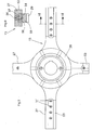
- the rotor 13 has a shaft 26 mounted on the hub 26 and a plurality of radially projecting arms 27 on.
- the arms 27 carry downwardly directed teeth 29, which with teeth 28 of the sprockets 20 of the stator.
- the teeth 28 are from each of the sprockets 20 upwards.
- the teeth 29 of the rotor 13 engage in the tooth spaces between the sprockets 20 of the Stators 17. In the circumferential direction are the teeth 28 of each Sprocket 20 spaced.
- the teeth 28 and 29 are made of wear-resistant material, in particular of hard metal.
- each arm 27 of the rotor 13 a carrier strip 53 of generally U-shaped cross section.
- the carrier strip 53 includes on its oblique bottom a longitudinal groove 54 of rectangular cross-section, in which a Rack 55 is sitting.
- the carrier strip 53 is made of high-strength Steel, while the rack 55 is made of hard metal. Of the Back of the rack 55 fills the groove 54 completely with closer Fit.
- the teeth 29 are located at the out of the groove 54th outstanding part of the rack 55.
- the rack 55 is fixed with screws 56, the through holes 57 of the support bar 53 inserted therethrough are and their threads in a threaded insert 58, which in the Rack 55 is sunk, are screwed.
- the threaded insert 58 is made of steel and is soldered into the rack 55. By loosening the screws 56, evenly spaced are provided along an arm 27, the Rack 55 are dismantled.
- the outermost ring 30a which the adjacent inner support ring 30th holds, is made of stainless steel and is formed without teeth. He is held by a screw on the carrier insert 19. The outer ring 30a thus forms the blocking element for all carrier rings 30.
- the carrier insert 19 can be removed from the receptacle 16 become. This is done by (not shown) pressing screws, screwed into threaded holes 60 of the bottom wall 11 and against the underside of the carrier insert 19 to press. Overall, for example, four threaded holes 60th arranged evenly distributed in the bottom wall 11 for pressing screws. By turning the push-in screws evenly the carrier insert 19 is pushed up into the container space 50. Before this happens, of course, the rotor 13 must be removed. This is done by loosening the screw 61, the rotor 13th on the shaft 12 holds. To gain access to the screw 61, is the plug 41 from the stub shaft 40th unscrewed.
- each individual ring gear 20 can be detached from the carrier insert 19 become.
- each ring gear 20 is inside the carrier insert a threaded bore 68 assigned (Fig. 3), in the a push-in screw sits.
- the push screws are from the bottom the carrier insert 19 is accessible for turning and they can be turned to the respective sprocket 20 off to push out the relevant recess of the carrier insert 19. It is thus possible, each of the sprockets 20 individually replaced.
- Serve screws 70 through the bottom wall 11 therethrough are screwed into the carrier insert 19.
- the retaining screws 70 can be loosened.
- a hopper 34 is at a distance mounted by the transition wall 15.
- the hopper 34 has a funnel-shaped inner surface 35, which in a funnel opening 36 opens at the lower end of the funnel.
- the funnel opening 36 projects into the limited by the arms 27 of the rotor Space from the top in and it has a smaller diameter as the rotor 13.
- the funnel opening 36 concentrated the stuffing from the top into the container and nach Kohlende material to the area of the hub 26, ie to the middle area. There The material enters between the arms 27 of the rotor 13 and passes in the tooth area.
- the hopper 34 has an outer surface 37, the less is steep than the inner surface 35. This has the funnel 34 an increasing diameter with increasing diameter.
- the Outer surface 37 forms together with the transition surface 33 a Annular gap 38 in extension of the arms 27 of the rotor 13.
- the Height of the annular gap 38 decreases towards the outside.
- the hub 26 is in extension of the shaft 12 with a towering Stub shaft 40 provided, which is tubular and with a closure 41 is closed.
- the stub shaft 40 carries a feed screw 42 of one to two courses.
- the feed screw promotes upon rotation of the driven shaft 12 in Direction from top to bottom, so the hub 26 out.
- the diameter the feed screw 42 is slightly larger than the diameter the funnel opening 36.
- the feed screw 42 generates a increased pressure in the center, ie around the rotor 13 around.
Landscapes
- Chemical & Material Sciences (AREA)
- Chemical Kinetics & Catalysis (AREA)
- Mixers Of The Rotary Stirring Type (AREA)
- Filling Or Emptying Of Bunkers, Hoppers, And Tanks (AREA)
- Electrical Discharge Machining, Electrochemical Machining, And Combined Machining (AREA)
- Threshing Machine Elements (AREA)
- Crushing And Pulverization Processes (AREA)
- Disintegrating Or Milling (AREA)
Abstract
Description
Die Erfindung betrifft eine Vorrichtung zur Bearbeitung von Materialien, insbesondere zum Mischen, Kneten, Fibrillieren, Mahlen und Aufschließen, mit einem Behälter, der einen vertikalen Behälterraum mit einem oben angeordneten Produkteinlaß umschließt, einem Stator mit um eine vertikale Achse angeordneten konzentrischen Zahnkränzen und einem Rotor mit mehreren Armen, die Zähne aufweisen, welche zwischen die Zähne benachbarter Zahnkränze greifen.The invention relates to a device for processing materials, especially for mixing, kneading, fibrillating, grinding and unlocking, with a container containing a vertical Container chamber with a product inlet located above, a stator arranged around a vertical axis concentric sprockets and a rotor with multiple arms, have the teeth which are adjacent between the teeth Sprockets grip.
DE 36 41 413 C1 beschreibt eine Vorrichtung zur Bearbeitung von Materialien, die mit einem als Innenkegel ausgebildeten; mit Zahnkränzen ausgestatteten Stator versehen ist. Mit dem Stator arbeitet ein Rotor zusammen, der von einer Nabe abstehende Arme aufweist. Jeder dieser Arme trägt Zähne, die mit den Zähnen der Zahnkränze des Stators zusammengreifen. Das zu behandelnde Gut wird in dem Stator bei jeder Rotorumdrehung eine Stufe weiter nach außen transportiert und dabei einer intensiven Scherwirkung, Durchmischung und Umverteilung ausgesetzt. Der Rotorarm und der darüber befindliche Behälterraum der stehend angeordneten Vorrichtung ermöglichen eine permanente Gutumlagerung von innen nach außen und sorgen für ein vielfaches Durcharbeiten trockener und/oder hochviskoser Stoffe, so dass die Vorrichtung zum intensiven Mischen, Kneten, Fibrillieren, Aufschließen und ähnlichen für die industrielle Produktion wichtigen Vorgängen hervorragend geeignet ist. Die stehende Anordnung des Gehäuses erleichtert das Zurückfallen des Gutes von der Peripherie gegen die Mitte der Vorrichtung.DE 36 41 413 C1 describes a device for processing Materials formed with an inner cone; With Sprockets equipped stator is provided. With the stator a rotor works together, the arms projecting from a hub having. Each of these arms carries teeth that with the teeth of the Gather the toothed rings of the stator. The good to be treated becomes one stage in the stator at each rotor revolution transported to the outside and thereby an intense shearing, Intermixing and redistribution exposed. The rotor arm and the container space located above the standing arranged Device enable a permanent material transfer of inside out and ensure a multiple working through dry and / or highly viscous substances, so that the device for intensive mixing, kneading, fibrillation, digestion and Similar processes important for industrial production is outstanding. The standing arrangement of the housing facilitates the falling back of the goods from the periphery against the middle of the device.
Der Erfindung liegt die Aufgabe zugrunde, eine Vorrichtung der genannten Art im Sinne einer Verbesserung der Produktführung weiterzubilden.The invention is based on the object, a device of mentioned type in the sense of improving the product further education.
Die Lösung dieser Aufgabe erfolgt erfindungsgemäß mit den im Anspruch 1 angegebenen Merkmalen. Hiernach ist in dem Behälterraum über dem Rotor ein Leitrichter angeordnet, dessen zentrische Trichteröffnung einen kleineren Durchmesser hat als der Rotor. Der Leittrichter leitet das von oben her zu dem Stator/Rotor-Trichter nachrückende Material zum Zentrum des Behälters und hält somit das Gut im Wirkbereich der Werkzeuge. Außerdem wird sichergestellt, dass das Gut in Achsennähe in den Wirkbereich der Werkzeuge gelangt, wo es auf dem Innenkegel des Stators unter Bearbeitung durch die Zähne von Stator und Rotor nach außen bewegt wird. Der Leittrichter führt das Produkt also im achsnahen Bereich der Vorrichtung in den Wirkbereich der Vorrichtung ein.The solution of this object is achieved according to the invention in the Claim 1 specified characteristics. After that is in the container space arranged above the rotor, a guide, whose centric Funnel opening has a smaller diameter than the Rotor. The funnel directs this from the top to the stator / rotor funnel moving material to the center of the container and thus keeps the good in the effective range of the tools. It also ensures that the goods near the axis in the Effective range of tools reaches where it is on the inner cone of the Stators working through the teeth of stator and rotor is moved outwards. The hopper guides the product so in the region close to the axis of the device in the effective range of Device.
Vorzugsweise reicht die Trichteröffnung in vertikaler Richtung bis in den Rotor hinein, also in denjenigen Bereich, der von den Rotorarmen umstrichen wird. Dies bedeutet, dass die innere Öffnung des Leittrichters tiefer liegt als die Oberkanten der Arme des Rotors.Preferably, the funnel opening extends in the vertical direction into the rotor, that is to say in that area, that of the rotor arms is circumscribed. This means that the inner Opening of the funnel is lower than the upper edges of the Arms of the rotor.
Gemäß einer bevorzugten Ausgestaltung der Erfindung ist vorgesehen, dass der Leittrichter eine Außenfläche aufweist, die weniger steil ist als die Innenfläche. Die Außenfläche oder Unterfläche des Leittrichters bewirkt im Zusammenwirken mit der Innenkegelfläche des Stators die Bildung eines Ringraums, in dem sich das nach außen drängende Produkt staut. Im Anschluss an diesen Materialstau erfolgt eine Produktexpansion wegen des dann größer werdenden Durchmessers. Eine solche Ausgestaltung des Leittrichters fördert das Umverteilen und Durchmischen des Materials im Wirkbereich der Werkzeuge.According to a preferred embodiment of the invention is provided that the hopper has an outer surface, the less is steep than the inner surface. The outer surface or lower surface of the funnel causes in cooperation with the Internal taper surface of the stator forming an annulus, in which stagnates the outward-pressing product. In connection This product congestion is followed by product expansion due to the then increasing diameter. Such a design of the umpire promotes the redistribution and mixing of the Material in the effective range of the tools.
Eine bevorzugte Weiterbildung der Erfindung sieht vor, dass der Rotor einen von einer Nabe aufragenden Wellenstumpf aufweist, der eine Zufuhrschnecke trägt. Die Zufuhrschnecke fördert das Produkt auf seinem Weg von oben nach unten und erzeugt einen zusätzlichen Druck im Zentralbereich des Behälters. Die Zufuhrschnecke ist besonders geeignet für die Verarbeitung schwerfließender Produkte und zäher Pasten. Der Durchmesser der Zufuhrschnecke sollte zweckmäßigerweise etwas größer sein als der Durchmesser der Trichteröffnung.A preferred embodiment of the invention provides that the Rotor has a towering from a hub stub shaft, which carries a feed screw. The feed screw promotes that Product on its way from top to bottom and generates one additional pressure in the central area of the container. The feed screw is particularly suitable for processing difficult-flowing Products and tougher pastes. The diameter of the feed screw should be expediently slightly larger than that Diameter of the funnel opening.
Die erfindungsgemäße Vorrichtung eignet sich auch zum Naßmahlen von Materialien. Durch die zusammenwirkenden Zahnkränze erfolgt ein Vorenergieeintrag in das von oben in den Behälter eingebrachte Material bei gleichzeitiger Wärmeabführung durch das Gehäuse.The device according to the invention is also suitable for wet milling of materials. Made by the cooperating sprockets a Vorenergieeintrag in the introduced from above into the container Material with simultaneous heat dissipation through the Casing.
Gemäß einer vorteilhaften Ausgestaltung der Erfindung ist der Behälter mit einer Bodenwand abgeschlossen, in der sich eine Aufnahme für einen die Zahnkränze tragenden Trägereinsatz des Stators befindet. Der Trägereinsatz ist in der Aufnahme herausnehmbar angeordnet. Zum Zwecke der Reinigung oder Wartung kann der Trägereinsatz in seiner Gesamtheit zum Behälterinneren hin aus der Bodenwand herausgenommen werden, nachdem zuvor der Rotor entfernt wurde. Der Stator kann dann demontiert werden und er steht für eine Reinigung, Überholung oder Wartung zur Verfügung. Es ist nicht erforderlich, den gesamten Behälter zu demontieren. Vielmehr muß der Behälter lediglich geöffnet werden, um Zugriff zu dem Trägereinsatz zu erhalten. Dies geschieht durch Abnehmen eines Deckels des Behälters. Die Bodenwand ist fester Bestandteil des Behälters und braucht nicht entfernt zu werden. Bei herausgenommenem Trägereinsatz kann auch der Behälter einer Reinigung und Wartung unterzogen werden.According to an advantageous embodiment of the invention is the Container with a bottom wall finished, in which a Recording for a the carrier wheels supporting the sprockets Stators is located. The carrier insert is removable in the receptacle arranged. For the purpose of cleaning or maintenance can the carrier insert in its entirety towards the container interior be removed from the bottom wall, after previously the rotor was removed. The stator can then be dismantled and it is available for cleaning, overhaul or maintenance. It is not necessary to disassemble the entire container. Rather, the container must only be opened, to gain access to the tray. this happens by removing a lid of the container. The bottom wall is integral part of the container and does not need to be removed too become. When removed carrier insert and the container can be subjected to cleaning and maintenance.
Es ist möglich, den Stator samt Trägereinsatz und Zahnkränzen insgesamt auszuwechseln und durch einen neuen Stator zu ersetzen, beispielsweise wenn die Zahnkränze verschlissen oder beschädigt sind.It is possible to use the stator with carrier insert and sprockets to replace and replace with a new stator, For example, if the sprockets worn or damaged are.
Zusätzlich können die Zahnkränze an dem Trägereinsatz herausnehmbar befestigt sein, wobei jeder einzelne Zahnkranz des Stators von dem Trägerkörper abgenommen und ersetzt werden kann. Hierdurch wird insbesondere im Fall eines Zahnbruchs die Reparaturarbeit wesentlich vereinfacht und verbilligt, weil nur der defekte Zahnkranz ausgewechselt werden muß.In addition, the sprockets on the carrier insert can be removed be attached, with each individual ring gear of the stator can be removed from the carrier body and replaced. As a result, in particular in the case of a tooth fracture repair work much simpler and cheaper, because only the defective sprocket must be replaced.
Gemäß einer vorteilhaften Weiterbildung der Erfindung besteht jeder Arm des Rotors aus einer Trägerleiste und einer damit passend zusammengreifenden Zahnstange aus Hartmetall. Die Trägerleiste und die Zahnstange greifen passend, d.h. formschlüssig, ineinander, wobei entweder die Trägerleiste oder die Zahnstange das umgreifende Teil und die jeweils andere Komponente das innere Teil des Zusammengriffs darstellt. Dadurch wird erreicht, dass die Zahnstange und die Trägerleiste jeweils entlang einer Fläche gegeneinander gedrückt werden, wodurch sich die beim Drehen des Rotors aufgebrachte Mitnahmekraft auf eine Fläche verteilt. Bekanntlich ist Hartmetall ein sprödes Material, das eine geringe Widerstandsfähigkeit gegen Zugspannungen und Biegespannungen hat. Durch die Erfindung wird erreicht, dass in der Zahnstange keine größeren Zug- oder Biegespannungen auftreten. Solche Spannungen treten nur in der Trägerleiste auf, die aus einem Stahl hoher Zugfestigkeit bestehen kann.According to an advantageous embodiment of the invention each arm of the rotor from a carrier strip and a so Matching toothed rack made of carbide. The carrier strip and the rack grasp fit, i. a form fit, into each other, either the carrier strip or the Rack the encompassing part and the other component represents the inner part of the Zusammengriffs. Thereby is achieved that the rack and the support bar respectively along a surface pressed against each other, causing the driving force applied when rotating the rotor distributed an area. As is well known carbide is a brittle Material that has low resistance to tensile stresses and has bending stresses. By the invention is achieved that in the rack no major tensile or bending stresses occur. Such stresses occur only in the carrier strip on, which consist of a steel of high tensile strength can.
Ein weiterer Vorteil besteht darin, dass die Zahnstange in unterschiedlichen Orientierungen mit der Trägerleiste zusammengesetzt werden kann. Wenn bei Drehung des Rotors in einer ersten Drehrichtung die dann vornliegenden Kanten der Zähne der Zahnstange abgenutzt sind, kann der Betrieb der Vorrichtung fortgesetzt werden, wenn die Drehung in einer zweiten Drehrichtung erfolgt, die zur ersten Drehrichtung entgegengesetzt ist. Auf diese Weise ist eine bessere Ausnutzung der sehr teuren Hartmetall-Zahnstange gegeben.Another advantage is that the rack in different Orientations assembled with the carrier strip can be. When turning the rotor in a first Direction of rotation then the leading edges of the teeth Rack are worn, the operation of the device continue when the rotation in a second direction of rotation takes place, which is opposite to the first direction of rotation is. In this way, a better exploitation of the very expensive Given carbide rack.
Im folgenden wird unter Bezugnahme auf die Zeichnungen ein Ausführungsbeispiel der Erfindung näher erläutert.An embodiment will be described below with reference to the drawings the invention explained in more detail.
Es zeigen:
- Fig. 1
- eine Seitenansicht der Vorrichtung,
- Fig. 2
- eine Draufsicht der Vorrichtung von Figur 1,
- Fig. 3
- in vergrößertem Maßstab einen Längsschnitt durch den unteren Bereich des Behälters, die Abdichtung des Wellendurchgangs und die Lagerung der Welle,
- Fig. 4
- eine noch stärker vergrößerte schematische Darstellung des unteren Behälterbereichs mit Stator und Rotor sowie dem Leittrichter und der Zufuhrschnecke,
- Fig. 5
- eine Unteransicht des Rotors, teilweise geschnitten, und
- Fig. 6
- einen Schnitt entlang der Linie VI-VI des Rotors.
- Fig. 1
- a side view of the device,
- Fig. 2
- a top view of the device of Figure 1,
- Fig. 3
- on an enlarged scale a longitudinal section through the lower portion of the container, the sealing of the shaft passage and the bearing of the shaft,
- Fig. 4
- an even more enlarged schematic representation of the lower tank area with stator and rotor and the hopper and the feed screw,
- Fig. 5
- a bottom view of the rotor, partially cut, and
- Fig. 6
- a section along the line VI-VI of the rotor.
Die Vorrichtung weist einen Behälter 10 auf, der beispielsweise
einen Durchmesser von 600 mm hat und senkrecht stehend auf
einer Säule 100 montiert ist. Gemäß Fig. 1 ist die Säule 100
auf einem Podest 101 montiert, welches mit Lagerböcken 102 auf
dem Boden steht. Auf dem Podest 101 sind zwei Elektromotore
103, 104 mit vertikalen Achsen montiert. Jeder Elektromotor
treibt eine Riemenscheibe 105, 106, die im Inneren des Podests
101 angeordnet ist. Die Riemenscheiben 105, 106 treiben über
Treibriemen 107, 108 eine Riemenscheibe 109, die mit der in der
Säule 100 gelagerten Welle der Vorrichtung verbunden ist.The device comprises a
Der Behälter 10 weist einen oberen Behälterteil 110 auf, der an
seinem oberen Ende mit einem Deckel 111 verschlossen ist. An
das untere Ende des Behälterteils 110 schließt sich eine in
Seitenansicht trapezförmige Übergangswand 15 an, die in eine
Bodenwand 11 mündet. Unterhalb der Bodenwand befindet sich ein
Sperrflüssigkeitsgehäuse 112, an das eine Zufuhrleitung und
eine Abfuhrleitung für Sperrflüssigkeit angeschlossen ist. Das
Sperrflüssigkeitsgehäuse 112 wird von der Säule 100 getragen. The
Der Behälter 10 wird durch vertikale Pfosten 113 gestützt, deren
untere Enden auf dem Podest 101 befestigt sind und die an
ihrem oberen Enden Gummipuffer 114 tragen. An dem Behälterteil
110 sind Stützlager 115 befestigt, die auf den Gummipuffern 114
aufliegen, so dass der Behälter 10 auf den Pfosten 113 gewissermaßen
hängend angeordnet ist.The
Wie Fig. 2 zeigt, hat der Behälterteil 110 einen rechteckigen -
bzw. quadratischen - Grundriß. Es werden Eckbereiche 120 gebildet,
die abgerundet sind und sich jeweils über einen Winkel
von 90 Grad erstrecken, und gerade Kantenbereiche 121, die die
Eckbereiche verbinden.As shown in FIG. 2, the
Obwohl in Fig. 2 nur die Außenform des Behälters 10 dargestellt
ist, ist erkennbar, dass auch die Innenform einen viereckigen
Grundriß - mit abgerundeten Ecken - hat. Da der Abstand der
Seitenwand des Behälters von dem im Behälterinneren rotierenden
Mischorgan in Umfangsrichtung variiert, entstehen in den Eckbereichen
120 Staus, die sich jeweils in einem zur Mitte hin gerichteten
Materialstrom auflösen. Der Wechsel von geraden Kantenbereichen
121 und runden Eckbereichen 120 verhindert, dass
die Viskosemasse in dem Behälterraum lediglich rotiert. Es entstehen
radial nach innen gerichtete Ströme, die sich mit der
rotierenden Strömung kreuzen und dadurch eine intensive Durchmischung
bewirken.Although in Fig. 2, only the outer shape of the
Der Behälterteil 110 ist mit dem pyramidenstumpfförmigen Unterteil
130 über eine Flanschverbindung 131 lösbar verbunden. Zum
Festhalten der Flanschverbindung 131 dienen Kraftspanner 132,
die geöffnet werden können, um den Behälter zu demontieren. The
An dem Unterteil 130 befinden sich Blindflansche 133 zur Befestigung
von Meßinstrumenten. An der Außenwand des Behälterteils
110 ist ein Überlauf 134 vorgesehen.On the
Auf dem Behälterdeckel 111 befindet sich mittig ein Produkteinlaß
136, durch den das zu verarbeitende Produkt senkrecht in
den Behälter 10 eingegeben wird. Außerdem sind andere Einlaßstutzen
137 vorgesehen, durch die Zusatzstoffe eingefüllt
werden können. Schließlich ist am Deckel 111 noch eine Schauöffnung
135 angebracht. Eine Zugangsöffnung ist mit einer im
Deckel 111 angeordneten Tür 138 verschlossen (Fig. 2).On the
In Fig. 3 ist die Säule 100 mit der durch sie hindurchgehenden
Welle 12 dargestellt. Die Welle ist mit Lagern 150, 151 in der
Säule 100 gelagert. Der Durchgang der Welle 12 durch die Bodenwand
11 ist durch eine Dichtung 22 abgedichtet. Die Dichtung 22
weist einen Einlaß 152 und einen Außlaß 153 für Sperrflüssigkeit
auf.In Fig. 3, the
Durch die Bodenwand 11 des Gehäuses 10 verläuft ein Kanal 154
zu einem Anschluß 155 für die Restentleerung. Durch den Kanal
154 wird Flüssigkeit, die zur tiefsten Stelle des Behälterraumes
50 absinkt, aus dem Behälterraum abgeführt.Through the
Wie aus den Fig. 3 und 4 hervorgeht, weist die Bodenwand 11
einen umlaufenden hochstehenden Rand 14 auf, auf dem die
schräge Übergangswand 15 des Behälters 10 befestigt ist. Die
Bodenwand 11 begrenzt zusammen mit ihrem Rand 14 eine ringförmige
Aufnahme 16, in der ein ringförmiger Stator 17 angeordnet
ist. Der Stator 17 hat eine als Innenkegel bzw. Innenpyramide
ausgebildete Arbeitsfläche 18. Der halbe Ringquerschnitt des
Stators 17 hat generell die Form eines rechtwinkligen Dreiecks,
wobei die Arbeitsfläche 18 die Hypotenuse bildet. Der Stator 17
besteht aus einem ringförmigen Trägereinsatz 19, der passend in
der Aufnahme 16 enthalten ist, und mehreren entlang der Arbeitsfläche
18 angeordneten Zahnkränzen 20. Zur Innenseite hin
wird die Aufnahme 16 durch einen inneren Ringeinsatz 21 begrenzt,
der den mit der Dichtung 22 abgedichteten Wellendurchgang
der Welle 12 bildet. Am äußeren Umfang ist der Trägereinsatz
19 mit einer ringförmigen Dichtung 23 gegen die Umfangswand
der Aufnahme 16 abgedichtet. Am inneren Umfang ist der
Trägereinsatz mit zwei ringförmigen Dichtungen 24, 24' und 25
gegen den die Aufnahme 16 nach innen begrenzenden inneren Ringeinsatz
21 abgedichtet. Auf diese Weise wird verhindert, dass
die zu behandelnde Masse hinter den Trägereinsatz 19 vordringt.
Am äußeren Umfang ist der Trägereinsatz 19 mit einer weiteren
ringförmigen Dichtung 24' gegen den Rand 14 der Bodenwand 11
abgedichtet.As is apparent from FIGS. 3 and 4, the bottom wall 11
a circumferential
Der Rotor 13 weist eine auf der Welle 12 befestigte Nabe 26 und
mehrere radial davon abstehende Arme 27 auf. Die Arme 27 tragen
nach unten gerichtete Zähne 29, welche mit Zähnen 28 der Zahnkränze
20 des Stators zusammengreifen. Die Zähne 28 stehen von
jedem der Zahnkränze 20 nach oben ab. Die Zähne 29 des Rotors
13 greifen in die Zahnlücken zwischen den Zahnkränzen 20 des
Stators 17. In Umfangsrichtung sind die Zähne 28 eines jeden
Zahnkranzes 20 beabstandet.The
Die Zähne 28 und 29 bestehen aus verschleißfestem Material,
insbesondere aus Hartmetall. Bei dem Stator 17 bestehen die
Trägerringe 30 mit den ihnen einstückig angeformten Zähnen 28
aus Hartmetall.The
Die als Innenkegel ausgebildete Arbeitsfläche 18 des Stators 17
setzt sich nach außen mit im Wesentlichen gleichem Kegelwinkel
in der Übergangsfläche 33 der Übergangswand 15 fort, so dass
das Gut, das die Zähne 28,29 passiert hat, entlang der Arbeitsfläche
18 und der Übergangsfläche 33 nach oben und außen gedrückt
wird. Wie Fig. 6 zeigt, weist jeder Arm 27 des Rotors 13
eine Trägerleiste 53 von generell U-förmigem Querschnitt auf.
Die Trägerleiste 53 enthält an ihrer schrägen Unterseite eine
längslaufende Nut 54 von rechteckigem Querschnitt, in der eine
Zahnstange 55 sitzt. Die Trägerleiste 53 besteht aus hochfestem
Stahl, während die Zahnstange 55 aus Hartmetall besteht. Der
Rücken der Zahnstange 55 füllt die Nut 54 vollständig mit enger
Passung aus. Die Zähne 29 befinden sich an dem aus der Nut 54
herausragenden Teil der Zahnstange 55.Trained as an inner
Zusätzlich ist die Zahnstange 55 mit Schrauben 56 befestigt,
die durch Bohrungen 57 der Trägerleiste 53 hindurchgesteckt
sind und deren Gewinde in einen Gewindeeinsatz 58, der in der
Zahnstange 55 versenkt ist, eingeschraubt sind. Der Gewindeeinsatz
58 besteht aus Stahl und ist in die Zahnstange 55 eingelötet.
Durch Lösen der Schrauben 56, die in gleichmäßigen Abständen
entlang eines Armes 27 vorgesehen sind, kann die
Zahnstange 55 demontiert werden.In addition, the
Es ist möglich, einzelne Zahnstangen 55 auszuwechseln, wenn
einer oder mehrere Zähne beschädigt sind. Zu diesem Zweck kann
der Rotor 13 von der Welle 12 demontiert und zum Behälterinneren
hin abgezogen werden.It is possible to replace
Beim Betrieb der Vorrichtung verschleißen die in Drehrichtung
vorderen Kanten der Zähne 29 besonders stark. Bei einem Verschleiß
der Vorderkanten der Zähne wird die Zahnstange 55 aus
ihrer Trägerleiste 53 herausgenommen und in umgedrehtem Zustand
wieder eingesetzt werden, wobei nunmehr die früheren Vorderkanten
nach hinten weisen, der Antrieb der Welle 12, der reversierbar
ist, auf die entgegengesetzte Drehung eingestellt und
der Rotor 13 wird in entgegengesetztem Drehsinn betrieben. Dadurch
können sowohl die Zähne des Rotors 13 als auch diejenigen
des Stators 17 doppelt genutzt werden. Die Ausnutzung des teuren
Hartmetalls wird dadurch verbessert.During operation of the device wear in the direction of rotation
front edges of the
Die Trägerringe 30 des Stators 17, die die schräge Arbeitsfläche
18 bilden, überlappen einander in der Weise, dass der jeweils
äußere Trägerring den benachbarten inneren Trägerring
kleineren Durchmessers teilweise überdeckt und in der betreffenden
Ausnehmung des Trägereinsatzes 19 niederhält. Der
äußerste Ring 30a, der den benachbarten inneren Trägerring 30
niederhält, besteht aus Edelstahl und ist ohne Zähne ausgebildet.
Er wird durch eine Schraube am Trägereinsatz 19 festgehalten.
Der äußere Ring 30a bildet somit das Blockierelement für
sämtliche Trägerringe 30.The carrier rings 30 of the
Der Trägereinsatz 19 kann aus der Aufnahme 16 herausgenommen
werden. Dies geschieht durch (nicht dargestellte) Drückschrauben,
die in Gewindebohrungen 60 der Bodenwand 11 eingedreht
werden und die gegen die Unterseite des Trägereinsatzes 19
drücken. Insgesamt sind beispielsweise vier Gewindebohrungen 60
für Drückschrauben gleichmäßig verteilt in der Bodenwand 11 angeordnet.
Durch gleichmäßiges Drehen der Drückschrauben wird
der Trägereinsatz 19 in den Behälterraum 50 hochgedrückt. Bevor
dies geschieht, muß natürlich der Rotor 13 entfernt werden.
Dies geschieht durch Lösen der Schraube 61, die den Rotor 13
auf der Welle 12 festhält. Um Zugang zu der Schraube 61 zu erhalten,
wird der Verschlußstopfen 41 von dem Wellenstumpf 40
abgeschraubt.The
Nachdem der Stator 17 aus dem Behälter 10 herausgenommen ist,
kann jeder einzelne Zahnkranz 20 von dem Trägereinsatz 19 gelöst
werden. Hierzu ist jedem Zahnkranz 20 im Inneren des Trägereinsatzes
eine Gewindebohrung 68 zugeordnet (Fig. 3), in der
eine Drückschraube sitzt. Die Drückschrauben sind von der Unterseite
des Trägereinsatzes 19 her zum Drehen zugänglich und
sie können gedreht werden, um den jeweiligen Zahnkranz 20 aus
der betreffenden Ausnehmung des Trägereinsatzes 19 herauszudrücken.
Es ist somit möglich, jeden der Zahnkränze 20 einzeln
auszuwechseln. Zum Festhalten des Stators 17 in der Aufnahme 16
dienen Halteschrauben 70, die durch die Bodenwand 11 hindurch
in den Trägereinsatz 19 eingeschraubt sind. Zum Lösen des Trägereinsatzes
können die Halteschrauben 70 gelöst werden.After the
Im Innern des Behälters 10 ist ein Leittrichter 34 im Abstand
von der Übergangswand 15 montiert. Der Leittrichter 34 weist
eine trichterförmige Innenfläche 35 auf, die in einer Trichteröffnung
36 am unteren Ende des Leittrichters mündet. Die Trichteröffnung
36 ragt in den von den Armen 27 des Rotors begrenzten
Raum von oben her hinein und sie hat einen kleineren Durchmesser
als der Rotor 13. Die Trichteröffnung 36 konzentriert
das von oben in den Behälter eingefüllte und nachrückende Material
zum Bereich der Nabe 26, also zum Mittelbereich hin. Dort
tritt das Material zwischen die Arme 27 des Rotors 13 und gelangt
in den Zahnbereich.Inside the
Der Leittrichter 34 weist eine Außenfläche 37 auf, die weniger
steil ist als die Innenfläche 35. Dadurch hat der Leittrichter
34 eine mit zunehmenden Durchmesser größer werdende Dicke. Die
Außenfläche 37 bildet zusammen mit der Übergangsfläche 33 einen
Ringspalt 38 in Verlängerung der Arme 27 des Rotors 13. Die
Höhe des Ringspalts 38 verringert sich nach außen hin. In dem
Ringspalt 38 staut sich das nach außen geförderte Gut, so dass
die Förderung durch die Zähne 28,29 ein Widerstand entgegengesetzt
wird. Dadurch wird die Scher-, Mahl- und Mischwirkung der
Zähne verstärkt. The
Die Nabe 26 ist in Verlängerung der Welle 12 mit einem aufragenden
Wellenstumpf 40 versehen, der rohrförmig ist und mit
einem Verschluss 41 verschlossen ist. Der Wellenstumpf 40 trägt
eine Zufuhrschnecke 42 von ein bis zwei Gängen. Die Zufuhrschnecke
fördert bei Drehung der angetriebenen Welle 12 in
Richtung von oben nach unten, also zur Nabe 26 hin. Der Durchmesser
der Zufuhrschnecke 42 ist etwas größer als der Durchmesser
der Trichteröffnung 36. Die Zufuhrschnecke 42 erzeugt einen
erhöhten Druck im Zentrum, also um den Rotor 13 herum.The
Claims (17)
dadurch gekennzeichnet , dass in dem Behälterraum (50) über dem Rotor (13) ein Leittrichter (34) angeordnet ist, dessen Trichteröffnung (36) einen kleineren Durchmesser hat als der Rotor (13).Apparatus for processing materials, in particular for mixing, kneading, fibrillation, grinding and digestion, comprising a container (10) which encloses a vertical container space (50) with a product inlet arranged at the top, a stator (17) arranged around a vertical axis concentric sprockets (20) and a rotor (13) having a plurality of arms (27), the teeth (29) which engage between the teeth (28) of adjacent sprockets (20),
characterized in that in the container space (50) above the rotor (13) a guide funnel (34) is arranged, the funnel opening (36) has a smaller diameter than the rotor (13).
Applications Claiming Priority (6)
| Application Number | Priority Date | Filing Date | Title |
|---|---|---|---|
| DE20114253U | 2001-08-29 | ||
| DE20114253U DE20114253U1 (en) | 2001-08-29 | 2001-08-29 | Device for processing materials |
| DE20114250U | 2001-08-29 | ||
| DE20114251U DE20114251U1 (en) | 2001-08-29 | 2001-08-29 | Device for processing materials |
| DE20114250U DE20114250U1 (en) | 2001-08-29 | 2001-08-29 | Device, used for mixing, kneading, fibrillating and digesting materials, comprises container with stator and rotor, and guiding funnel around rotor |
| DE20114251U | 2001-08-29 |
Publications (3)
| Publication Number | Publication Date |
|---|---|
| EP1287878A2 true EP1287878A2 (en) | 2003-03-05 |
| EP1287878A3 EP1287878A3 (en) | 2003-08-13 |
| EP1287878B1 EP1287878B1 (en) | 2005-08-10 |
Family
ID=27219614
Family Applications (1)
| Application Number | Title | Priority Date | Filing Date |
|---|---|---|---|
| EP02018534A Expired - Lifetime EP1287878B1 (en) | 2001-08-29 | 2002-08-17 | Apparatus fot treatment of materials |
Country Status (5)
| Country | Link |
|---|---|
| US (1) | US6883737B2 (en) |
| EP (1) | EP1287878B1 (en) |
| JP (1) | JP2003159521A (en) |
| AT (1) | ATE301495T1 (en) |
| DE (1) | DE50203865D1 (en) |
Cited By (5)
| Publication number | Priority date | Publication date | Assignee | Title |
|---|---|---|---|---|
| DE102006043498A1 (en) * | 2006-09-12 | 2008-03-27 | Artur Wiegand | Dispersing machine and its use for the production of powder mixtures |
| EP2977510A1 (en) | 2014-07-22 | 2016-01-27 | PGA Putz-Granitzer-Anlagenbau Gesellschaft m.b.H. | Device for treating material |
| CN107913782A (en) * | 2018-01-09 | 2018-04-17 | 安徽妙奇树生物科技有限公司 | A kind of vegetables and fruits ferment production reducing mechanism |
| CN108295935A (en) * | 2018-01-18 | 2018-07-20 | 钟凤娣 | A kind of animal husbandry feed powde milling apparatus |
| CN110126232A (en) * | 2019-04-22 | 2019-08-16 | 安徽信睦信息科技有限公司 | A kind of kneader having energy-saving structure |
Families Citing this family (22)
| Publication number | Priority date | Publication date | Assignee | Title |
|---|---|---|---|---|
| US7890852B2 (en) | 2003-06-26 | 2011-02-15 | International Business Machines Corporation | Rich text handling for a web application |
| FI123269B (en) | 2010-07-02 | 2013-01-31 | Haarla Oy | Method and apparatus |
| CN103920559A (en) * | 2014-03-27 | 2014-07-16 | 安徽蒂王集团食品有限公司 | Novel storage hopper |
| JP7049793B2 (en) * | 2017-09-29 | 2022-04-07 | 株式会社明治 | Atomizer |
| US20210371444A1 (en) | 2018-10-05 | 2021-12-02 | Rockwool International A/S | Method for producing oxidized lignins |
| WO2021197633A1 (en) | 2020-04-03 | 2021-10-07 | Rockwool International A/S | Roof system |
| EP4126891A1 (en) | 2020-04-03 | 2023-02-08 | Rockwool A/S | Method for producing oxidized lignins and system for producing oxidized lignins |
| CA3174072A1 (en) | 2020-04-03 | 2021-10-07 | Dorte BARTNIK JOHANSSON | Aqueous binder composition |
| WO2021197624A1 (en) | 2020-04-03 | 2021-10-07 | Rockwool International A/S | Solid state binder |
| US20230202919A1 (en) * | 2020-04-03 | 2023-06-29 | Rockwool A/S | Method of draining water |
| WO2021197635A1 (en) | 2020-04-03 | 2021-10-07 | Rockwool International A/S | Sports field with shock pad comprising lignin-based binder |
| PL4127068T3 (en) | 2020-04-03 | 2024-03-18 | Rockwool A/S | Low chloride mineral wool product |
| US20230151042A1 (en) | 2020-04-03 | 2023-05-18 | Rockwool A/S | Method for producing oxidized lignins and system for producing oxidized lignins |
| WO2021197631A1 (en) | 2020-04-03 | 2021-10-07 | Rockwool International A/S | Method of growing plants |
| WO2021198474A1 (en) | 2020-04-03 | 2021-10-07 | Rockwool International A/S | High temperature low emitting mineral wool product |
| WO2021197627A1 (en) | 2020-04-03 | 2021-10-07 | Rockwool International A/S | Method of making man made vitreous fibre products |
| EP4127344A1 (en) | 2020-04-03 | 2023-02-08 | Rockwool A/S | Façade system and insulation element for a façade system |
| CA3176163A1 (en) | 2020-04-03 | 2021-10-07 | Rockwool A/S | Roofing system and insulation element for a flat roof or a flat inclined roof |
| US11690332B2 (en) | 2020-04-03 | 2023-07-04 | Rockwool A/S | Method of growing plants |
| CN115697935A (en) | 2020-04-03 | 2023-02-03 | 洛科威有限公司 | Acoustic product |
| WO2021197628A1 (en) | 2020-04-03 | 2021-10-07 | Rockwool International A/S | Insulation products |
| CN114632439A (en) * | 2022-05-12 | 2022-06-17 | 山东海普欧环保设备科技有限公司 | Automatic material mixing equipment is used in production of mud active carbon |
Citations (4)
| Publication number | Priority date | Publication date | Assignee | Title |
|---|---|---|---|---|
| US3283792A (en) * | 1963-12-16 | 1966-11-08 | Matthew J Thomas | Portable mill |
| GB1239319A (en) * | 1968-09-05 | 1971-07-14 | ||
| US3998433A (en) * | 1974-05-10 | 1976-12-21 | Funken Co., Ltd. | Continuous mixing machine for moistening powdered material |
| DE3641413C1 (en) * | 1986-12-04 | 1988-08-18 | Cavitron V Hagen & Funke Gmbh | Apparatus for processing materials |
Family Cites Families (2)
| Publication number | Priority date | Publication date | Assignee | Title |
|---|---|---|---|---|
| US1794972A (en) * | 1928-07-24 | 1931-03-03 | Frank M Mayer | Grinding mill for grains |
| JP2945809B2 (en) * | 1992-03-13 | 1999-09-06 | アイン株式会社 | Apparatus for peeling coating film from plastic material or pulverizing / granulating powder material containing plastic material |
-
2002
- 2002-08-17 EP EP02018534A patent/EP1287878B1/en not_active Expired - Lifetime
- 2002-08-17 DE DE50203865T patent/DE50203865D1/en not_active Expired - Lifetime
- 2002-08-17 AT AT02018534T patent/ATE301495T1/en not_active IP Right Cessation
- 2002-08-23 US US10/226,338 patent/US6883737B2/en not_active Expired - Fee Related
- 2002-08-29 JP JP2002250108A patent/JP2003159521A/en active Pending
Patent Citations (4)
| Publication number | Priority date | Publication date | Assignee | Title |
|---|---|---|---|---|
| US3283792A (en) * | 1963-12-16 | 1966-11-08 | Matthew J Thomas | Portable mill |
| GB1239319A (en) * | 1968-09-05 | 1971-07-14 | ||
| US3998433A (en) * | 1974-05-10 | 1976-12-21 | Funken Co., Ltd. | Continuous mixing machine for moistening powdered material |
| DE3641413C1 (en) * | 1986-12-04 | 1988-08-18 | Cavitron V Hagen & Funke Gmbh | Apparatus for processing materials |
Cited By (8)
| Publication number | Priority date | Publication date | Assignee | Title |
|---|---|---|---|---|
| DE102006043498A1 (en) * | 2006-09-12 | 2008-03-27 | Artur Wiegand | Dispersing machine and its use for the production of powder mixtures |
| EP2977510A1 (en) | 2014-07-22 | 2016-01-27 | PGA Putz-Granitzer-Anlagenbau Gesellschaft m.b.H. | Device for treating material |
| AT516085A1 (en) * | 2014-07-22 | 2016-02-15 | Pga Putz Granitzer Anlagenbau Ges M B H | Device for preparing material |
| AT516085B1 (en) * | 2014-07-22 | 2016-08-15 | Pga Putz-Granitzer-Anlagenbau Ges M B H | Device for preparing material |
| US10266988B2 (en) | 2014-07-22 | 2019-04-23 | PGA Putz-Granitzer-Anlagenbau Gesellschaft m.b.H. | Device for preparing a substance |
| CN107913782A (en) * | 2018-01-09 | 2018-04-17 | 安徽妙奇树生物科技有限公司 | A kind of vegetables and fruits ferment production reducing mechanism |
| CN108295935A (en) * | 2018-01-18 | 2018-07-20 | 钟凤娣 | A kind of animal husbandry feed powde milling apparatus |
| CN110126232A (en) * | 2019-04-22 | 2019-08-16 | 安徽信睦信息科技有限公司 | A kind of kneader having energy-saving structure |
Also Published As
| Publication number | Publication date |
|---|---|
| EP1287878B1 (en) | 2005-08-10 |
| US20030042344A1 (en) | 2003-03-06 |
| DE50203865D1 (en) | 2005-09-15 |
| US6883737B2 (en) | 2005-04-26 |
| ATE301495T1 (en) | 2005-08-15 |
| JP2003159521A (en) | 2003-06-03 |
| EP1287878A3 (en) | 2003-08-13 |
Similar Documents
| Publication | Publication Date | Title |
|---|---|---|
| EP1287878B1 (en) | Apparatus fot treatment of materials | |
| WO1985002559A1 (en) | Mixing mill | |
| EP0329662A1 (en) | Device for processing plastic materials. | |
| EP0643627A1 (en) | Device for plasticising thermoplastic material. | |
| DE3617175C2 (en) | Device for passing, in particular granulating and/or sieving a material | |
| DE69105169T2 (en) | Fine grinding plant. | |
| DE2428615A1 (en) | MIXER | |
| DE19835555B4 (en) | Method and device for wet grinding and dispersing of solid particles in liquids | |
| DE2725333C2 (en) | ||
| DD153331A1 (en) | stirred ball mill | |
| EP0448100A1 (en) | Stirring mill | |
| DE4213608A1 (en) | METHOD AND DEVICE FOR CRUSHING RUBBER CRACKS | |
| DE3641413C1 (en) | Apparatus for processing materials | |
| DE202006000559U1 (en) | Agitator for waste treatment plant has agitating arms provided with rod shaped, bar like or rib like wear protection elements between and beside circumferential surface of agitator shaft | |
| DE3418755C2 (en) | Rotting drum | |
| DE10231366B4 (en) | Device for processing materials | |
| DE1912501U (en) | DEVICE FOR REMOVING WASTE. | |
| DE3406648A1 (en) | Mixing machine for continuous mixing processes | |
| EP2203254B1 (en) | Vibration grinding mill and cleaning method for vibration grinding mill | |
| DE1960605A1 (en) | Sludge feed screw | |
| DE3444912C2 (en) | Device for treating pumpable materials | |
| DE3142983C2 (en) | ||
| EP0203316B1 (en) | Method and apparatus for separating metals and other solid materials from liquids | |
| EP4108935A1 (en) | Cutting ring for a pump for a liquid containing solids | |
| DE2124701A1 (en) | Fine grinder |
Legal Events
| Date | Code | Title | Description |
|---|---|---|---|
| PUAI | Public reference made under article 153(3) epc to a published international application that has entered the european phase |
Free format text: ORIGINAL CODE: 0009012 |
|
| AK | Designated contracting states |
Kind code of ref document: A2 Designated state(s): AT BE BG CH CY CZ DE DK EE ES FI FR GB GR IE IT LI LU MC NL PT SE SK TR Designated state(s): AT BE BG CH CY CZ DE DK EE ES FI FR GB GR IE IT LI LU MC NL PT SE SK TR |
|
| AX | Request for extension of the european patent |
Extension state: AL LT LV MK RO SI |
|
| PUAL | Search report despatched |
Free format text: ORIGINAL CODE: 0009013 |
|
| AK | Designated contracting states |
Designated state(s): AT BE BG CH CY CZ DE DK EE ES FI FR GB GR IE IT LI LU MC NL PT SE SK TR |
|
| AX | Request for extension of the european patent |
Extension state: AL LT LV MK RO SI |
|
| RIC1 | Information provided on ipc code assigned before grant |
Ipc: 7B 01F 15/00 B Ipc: 7B 01F 15/02 B Ipc: 7B 01F 7/00 B Ipc: 7B 01F 7/16 A |
|
| 17P | Request for examination filed |
Effective date: 20040211 |
|
| AKX | Designation fees paid |
Designated state(s): AT BE BG CH CY CZ DE DK EE ES FI FR GB GR IE IT LI LU MC NL PT SE SK TR |
|
| 17Q | First examination report despatched |
Effective date: 20040701 |
|
| GRAP | Despatch of communication of intention to grant a patent |
Free format text: ORIGINAL CODE: EPIDOSNIGR1 |
|
| GRAS | Grant fee paid |
Free format text: ORIGINAL CODE: EPIDOSNIGR3 |
|
| GRAA | (expected) grant |
Free format text: ORIGINAL CODE: 0009210 |
|
| AK | Designated contracting states |
Kind code of ref document: B1 Designated state(s): AT BE BG CH CY CZ DE DK EE ES FI FR GB GR IE IT LI LU MC NL PT SE SK TR |
|
| PG25 | Lapsed in a contracting state [announced via postgrant information from national office to epo] |
Ref country code: EE Free format text: LAPSE BECAUSE OF FAILURE TO SUBMIT A TRANSLATION OF THE DESCRIPTION OR TO PAY THE FEE WITHIN THE PRESCRIBED TIME-LIMIT Effective date: 20050810 Ref country code: IE Free format text: LAPSE BECAUSE OF FAILURE TO SUBMIT A TRANSLATION OF THE DESCRIPTION OR TO PAY THE FEE WITHIN THE PRESCRIBED TIME-LIMIT Effective date: 20050810 Ref country code: IT Free format text: LAPSE BECAUSE OF FAILURE TO SUBMIT A TRANSLATION OF THE DESCRIPTION OR TO PAY THE FEE WITHIN THE PRESCRIBED TIME-LIMIT;WARNING: LAPSES OF ITALIAN PATENTS WITH EFFECTIVE DATE BEFORE 2007 MAY HAVE OCCURRED AT ANY TIME BEFORE 2007. THE CORRECT EFFECTIVE DATE MAY BE DIFFERENT FROM THE ONE RECORDED. Effective date: 20050810 Ref country code: CZ Free format text: LAPSE BECAUSE OF FAILURE TO SUBMIT A TRANSLATION OF THE DESCRIPTION OR TO PAY THE FEE WITHIN THE PRESCRIBED TIME-LIMIT Effective date: 20050810 Ref country code: FI Free format text: LAPSE BECAUSE OF FAILURE TO SUBMIT A TRANSLATION OF THE DESCRIPTION OR TO PAY THE FEE WITHIN THE PRESCRIBED TIME-LIMIT Effective date: 20050810 Ref country code: NL Free format text: LAPSE BECAUSE OF FAILURE TO SUBMIT A TRANSLATION OF THE DESCRIPTION OR TO PAY THE FEE WITHIN THE PRESCRIBED TIME-LIMIT Effective date: 20050810 Ref country code: TR Free format text: LAPSE BECAUSE OF FAILURE TO SUBMIT A TRANSLATION OF THE DESCRIPTION OR TO PAY THE FEE WITHIN THE PRESCRIBED TIME-LIMIT Effective date: 20050810 Ref country code: GB Free format text: LAPSE BECAUSE OF FAILURE TO SUBMIT A TRANSLATION OF THE DESCRIPTION OR TO PAY THE FEE WITHIN THE PRESCRIBED TIME-LIMIT Effective date: 20050810 Ref country code: SK Free format text: LAPSE BECAUSE OF FAILURE TO SUBMIT A TRANSLATION OF THE DESCRIPTION OR TO PAY THE FEE WITHIN THE PRESCRIBED TIME-LIMIT Effective date: 20050810 |
|
| REG | Reference to a national code |
Ref country code: GB Ref legal event code: FG4D Free format text: NOT ENGLISH |
|
| REG | Reference to a national code |
Ref country code: CH Ref legal event code: EP |
|
| PG25 | Lapsed in a contracting state [announced via postgrant information from national office to epo] |
Ref country code: LU Free format text: LAPSE BECAUSE OF NON-PAYMENT OF DUE FEES Effective date: 20050817 Ref country code: AT Free format text: LAPSE BECAUSE OF NON-PAYMENT OF DUE FEES Effective date: 20050817 Ref country code: CY Free format text: LAPSE BECAUSE OF FAILURE TO SUBMIT A TRANSLATION OF THE DESCRIPTION OR TO PAY THE FEE WITHIN THE PRESCRIBED TIME-LIMIT Effective date: 20050817 |
|
| PG25 | Lapsed in a contracting state [announced via postgrant information from national office to epo] |
Ref country code: BE Free format text: LAPSE BECAUSE OF NON-PAYMENT OF DUE FEES Effective date: 20050831 Ref country code: MC Free format text: LAPSE BECAUSE OF NON-PAYMENT OF DUE FEES Effective date: 20050831 |
|
| REG | Reference to a national code |
Ref country code: IE Ref legal event code: FG4D Free format text: LANGUAGE OF EP DOCUMENT: GERMAN |
|
| REF | Corresponds to: |
Ref document number: 50203865 Country of ref document: DE Date of ref document: 20050915 Kind code of ref document: P |
|
| PG25 | Lapsed in a contracting state [announced via postgrant information from national office to epo] |
Ref country code: GR Free format text: LAPSE BECAUSE OF FAILURE TO SUBMIT A TRANSLATION OF THE DESCRIPTION OR TO PAY THE FEE WITHIN THE PRESCRIBED TIME-LIMIT Effective date: 20051110 Ref country code: DK Free format text: LAPSE BECAUSE OF FAILURE TO SUBMIT A TRANSLATION OF THE DESCRIPTION OR TO PAY THE FEE WITHIN THE PRESCRIBED TIME-LIMIT Effective date: 20051110 Ref country code: SE Free format text: LAPSE BECAUSE OF FAILURE TO SUBMIT A TRANSLATION OF THE DESCRIPTION OR TO PAY THE FEE WITHIN THE PRESCRIBED TIME-LIMIT Effective date: 20051110 Ref country code: BG Free format text: LAPSE BECAUSE OF FAILURE TO SUBMIT A TRANSLATION OF THE DESCRIPTION OR TO PAY THE FEE WITHIN THE PRESCRIBED TIME-LIMIT Effective date: 20051110 |
|
| PG25 | Lapsed in a contracting state [announced via postgrant information from national office to epo] |
Ref country code: ES Free format text: LAPSE BECAUSE OF FAILURE TO SUBMIT A TRANSLATION OF THE DESCRIPTION OR TO PAY THE FEE WITHIN THE PRESCRIBED TIME-LIMIT Effective date: 20051121 |
|
| PG25 | Lapsed in a contracting state [announced via postgrant information from national office to epo] |
Ref country code: PT Free format text: LAPSE BECAUSE OF FAILURE TO SUBMIT A TRANSLATION OF THE DESCRIPTION OR TO PAY THE FEE WITHIN THE PRESCRIBED TIME-LIMIT Effective date: 20060110 |
|
| NLV1 | Nl: lapsed or annulled due to failure to fulfill the requirements of art. 29p and 29m of the patents act | ||
| GBV | Gb: ep patent (uk) treated as always having been void in accordance with gb section 77(7)/1977 [no translation filed] |
Effective date: 20050810 |
|
| REG | Reference to a national code |
Ref country code: IE Ref legal event code: FD4D |
|
| PLBE | No opposition filed within time limit |
Free format text: ORIGINAL CODE: 0009261 |
|
| STAA | Information on the status of an ep patent application or granted ep patent |
Free format text: STATUS: NO OPPOSITION FILED WITHIN TIME LIMIT |
|
| 26N | No opposition filed |
Effective date: 20060511 |
|
| PG25 | Lapsed in a contracting state [announced via postgrant information from national office to epo] |
Ref country code: FR Free format text: LAPSE BECAUSE OF FAILURE TO SUBMIT A TRANSLATION OF THE DESCRIPTION OR TO PAY THE FEE WITHIN THE PRESCRIBED TIME-LIMIT Effective date: 20060811 |
|
| PG25 | Lapsed in a contracting state [announced via postgrant information from national office to epo] |
Ref country code: CH Free format text: LAPSE BECAUSE OF NON-PAYMENT OF DUE FEES Effective date: 20060831 Ref country code: LI Free format text: LAPSE BECAUSE OF NON-PAYMENT OF DUE FEES Effective date: 20060831 |
|
| EN | Fr: translation not filed | ||
| REG | Reference to a national code |
Ref country code: CH Ref legal event code: PL |
|
| BERE | Be: lapsed |
Owner name: CAVITRON V.HAGEN & FUNKE G.M.B.H. Effective date: 20050831 |
|
| PG25 | Lapsed in a contracting state [announced via postgrant information from national office to epo] |
Ref country code: FR Free format text: LAPSE BECAUSE OF FAILURE TO SUBMIT A TRANSLATION OF THE DESCRIPTION OR TO PAY THE FEE WITHIN THE PRESCRIBED TIME-LIMIT Effective date: 20050831 |
|
| PG25 | Lapsed in a contracting state [announced via postgrant information from national office to epo] |
Ref country code: FR Free format text: LAPSE BECAUSE OF FAILURE TO SUBMIT A TRANSLATION OF THE DESCRIPTION OR TO PAY THE FEE WITHIN THE PRESCRIBED TIME-LIMIT Effective date: 20050810 |
|
| REG | Reference to a national code |
Ref country code: DE Ref legal event code: R079 Ref document number: 50203865 Country of ref document: DE Free format text: PREVIOUS MAIN CLASS: B01F0007160000 Ipc: B01F0027800000 |
|
| PGFP | Annual fee paid to national office [announced via postgrant information from national office to epo] |
Ref country code: DE Payment date: 20210902 Year of fee payment: 20 |
|
| REG | Reference to a national code |
Ref country code: DE Ref legal event code: R071 Ref document number: 50203865 Country of ref document: DE |