EP1286049B1 - Eolienne - Google Patents
Eolienne Download PDFInfo
- Publication number
- EP1286049B1 EP1286049B1 EP02018223.4A EP02018223A EP1286049B1 EP 1286049 B1 EP1286049 B1 EP 1286049B1 EP 02018223 A EP02018223 A EP 02018223A EP 1286049 B1 EP1286049 B1 EP 1286049B1
- Authority
- EP
- European Patent Office
- Prior art keywords
- rotor
- wind turbine
- adjustment
- turbine according
- rotor blade
- Prior art date
- Legal status (The legal status is an assumption and is not a legal conclusion. Google has not performed a legal analysis and makes no representation as to the accuracy of the status listed.)
- Expired - Lifetime
Links
- 230000008878 coupling Effects 0.000 claims description 22
- 238000010168 coupling process Methods 0.000 claims description 22
- 238000005859 coupling reaction Methods 0.000 claims description 22
- 230000006641 stabilisation Effects 0.000 claims description 12
- 238000011105 stabilization Methods 0.000 claims description 12
- 238000004422 calculation algorithm Methods 0.000 claims description 5
- 230000000903 blocking effect Effects 0.000 claims description 4
- 230000003139 buffering effect Effects 0.000 claims description 3
- 230000003044 adaptive effect Effects 0.000 claims description 2
- 239000003990 capacitor Substances 0.000 claims description 2
- 230000003321 amplification Effects 0.000 claims 1
- 238000003199 nucleic acid amplification method Methods 0.000 claims 1
- 230000004913 activation Effects 0.000 description 9
- 230000000087 stabilizing effect Effects 0.000 description 7
- 230000005540 biological transmission Effects 0.000 description 5
- 238000012545 processing Methods 0.000 description 4
- 230000008859 change Effects 0.000 description 3
- 238000013461 design Methods 0.000 description 3
- 238000006073 displacement reaction Methods 0.000 description 3
- 238000000034 method Methods 0.000 description 3
- 230000009467 reduction Effects 0.000 description 3
- 230000000694 effects Effects 0.000 description 2
- 238000012423 maintenance Methods 0.000 description 2
- 230000008569 process Effects 0.000 description 2
- 230000004044 response Effects 0.000 description 2
- 238000005096 rolling process Methods 0.000 description 2
- 238000009987 spinning Methods 0.000 description 2
- 238000004804 winding Methods 0.000 description 2
- 230000003213 activating effect Effects 0.000 description 1
- 230000006978 adaptation Effects 0.000 description 1
- 238000013459 approach Methods 0.000 description 1
- 238000004364 calculation method Methods 0.000 description 1
- 239000002131 composite material Substances 0.000 description 1
- 238000011161 development Methods 0.000 description 1
- 238000011156 evaluation Methods 0.000 description 1
- 239000000835 fiber Substances 0.000 description 1
- 239000012530 fluid Substances 0.000 description 1
- 230000003993 interaction Effects 0.000 description 1
- 238000005461 lubrication Methods 0.000 description 1
- 238000012806 monitoring device Methods 0.000 description 1
- 230000001105 regulatory effect Effects 0.000 description 1
- 238000004088 simulation Methods 0.000 description 1
- 239000003381 stabilizer Substances 0.000 description 1
- 230000036962 time dependent Effects 0.000 description 1
- 238000013519 translation Methods 0.000 description 1
- 230000014616 translation Effects 0.000 description 1
Images


Classifications
-
- F—MECHANICAL ENGINEERING; LIGHTING; HEATING; WEAPONS; BLASTING
- F03—MACHINES OR ENGINES FOR LIQUIDS; WIND, SPRING, OR WEIGHT MOTORS; PRODUCING MECHANICAL POWER OR A REACTIVE PROPULSIVE THRUST, NOT OTHERWISE PROVIDED FOR
- F03D—WIND MOTORS
- F03D7/00—Controlling wind motors
- F03D7/02—Controlling wind motors the wind motors having rotation axis substantially parallel to the air flow entering the rotor
- F03D7/0264—Controlling wind motors the wind motors having rotation axis substantially parallel to the air flow entering the rotor for stopping; controlling in emergency situations
- F03D7/0268—Parking or storm protection
-
- F—MECHANICAL ENGINEERING; LIGHTING; HEATING; WEAPONS; BLASTING
- F05—INDEXING SCHEMES RELATING TO ENGINES OR PUMPS IN VARIOUS SUBCLASSES OF CLASSES F01-F04
- F05B—INDEXING SCHEME RELATING TO WIND, SPRING, WEIGHT, INERTIA OR LIKE MOTORS, TO MACHINES OR ENGINES FOR LIQUIDS COVERED BY SUBCLASSES F03B, F03D AND F03G
- F05B2260/00—Function
- F05B2260/70—Adjusting of angle of incidence or attack of rotating blades
- F05B2260/75—Adjusting of angle of incidence or attack of rotating blades the adjusting mechanism not using auxiliary power sources, e.g. servos
-
- F—MECHANICAL ENGINEERING; LIGHTING; HEATING; WEAPONS; BLASTING
- F05—INDEXING SCHEMES RELATING TO ENGINES OR PUMPS IN VARIOUS SUBCLASSES OF CLASSES F01-F04
- F05B—INDEXING SCHEME RELATING TO WIND, SPRING, WEIGHT, INERTIA OR LIKE MOTORS, TO MACHINES OR ENGINES FOR LIQUIDS COVERED BY SUBCLASSES F03B, F03D AND F03G
- F05B2260/00—Function
- F05B2260/70—Adjusting of angle of incidence or attack of rotating blades
- F05B2260/76—Adjusting of angle of incidence or attack of rotating blades the adjusting mechanism using auxiliary power sources
-
- F—MECHANICAL ENGINEERING; LIGHTING; HEATING; WEAPONS; BLASTING
- F05—INDEXING SCHEMES RELATING TO ENGINES OR PUMPS IN VARIOUS SUBCLASSES OF CLASSES F01-F04
- F05B—INDEXING SCHEME RELATING TO WIND, SPRING, WEIGHT, INERTIA OR LIKE MOTORS, TO MACHINES OR ENGINES FOR LIQUIDS COVERED BY SUBCLASSES F03B, F03D AND F03G
- F05B2260/00—Function
- F05B2260/90—Braking
- F05B2260/901—Braking using aerodynamic forces, i.e. lift or drag
-
- Y—GENERAL TAGGING OF NEW TECHNOLOGICAL DEVELOPMENTS; GENERAL TAGGING OF CROSS-SECTIONAL TECHNOLOGIES SPANNING OVER SEVERAL SECTIONS OF THE IPC; TECHNICAL SUBJECTS COVERED BY FORMER USPC CROSS-REFERENCE ART COLLECTIONS [XRACs] AND DIGESTS
- Y02—TECHNOLOGIES OR APPLICATIONS FOR MITIGATION OR ADAPTATION AGAINST CLIMATE CHANGE
- Y02E—REDUCTION OF GREENHOUSE GAS [GHG] EMISSIONS, RELATED TO ENERGY GENERATION, TRANSMISSION OR DISTRIBUTION
- Y02E10/00—Energy generation through renewable energy sources
- Y02E10/70—Wind energy
- Y02E10/72—Wind turbines with rotation axis in wind direction
Definitions
- the invention relates to a wind turbine, in particular horizontal axis wind turbine with a rotatable about a preferably approximately horizontally extending rotor axis and at least one transversely, preferably approximately perpendicular to the rotor axis extending rotor blade having an adjusting device for adjusting the at least one, preferably each rotor blade, wherein the adjustment of the torque generated in wind load with respect to the rotor axis is variable, and a stabilizing arrangement with which the rotor in at least one predetermined, in particular low-load rotational position (parking position) can be stabilized.
- Conventional horizontal axis wind turbines consist of a tower, mounted on the tower, at least one rotor blade having rotor and a Machine house for receiving a rotor bearing and a generator, which can optionally be operated via a also recorded in the nacelle gear from the rotor.
- the present invention seeks to reduce the load level of a wind turbine in the park state.
- this object is achieved by a development of the known wind turbine, which is characterized essentially in that the stabilizing arrangement has a coupling to the adjusting coupler, in particular control device, with the deviation from the predetermined rotational position, in particular during a rotational movement of the rotor the predetermined rotational position an adjustment the at least one rotor blade for generating a torque that counteracts this deviation or rotational movement can be caused.
- This invention is based on the recognition that loads in the park state can be reduced if the rotor can be stabilized in a low-load position (rotational position), without using a rotor brake or Rotorarret ist.
- This can be realized in an astonishingly simple manner by the adjusting device, which is required in any case during operation of conventional wind turbines to adapt the operation to the prevailing wind conditions, also for stabilizing the rotor in a predetermined rotational position or parking position, if only a corresponding coupling or control device is provided , With an adjustment of the or the rotor blades is provided during a rotational movement of the rotor from the predetermined rotational position, which counteracts this rotational movement.
- the wind turbine according to the invention can be achieved using a structurally simple to implement coupling or control device, a rotor stabilization while avoiding high dynamic loads.
- a rotor stabilization while avoiding high dynamic loads.
- the wind turbine according to the invention can be achieved by an active control of the rotor blade adjustment in the parking position that the rotor is not braked in a low-load position, but further without leaving this parking position equally "spin” can.
- the rotor blade is adjusted so, in particular by around the usual flag position (blade angle about 90 °) is controlled around that a turbulence-induced emigration of the rotor from the parking position is promptly corrected by a control intervention.
- the stabilization can be achieved particularly easily if the at least one rotor blade with the adjusting device can be rotated in a conventional manner at least partially about an axis of rotation extending transversely to the rotor axis, preferably parallel to the longitudinal axis of this rotor blade.
- the range of rotation of the rotor blades of conventional wind turbines must be extended so that thus with respect to the usual direction of rotation of the rotor opposite torque can be effected.
- the rotor blade may also have at least one auxiliary aerodynamic device, such as a Flap, a spoiler, a spoiler and / or a rotatable blade tip to be assigned, the adjustment is effected in this case additionally or alternatively by an adjustment of this aerodynamic auxiliary device.
- auxiliary aerodynamic device such as a Flap, a spoiler, a spoiler and / or a rotatable blade tip to be assigned
- the rotor is expediently stabilized in the low-load horizontal rotational position, in which the rotor blade or the rotor blades are aligned approximately horizontally (are).
- this stabilization does not necessarily have to be done by twisting the entire rotor blade.
- spoilers, (camber) flaps, rotating tips (tips) or the like known in both wind energy and in particular from aviation, which show the same effect.
- the stabilizer so that it can also be used as a primary or secondary brake system for braking the rotor from nominal or overspeed.
- Such a control can be implemented by electromechanical means in that a sensor detects the current rotor position, a sensor signal representing this rotor position is applied to a signal processing arrangement in which the current position value is compared with a position setpoint value and a target value for the pitch adjustment or a difference from the difference Leaf angle specification is calculated. This blade adjustment target value may then be adjusted in response to a control signal output from the signal processing assembly. As a result, the rotor is rotated back into the parking position or the horizontal parking position.
- At least one control algorithm of the control device of the wind power plant according to the invention and / or its gain (s) is variable as a function of the wind direction determined, for example, by wind vane signal.
- the wind power plant according to the invention may have its own energy supply device.
- This own energy supply device an energy buffering of both the signal processing arrangement and the blade adjustment (and possibly the wind tracking) take place.
- the own energy supply device of a wind turbine according to the invention can be realized, for example, by at least one accumulator, condenser (Ultra-Capacitor) and / or an emergency generator, in particular a diesel generator.
- the energy supply device has a small auxiliary wind turbine, which is preferably mounted on a nacelle of the wind turbine.
- auxiliary wind turbines preferably mounted on the nacelle, increase system reliability through redundancy.
- the at least one auxiliary wind turbine designed for an unusually high rated speed above 25 m / s, since usually only at such high wind speeds, an emergency power supply is required and thus the rotor surface of the auxiliary wind turbine can be limited.
- the at least one auxiliary wind turbine is designed as a vertical axis machine, because then only the rotor mounted on the vertical shaft rotor must be installed on the machine house of the main wind turbine and the shaft can be passed through the roof of the machine So that the complete set of machines can be accommodated within the nacelle of the wind turbine, where it is easily accessible, in particular for maintenance purposes.
- the stabilization of the rotor in the parking position can be reliably ensured in a wind turbine according to the invention by realizing the rotational movement of the rotor counteracting adjustment of the at least one rotor blade in a purely mechanical way.
- the coupling device of the wind turbine according to the invention advantageously at least one coupling system, with an adjustable, direct mechanical coupling during a rotational movement of the rotor, an adjustment of the at least one, preferably each rotor blade is effected.
- the coupling system may be formed in the manner of a per se known blade adjustment with a preferably at least partially approximately parallel to the rotor axis torsional shaft and / or push rod, which extends within a hollowed main shaft and / or a journal, and preferably arranged within a rotor hub adjusting means acts , with which an adjustment of the at least one rotor blade is effected during a rotational movement of the rotor.
- a per se known blade adjustment with a preferably at least partially approximately parallel to the rotor axis torsional shaft and / or push rod, which extends within a hollowed main shaft and / or a journal, and preferably arranged within a rotor hub adjusting means acts , with which an adjustment of the at least one rotor blade is effected during a rotational movement of the rotor.
- a per se known blade adjustment with a preferably at least partially approximately parallel to the rotor axis torsional shaft and / or push rod
- the subject of the just described embodiment of the invention is not the activation of a mechanical Blattverstellsystems for braking purposes, but the position-controlled activation of a structurally similarly constructed system for stabilizing the rotor in a low-load (horizontal with two- or Einblattrotoren) position.
- the stabilization of the rotor in the parking position is independent of an external power supply.
- An external one Energy supply is needed at most for the operation of active actuating means with which the initial setting of the low-load parking position.
- the stabilizing arrangement of the wind turbine according to the invention so that it can be used simultaneously as a primary or secondary (redundant) braking system for stopping the rotating rotor.
- the gain of the proportional controller for the position control is suitably chosen to be significantly larger than for the braking process, which can be realized in principle either via switchable connections or by "soft" continuous activation of the position control, eg by controlled friction, fluid or magnetic brakes, viscous couplings or active by electric or hydraulic motors.
- a preferred embodiment of the invention can be realized, in which the well-known in the prior art arrangement of Blattverstellsystems via a guided by the rotor bearing torsion with a first acting between the torsion and the rotor braking or locking system and a second between the torsion and a non-rotating nacelle of the wind turbine acting braking or locking system is added.
- the implementation of a relative movement between the torsion shaft and rotor in a Blattverstellterrorism can take place via a plurality of adjusting means, e.g. via a bevel drive whose output side directly drives a conventional drive pinion, which acts directly on a toothed leaf-side bearing ring of a rotary connection to the rotor blade or via the detour of a belt drive.
- the torsion wave does not necessarily have to be positioned coaxially with the rotor axis.
- an intermediate gear e.g., belt drive or spur gear.
- the provided in the known Blattverstellsystem drive motor can optionally act between the nacelle and torsion and rotor and torsion and serves to control the pitch or the blade angle via a suitable control loop. He is to realize the stabilization arrangement
- a wind turbine according to the invention and also for braking the rotor is not required if the braking or locking devices can be controlled or regulated so that they allow the orientation of the rotor in the desired parking position (and possibly also the braking with a defined adjustment). If a drive motor is provided, this firstly makes it possible to control the blade adjustment during operation, and secondly the two brake devices can be designed to be very simple (in particular unregulated) because the control processes can be driven by a motor.
- the principle of position control can be realized with different types of adjustment than the described electromechanical or purely mechanical components.
- hydraulic solutions are easily realizable.
- the direct control connection according to the invention of the rotor position with the blade adjustment device is the direct control connection according to the invention of the rotor position with the blade adjustment device.
- the coupling device has at least one slip clutch, via which the adjustment of the at least one rotor blade is effected, because in this way damage to the system is prevented when the rotor blade is blocked, or not an adjustment Blocked rotor blades when blocking only one rotor blade can continue.
- the operational reliability of a wind power plant according to the invention can be increased if the adjusting device has at least two mutually independent adjustment systems, each of which is operable even in the event of failure of the other adjustment system for adjusting the at least one rotor blade.
- the one for this complete Redundancy required additional effort is more than offset especially by wind turbines in multi-megawatt range by a significant reduction in dimensioning extreme loads.
- an adjusting device with at least two mutually independent adjustment systems is provided for each rotor blade of the rotor of a wind turbine according to the invention.
- These adjusting systems may each have a rotatable connection arranged between the rotor hub and the rotor blade and adjustable by a drive, wherein the two rotary joints may be arranged at an axial distance from one another and substantially concentrically relative to one another. It has proved to be advantageous if one of the two rotary joints as well as their drive to the rotor hub and the other rotary joint and the drive is arranged outside the rotor hub.
- the rotary connection arranged outside the rotor hub and its drive are arranged on a tubular component extending axially between the two rotary joints, which is preferably a fiber composite component produced particularly preferably in the winding method.
- One of the two rotary joints and their drive can be arranged on the rotor hub and the other rotary joint and their drive directly on the rotor blade.
- the drive of the rotor blade arranged on the rotary connection is expediently arranged substantially within the rotor blade.
- the drive of the rotary connection arranged on the rotor blade is arranged substantially outside the rotor blade.
- both adjusting systems can be actuated simultaneously, wherein the resulting from the operation of the two adjustment azimuthal Verstellrate is variably controllable, in particular time-dependent and / or rotorblattwinkeltouch and / or Verstellwegcol.
- the adjustment of one adjustment system is controlled in dependence on the adjustment of the other adjustment system.
- At least one of the adjustment systems can be realized as an electrical system.
- the Verstellrate can be changed by stepwise switching on or off of the drive-feeding battery cells.
- the Verstellrate by stepwise switching a stator winding of the drive changed.
- the drive of one adjustment system can have a series-wound motor and the drive of the other adjustment system has a shunt motor.
- the drive of an adjustment system is formed in the form of a three-phase motor, while the drive of the other adjustment system is formed in the form of a DC motor.
- the axes of rotation of the two rotary joints can be inclined against each other. As it has proven particularly useful when the two rotary joints are formed by a single slewing bearing with three rings and two raceways.
- This stabilizing arrangement is essentially characterized by a coupling, in particular a control device, which can be coupled to the adjusting device, with which an adjustment of the at least one rotor blade can be caused during rotation of the rotor from the predetermined rotational position to produce a torque counteracting this rotational movement.
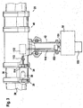
- Fig. 1 illustrated embodiment of the invention consists essentially of a tower 10 and a rotor 20 with two perpendicular to the rotor axis in opposite directions extending rotor blades 30.
- Fig. 1a the rotor is shown in a low-load parking position in which the rotor blades 30 are aligned horizontally.
- Fig. 1b is the in Fig. 1 illustrated wind turbine equipped with a control device 100, which can be input via an input 102, a rotational position of the rotor representing signal S. Further, the control device 100 can be input via inputs 108 setpoint values for the rotor rotation position.
- the deviation between the actual value of the rotational position of the rotor represented by the signal S and the target value for the rotor blade adjustment ⁇ 1 and ⁇ 2 and optionally adjustment speeds ⁇ ' 1 and ⁇ ' 2 calculated via the input 108 is calculated.
- These setpoint values for the blade adjustment are then set with a suitable blade adjustment device, where appropriate, the likewise calculated adjustment speed is used.
- the blade adjustment can be at the in Fig. 1 illustrated embodiment of the invention by rotating the rotor blades 30 to take place parallel to their longitudinal axes extending axes of rotation. As a result of this rotation of the rotor blades 30, a torque acting with respect to the rotor axis is generated, which leads to a reduction in the deviation between the actual value of the rotor rotational position and the desired value.
- the rotor blades can be equipped at their ends remote from the rotor axis with aerodynamic auxiliary devices 32, which are adjusted for adjusting the rotor or for bringing about the desired torque.
- a rotor blade 30 is connected via a designed as a large rolling bearing 34 rotary joint with a hub 40 of the rotor.
- the hub 40 is connected via a main shaft 42 to a transmission 50 of the wind turbine.
- the adjustment of the rotor blade 30 takes place at the in Fig. 2 illustrated embodiment of a torsion shaft 110, an angle gear 112 and a via the bevel gear 112 driven by the torsion shaft 110 Verstellritzel 114 which meshes with a toothing on the inner ring of the large rolling bearing 34.
- the torsion shaft 110 passes through the main shaft 42 designed as a hollow shaft and the gear 50.
- the torsion shaft 110 is a first brake system 120 acting between the rotor 20 and the torsion shaft 110 and a second between the torsion shaft 110 and the non-rotating Gondola of the wind turbine acting braking system 130 assigned. Further, the torsion shaft 110 is associated with a drive motor 140, which can cause a rotational movement of the torsion shaft 110 about its longitudinal axis. In this case, the drive motor 140 can optionally be supported on the rotor or on the fixed nacelle. An adjustment of the rotor blade 30 can be effected in this embodiment of the invention with the brake system 120 released by tightening the brake system 130 or by greater design of the brake system 130 in comparison to the brake system 120.
- a relative movement of the rotor to the torsion shaft 110 leads to a rotation of the Verstellritzels 114 which in turn leads to an adjustment of the rotor blade 30.
- the adjustment rate of the rotor blade can be adapted to the operating state. Additionally or alternatively, the adjustment of the rotor blade 30 can also be carried out with the aid of the drive motor 114.
- the torsion shaft 110 extends coaxially with the main shaft 42 of the wind turbine.
- a rotational movement of the rotor 20 via a switchable planetary gear 150, an intermediate shaft 151, an intermediate gear 152 and a torsion shaft 110 are transmitted to an angle gear 112 which drives a pinion 114.
- the pinion 114 meshes with an internal toothing of a pivot bearing 34.
- a tubular connecting piece is attached to the rotor hub 40.
- the tubular connecting piece 36 is connected to the rotor blade 30 via a further rotary bearing 39.
- an adjustment of the rotor blade 30 can be effected both by a rotation of the Verstellritzels 34 and by acting on the further pivot bearing 39 adjusting motor 38.
- the angle gear 112 is connected via a slip clutch 113 with the Verstellritzel 114.
- damage to the wind turbine with blocked rotor blade 30 can be prevented.
- the torsion shaft 110 is arranged eccentrically with respect to the rotor axis.
- a rotor shaft 42 and the gear 50 passing through push rod 200 is provided instead of the torsion shaft 110.
- This push rod 200 can be moved parallel to the rotor axis in a rotation of the rotor in the direction indicated by the double arrow A direction.
- the hub 40 facing away from the end of the push rod 200 is formed in the form of a threaded spindle, which is received in a corresponding spindle nut 210.
- the movement of the push rod 200 is transmitted to the rotor blade 30 via a cross member 212 received in the hub and a coupling rod 214 and can be converted, for example, into a rotation of this rotor blade 30.
- the spindle nut 210 is releasably secured to the transmission housing 50 so as to enable decoupling of the rotor blade displacement from rotor rotation.
- the invention is not limited to the embodiments explained with reference to the drawing.
- a wind turbine according to the invention may also have its own energy supply device, for example in the form of an auxiliary wind turbine.
- the invention can also be used not only in twin-bladed rotors but also in single-bladed rotors or rotors with more than two rotor blades.
Landscapes
- Engineering & Computer Science (AREA)
- Life Sciences & Earth Sciences (AREA)
- Sustainable Development (AREA)
- Sustainable Energy (AREA)
- Chemical & Material Sciences (AREA)
- Combustion & Propulsion (AREA)
- Mechanical Engineering (AREA)
- General Engineering & Computer Science (AREA)
- Wind Motors (AREA)
Claims (26)
- Eolienne avec un rotor (20) pouvant tourner autour d'un axe de rotation s'étendant à peu près horizontalement et présentant au moins une pale de rotor (30) s'étendant transversalement, à peu près perpendiculairement à l'axe de rotor, un dispositif de réglage pour le réglage de l'au moins une pale de rotor, dans laquelle, grâce au réglage, le couple généré par rapport à l'axe de rotor en cas de charge due au vent est variable, et avec un dispositif de stabilisation avec lequel le rotor (20) peut être stabilisé dans au moins une position de rotation à faible charge prescrite par rapport à l'axe de rotor,
caractérisée en ce que le dispositif de stabilisation présente un dispositif de couplage pouvant être accouplé au dispositif de réglage, avec lequel, en cas d'une déviation par rapport à la position de rotation prescrite ou en cas de mouvement de rotation du rotor (20) hors de la position de rotation prescrite, il est possible de procéder à un réglage de l'au moins une pale de rotor (30) pour la génération d'un couple contrecarrant cette déviation ou ce mouvement de rotation. - Eolienne selon la revendication 1, caractérisée en ce que l'au moins une pale de rotor (3) peut tourner avec le dispositif de réglage au moins en partie autour d'un axe de rotation s'étendant transversalement à l'axe de rotor et de préférence parallèlement à l'axe longitudinal de cette pale de rotor.
- Eolienne selon la revendication 1 ou 2, caractérisée en ce que l'on associe à l'au moins une pale de rotor (30) au moins un dispositif auxiliaire aérodynamique (32) tel que par exemple un volet de courbure, un volet déporteur, un spoiler et/ou un bout de pale rotatif pouvant être réglé avec le dispositif de réglage.
- Eolienne selon l'une des revendications précédentes, caractérisée en ce que le rotor (20) présente une ou deux pale (s) de rotor (30) est peut être stabilisé dans une position de rotation dans laquelle la pale de rotor (30) ou les pales de rotor (30) est (sont) orientée(s) à peu près horizontalement.
- Eolienne selon l'une des revendications précédentes, caractérisée en ce qu'un mouvement de rotation du rotor (20) peut être freiné par un réglage de l'au moins une pale de rotor (30) en utilisant le dispositif de couplage.
- Eolienne selon l'une des revendications précédentes, caractérisée en ce que le dispositif de régulation présente un capteur adapté pour la détection de la position de rotation du rotor ainsi qu'un dispositif de traitement de signaux (100) avec lequel on calcule, sur la base de signaux de capteur représentant la position de rotation du rotor (20), via un algorithme de régulation, une valeur de consigne (ϑ1, ϑ2) pour le réglage de pale, telle que par exemple un angle de réglage azimutal compte tenu de l'axe longitudinal, lequel est réglé par le dispositif de réglage.
- Eolienne selon l'une des revendications précédentes, caractérisée en ce que le dispositif de régulation présente un régulateur PI, un régulateur PID, un régulateur adaptif et/ou un régulateur Fuzzy.
- Eolienne selon l'une des revendications précédentes, caractérisée en ce qu'au moins un algorithme de régulation du dispositif de régulation et/ou une/des amplification(s) de celui-ci est variable en fonction de la direction du vent déterminée par exemple au moyen de signaux de girouette.
- Eolienne selon l'une des revendications précédentes, caractérisée par un dispositif d'alimentation en énergie dédié.
- Eolienne selon la revendication 9, caractérisée en ce que le dispositif d'alimentation en énergie présente au moins un accumulateur, un condensateur et/ou un groupe électrogène de secours, en particulier un générateur diesel.
- Eolienne selon la revendication 9 ou 10, caractérisée en ce que le dispositif d'alimentation en énergie présente une petite éolienne de secours de préférence montée sur une nacelle de l'éolienne.
- Eolienne selon la revendication 11, caractérisée en ce que l'éolienne de secours est un système dans la plage de performances comprise entre 5 et 100 kW, de préférence avec une vitesse nominale supérieure à 25 m/s.
- Eolienne selon la revendication 11 ou 12, caractérisée en ce que l'au moins une éolienne de secours est une machine à axe vertical dont le groupe moteur est disposé à l'intérieur d'une nacelle de l'éolienne.
- Eolienne selon l'une des revendications 11 à 13, caractérisée par un accumulateur tampon alimenté par l'éolienne de secours à partir duquel il est possible d'alimenter le dispositif de réglage, le dispositif de régulation et/ou le cas échéant des groupes auxiliaires de l'éolienne.
- Eolienne selon l'une des revendications précédentes, caractérisée en ce que le dispositif de couplage présente au moins un système de couplage avec lequel on suscite, via un couplage mécanique direct libérable lors d'un mouvement de rotation du rotor, un réglage de l'au moins une pale de rotor, de préférence de chacune de celles-ci.
- Eolienne selon la revendication 15, caractérisée en ce que le système de couplage présente un arbre de torsion (110) et/ou une tige de poussée (200) s'étendant de préférence au moins par tronçons approximativement parallèlement à l'axe de rotor, qui s'étend à l'intérieur d'un arbre principal (42) percé sur toute la longueur et/ou un logement de rotor et qui agit sur des moyens de réglage (112, 114, 212, 214) disposés de préférence à l'intérieur du moyeu de rotor (40) avec lesquels on suscite, lors d'un mouvement de rotation du rotor (20), un réglage de l'au moins une pale de rotor (30).
- Eolienne selon la revendication 16, caractérisée en ce que le réglage est suscité à l'apparition d'un mouvement relatif entre le rotor (20) et l'arbre de torsion (110).
- Eolienne selon la revendication 16 ou 17, caractérisée en ce que l'on associe à l'arbre de torsion (110) un premier système de freinage ou d'arrêt (120) agissant entre l'arbre de torsion (110) et le rotor (20), et un deuxième système de freinage ou d'arrêt (130) agissant entre l'arbre de torsion (110) et une nacelle non rotative de l'éolienne.
- Eolienne selon l'une des revendications 16 à 18, caractérisée en ce que l'on associe un dispositif d'entraînement (140) à l'arbre de torsion (110).
- Eolienne selon l'une des revendications 16 à 19, caractérisée en ce que l'arbre de torsion (110) s'étend au moins par tronçons à distance de l'axe de rotor.
- Eolienne selon l'une des revendications précédentes, caractérisée en ce que le dispositif de couplage présente un engrenage commutable, de préférence un engrenage planétaire (150) pour adapter le réglage suscité lors d'un mouvement de rotor de l'au moins une pale de rotor à l'état de fonctionnement de l'éolienne.
- Eolienne selon l'une des revendications précédentes, caractérisée par un système de régulation pour adapter le taux de réglage de l'au moins une pale de rotor lors du freinage à l'état de fonctionnement respectif.
- Eolienne selon l'une des revendications 16 à 22, caractérisée en ce que le système de régulation peut être exploité pour modifier le moment de freinage d'un dispositif de freinage accouplé à l'arbre de torsion.
- Eolienne selon l'une des revendications précédentes, caractérisée en ce que le dispositif de couplage présente au moins un accouplement à friction (113) via lequel on suscite le réglage de l'au moins une pale de rotor (30).
- Eolienne selon l'une des revendications précédentes, caractérisée en ce que le dispositif de réglage présente au moins deux systèmes de réglage (30, 39) indépendants l'un de l'autre, chacune d'entre eux pouvant être exploité également en cas de défaillance de l'autre système de réglage respectif pour le réglage de l'au moins une pale de rotor (30).
- Dispositif de stabilisation pour une éolienne selon l'une des revendications précédentes.
Applications Claiming Priority (2)
| Application Number | Priority Date | Filing Date | Title |
|---|---|---|---|
| DE10141098 | 2001-08-22 | ||
| DE10141098A DE10141098A1 (de) | 2001-08-22 | 2001-08-22 | Windkraftanlage |
Publications (3)
| Publication Number | Publication Date |
|---|---|
| EP1286049A2 EP1286049A2 (fr) | 2003-02-26 |
| EP1286049A3 EP1286049A3 (fr) | 2005-12-28 |
| EP1286049B1 true EP1286049B1 (fr) | 2017-03-29 |
Family
ID=7696219
Family Applications (1)
| Application Number | Title | Priority Date | Filing Date |
|---|---|---|---|
| EP02018223.4A Expired - Lifetime EP1286049B1 (fr) | 2001-08-22 | 2002-08-20 | Eolienne |
Country Status (3)
| Country | Link |
|---|---|
| US (1) | US6870281B2 (fr) |
| EP (1) | EP1286049B1 (fr) |
| DE (1) | DE10141098A1 (fr) |
Families Citing this family (38)
| Publication number | Priority date | Publication date | Assignee | Title |
|---|---|---|---|---|
| DE10317422A1 (de) * | 2003-04-15 | 2004-10-28 | Abb Patent Gmbh | Energieversorgungseinrichtung für ein Windkraftwerk |
| US7431567B1 (en) * | 2003-05-30 | 2008-10-07 | Northern Power Systems Inc. | Wind turbine having a direct-drive drivetrain |
| ES2280770T3 (es) * | 2003-09-03 | 2007-09-16 | General Electric Company | Sistema de control redundante de paso de pala para turbina de viento. |
| DE102004013624A1 (de) | 2004-03-19 | 2005-10-06 | Sb Contractor A/S | Verfahren zum Betreiben einer Windenergieanlage und Windenergieanlage |
| US7075192B2 (en) * | 2004-04-19 | 2006-07-11 | Northern Power Systems, Inc. | Direct drive wind turbine |
| DE102004024564B4 (de) * | 2004-05-18 | 2006-03-30 | Nordex Energy Gmbh | Verfahren zur Steuerung und Regelung einer Windenergieanlage sowie Windenergieanlage |
| DE102004024563B4 (de) | 2004-05-18 | 2008-01-10 | Nordex Energy Gmbh | Verfahren zur Erzeugung von Notstrom für eine Windenergieanlage mit einem Hilfsgenerator |
| AT504818A1 (de) | 2004-07-30 | 2008-08-15 | Windtec Consulting Gmbh | Triebstrang einer windkraftanlage |
| DE102004046260B4 (de) * | 2004-09-23 | 2007-05-16 | Nordex Energy Gmbh | Verfahren zum Betreiben einer Vorrichtung zum Verstellen eines Blatteinstellwinkels sowie eine Verstellvorrichtung |
| DE102004052598A1 (de) * | 2004-10-29 | 2006-05-04 | Aktiebolaget Skf | Windenergieanlage |
| ES2552691T3 (es) * | 2004-12-30 | 2015-12-01 | Vestas Wind Systems A/S | Turbina eólica que comprende un sistema de control de redundancia multiplicada y método para controlar una turbina eólica |
| DE102005038243B4 (de) * | 2005-08-12 | 2014-11-27 | S.B. Patent Holding Aps | Bremsanlage für eine Windkraftanlage |
| US7762771B2 (en) | 2005-10-13 | 2010-07-27 | General Electric Company | Device for driving a first part of a wind energy turbine with respect to a second part of the wind energy turbine |
| US7218012B1 (en) * | 2006-05-31 | 2007-05-15 | General Electric Company | Emergency pitch drive power supply |
| DE102006054666B4 (de) * | 2006-11-17 | 2010-01-14 | Repower Systems Ag | Schwingungsdämpfung einer Windenergieanlage |
| DE102007022511B4 (de) * | 2007-05-14 | 2009-07-30 | Repower Systems Ag | Windenergieanlage mit einer Verstelleinrichtung für die Rotorblätter |
| DE102007058746A1 (de) | 2007-06-18 | 2008-12-24 | Hanning & Kahl Gmbh & Co. Kg | Arretierungsvorrichtung für eine Windturbine |
| US7948100B2 (en) * | 2007-12-19 | 2011-05-24 | General Electric Company | Braking and positioning system for a wind turbine rotor |
| US20090167023A1 (en) * | 2007-12-27 | 2009-07-02 | Jacob Johannes Nies | Forward leaning tower top section |
| DE102008012957A1 (de) * | 2008-03-06 | 2009-09-10 | Repower Systems Ag | Verfahren zum Betreiben einer Windenergieanlage und Windenergieanlage |
| DE102008012956B4 (de) | 2008-03-06 | 2011-06-30 | REpower Systems AG, 22297 | Blattwinkelverstellratengrenzwertanpassung |
| DE202008008137U1 (de) * | 2008-06-19 | 2008-09-18 | Khd Humboldt Wedag Gmbh | Rollenpresse mit Getriebekupplung |
| DE102009004070A1 (de) | 2009-01-02 | 2010-07-08 | Aerodyn Engineering Gmbh | Windenergieanlage |
| EP2389510B1 (fr) * | 2009-01-22 | 2013-04-03 | Vestas Wind Systems A/S | Commande d'un rotor d'eolienne au cours d'un processus d'arret par tangage et dispositif de modification de surface |
| JP5284872B2 (ja) * | 2009-05-22 | 2013-09-11 | 株式会社日立製作所 | 水平軸風車 |
| EP2343455A1 (fr) * | 2010-01-07 | 2011-07-13 | Vestas Wind Systems A/S | Centrale éolienne dotée d'un actionneur de pas de pale de rotor |
| EP2524134B1 (fr) | 2010-01-14 | 2014-05-07 | Neptco, Inc. | Éléments pales de rotor d'éolienne et procédés de fabrication de ces éléments |
| US10137542B2 (en) | 2010-01-14 | 2018-11-27 | Senvion Gmbh | Wind turbine rotor blade components and machine for making same |
| DE102010005538A1 (de) * | 2010-01-23 | 2011-07-28 | Schaeffler Technologies GmbH & Co. KG, 91074 | Windenergieanlage mit einem oder mehreren Rotorblättern |
| JP4749504B1 (ja) * | 2010-10-14 | 2011-08-17 | 株式会社ビルメン鹿児島 | 風力発電装置の風車及び風力発電装置 |
| CA2757590A1 (fr) * | 2010-11-18 | 2012-05-18 | Envision Energy (Denmark) Aps | Equilibrage du systeme de pas |
| DE102010054631A1 (de) | 2010-12-15 | 2012-06-21 | Robert Bosch Gmbh | Antriebseinrichtung |
| DK177278B1 (en) | 2011-05-19 | 2012-09-17 | Envision Energy Denmark Aps | A wind turbine and associated control method |
| ITRM20110545A1 (it) * | 2011-10-14 | 2013-04-15 | Enel Green Power Spa | Generatore eolico con sistema di controllo attivo del passo di pala |
| US10502194B2 (en) | 2016-05-27 | 2019-12-10 | General Electric Company | Wind turbine bearings |
| CN106441829A (zh) * | 2016-08-30 | 2017-02-22 | 芜湖莫森泰克汽车科技股份有限公司 | 汽车天窗风载试验台 |
| EP3964706A1 (fr) * | 2020-09-02 | 2022-03-09 | General Electric Renovables España S.L. | Procédé de fonctionnement d'une éolienne, procédé de conception d'une éolienne et éolienne |
| EP4160008A1 (fr) * | 2021-10-04 | 2023-04-05 | General Electric Renovables España S.L. | Dispositifs et procédés de réduction de vibrations sur des éoliennes |
Family Cites Families (42)
| Publication number | Priority date | Publication date | Assignee | Title |
|---|---|---|---|---|
| US3770191A (en) * | 1971-06-28 | 1973-11-06 | Sorvall Inc Ivan | Means for stabilizing high speed rotors |
| EP0090799A1 (fr) * | 1981-10-13 | 1983-10-12 | Svensk Vindkraft Industri Ab (Sviab) | Dispositif de securite pour eoliennes |
| NL8201283A (nl) * | 1982-03-26 | 1983-10-17 | Fdo Techn Adviseurs | Deelbare gondel voor een windmolen. |
| US4449889A (en) * | 1983-01-20 | 1984-05-22 | Belden Ralph A | Windmill |
| US4789305A (en) * | 1985-04-26 | 1988-12-06 | Vaughen Jack F | Self-feathering rotary wing |
| US4726736A (en) * | 1985-09-17 | 1988-02-23 | Breuner Gerald L | Drag operated rotor pitch adjustment system for gyroplanes |
| DD252641A1 (de) * | 1986-09-11 | 1987-12-23 | Rostock Energiekombinat | Regeleinrichtung fuer windkraftanlagen |
| US5304036A (en) * | 1990-12-12 | 1994-04-19 | Sego Tool, Incorporated | Autogyro aircraft |
| DE69224525T2 (de) * | 1991-08-02 | 1998-08-27 | Boeing Co | Eingelassener heckrotor eines drehflügelflugzeuges um die drehmomentreaktion und gierlageregelung zu versorgen |
| US5213470A (en) * | 1991-08-16 | 1993-05-25 | Robert E. Lundquist | Wind turbine |
| US5155375A (en) * | 1991-09-19 | 1992-10-13 | U.S. Windpower, Inc. | Speed control system for a variable speed wind turbine |
| US5327647A (en) * | 1991-11-22 | 1994-07-12 | Energy Unlimited | Method for setting pitch on a windmill airfoil |
| US5527151A (en) * | 1992-03-04 | 1996-06-18 | Northern Power Systems, Inc. | Advanced wind turbine with lift-destroying aileron for shutdown |
| US5320491A (en) * | 1992-07-09 | 1994-06-14 | Northern Power Systems, Inc. | Wind turbine rotor aileron |
| US5263846A (en) * | 1992-09-17 | 1993-11-23 | The United States Of America As Represented By The Secretary Of The Army | Self-actuated rotor system |
| US5727926A (en) * | 1992-11-25 | 1998-03-17 | Kawasaki Jukogyo Kabushiki Kaisha | Pitch link for rotary wing aircraft and automatic adjuster thereof |
| FR2699595B1 (fr) * | 1992-12-23 | 1995-01-20 | Snecma | Dispositif de guidage en rotation d'un anneau de commande d'aubes pivotantes. |
| US5454153A (en) * | 1993-08-27 | 1995-10-03 | Noel; Hector | Adjustable assembly for use in the repair or replacement of a pitch change link or rod end of critical predetermined length |
| US5431540A (en) * | 1993-12-14 | 1995-07-11 | United Technologies Corporation | Main rotor pitch control rod subassembly |
| US5527152A (en) * | 1994-03-04 | 1996-06-18 | Northern Power Systems, Inc. | Advanced wind turbine with lift cancelling aileron for shutdown |
| EP0709571A3 (fr) * | 1994-10-25 | 1996-12-11 | Autoflug Energietech Gmbh | Position de repos à faible charge pour éolienne |
| US5584655A (en) * | 1994-12-21 | 1996-12-17 | The Wind Turbine Company | Rotor device and control for wind turbine |
| US5555144A (en) * | 1995-01-12 | 1996-09-10 | Seagate Technology, Inc. | Balancing system for a disc drive disc assembly |
| WO1997040943A1 (fr) * | 1996-04-30 | 1997-11-06 | Dade International Inc. | Appareil et procede de stabilisation d'un rotor de centrifugeuse |
| DE19618810A1 (de) * | 1996-05-10 | 1997-11-13 | Zf Luftfahrttechnik Gmbh | Hubschrauber |
| DE19627869A1 (de) * | 1996-07-11 | 1998-01-15 | Zf Luftfahrttechnik Gmbh | Hubschrauber |
| DE19717059C1 (de) * | 1997-04-23 | 1998-07-09 | Aerodyn Eng Gmbh | Verfahren zum Verbringen einer Windkraftanlage in eine Parkstellung |
| DE19731918B4 (de) * | 1997-07-25 | 2005-12-22 | Wobben, Aloys, Dipl.-Ing. | Windenergieanlage |
| EP1029176B1 (fr) * | 1997-11-04 | 2004-03-03 | WINDTEC Anlagenerrichtungs- und Consulting GmbH | Installation eolienne |
| FR2770826B1 (fr) * | 1997-11-07 | 2000-01-07 | Eurocopter France | Pale de rotor a volet orientable |
| EP1056640B1 (fr) * | 1998-02-20 | 2006-04-26 | Abraham E. Karem | Rotor a vitesse optimale |
| US6641365B2 (en) * | 1998-02-20 | 2003-11-04 | Abraham E. Karem | Optimum speed tilt rotor |
| US6065933A (en) * | 1998-06-16 | 2000-05-23 | Secord; Denver D. | Folding rotor blade/propeller drive and pitch control actuator |
| FR2784351B1 (fr) * | 1998-10-12 | 2000-12-08 | Eurocopter France | Dispositif et procede pour reduire les vibrations engendrees sur la structure d'un aeronef a voilure tournante, notamment un helicoptere |
| US6135713A (en) * | 1999-01-19 | 2000-10-24 | The Mcdonnell Douglas Helicopter Company | Helicopter rotor blade flap actuator government interest |
| IT1308395B1 (it) * | 1999-02-26 | 2001-12-17 | Finmeccanica Spa | Dispositivo di controllo dei passi ciclico e collettivo per un rotoredi un elicottero. |
| WO2000061942A1 (fr) * | 1999-04-14 | 2000-10-19 | Neg Micon A/S | Dispositif permettant d'ajuster le pas de pales d'éoliennes et methode permettant de faire cesser la rotation de l'arbre principal |
| DE10035333B4 (de) * | 2000-07-20 | 2008-08-14 | Eads Deutschland Gmbh | Rotorblatt mit Steuerklappen |
| US6608397B2 (en) * | 2000-11-09 | 2003-08-19 | Ntn Corporation | Wind driven electrical power generating apparatus |
| DE10061636B4 (de) * | 2000-12-11 | 2010-02-04 | Eurocopter Deutschland Gmbh | Rotorblatt mit Klappe und Klappenantrieb |
| DE10116479C2 (de) * | 2001-04-03 | 2003-12-11 | Eurocopter Deutschland | Verfahren und Regeleinrichtung zur Verstellung einer im Rotorblatt eines Hubschraubers schwenkbar gelagerten Klappe |
| US6726439B2 (en) * | 2001-08-22 | 2004-04-27 | Clipper Windpower Technology, Inc. | Retractable rotor blades for power generating wind and ocean current turbines and means for operating below set rotor torque limits |
-
2001
- 2001-08-22 DE DE10141098A patent/DE10141098A1/de not_active Withdrawn
-
2002
- 2002-08-20 EP EP02018223.4A patent/EP1286049B1/fr not_active Expired - Lifetime
- 2002-08-21 US US10/225,817 patent/US6870281B2/en not_active Expired - Lifetime
Non-Patent Citations (1)
| Title |
|---|
| None * |
Also Published As
| Publication number | Publication date |
|---|---|
| EP1286049A2 (fr) | 2003-02-26 |
| EP1286049A3 (fr) | 2005-12-28 |
| DE10141098A1 (de) | 2003-03-06 |
| US6870281B2 (en) | 2005-03-22 |
| US20030075929A1 (en) | 2003-04-24 |
Similar Documents
| Publication | Publication Date | Title |
|---|---|---|
| EP1286049B1 (fr) | Eolienne | |
| EP3365554B1 (fr) | Unité de déplacement et/ou d'entraînement, éolienne munie de ladite unité de déplacement et/ou d'entraînement, et procédé de commande de ladite unité de déplacement et/ou d'entraînement, | |
| EP2101058B1 (fr) | Méthode et dispositif pour tourner un composant d'une éolienne | |
| EP1290343B1 (fr) | Organe d'entrainement azimutal pour eoliennes | |
| EP3112676B1 (fr) | Procede de fonctionnement d'une eolienne et eolienne | |
| DE60311896T2 (de) | Redundantes steuerungssystem zur verstellung der anstellwinkel der rotorblätter einer windkraftanlage | |
| EP1794449B1 (fr) | Procede pour faire fonctionner un dispositif pour regler l'angle de reglage d'une plaque et procede de reglage associe | |
| DE60218328T2 (de) | Rotor mit teleskopischem blättern und steuerungskriterien | |
| EP1133638B1 (fr) | Organe d'entrainement azimutal pour eoliennes | |
| EP1882852A1 (fr) | Eolienne dotée d'un local technique | |
| DE102010031081A1 (de) | Windenergieanlage | |
| EP3265675A1 (fr) | Procédé pour faire fonctionner une éolienne | |
| EP2872776B1 (fr) | Éolienne pourvue d'un système de calage de pale | |
| EP2923079B1 (fr) | Procédé pour faire fonctionner une éolienne et éolienne | |
| EP3526469B1 (fr) | Unité de réglage et/ou d'entraînement, éolienne munie de ladite unité de réglage et/ou d'entraînement et procédé de commande de ladite unité de réglage et/ou d'entraînement | |
| EP2885533B1 (fr) | Installation génératrice d'énergie à flux | |
| EP2914844B1 (fr) | Procédé pour faire fonctionner une éolienne, éolienne et dispositif de commande pour une éolienne | |
| EP3339631A1 (fr) | Système d'éoliennes | |
| EP3702611B1 (fr) | Procédé de réglage d'un dispositif de réglage d'une éolienne | |
| EP2948678B1 (fr) | Procédé de réglage azimutal d'une éolienne, système de réglage azimutal et éolienne | |
| EP3489507A1 (fr) | Procédé et dispositif destinés au fonctionnement d'une éolienne | |
| EP3404256B1 (fr) | Dispositif d'ajustement des pales de rotor d'une installation génératrice d'énergie à flux | |
| EP3902993B1 (fr) | Procédé de maintien d'une partie mobile d'une éolienne | |
| DE102007042182A1 (de) | Windenergieanlage sowie Verfahren zum Betreiben einer Windenergieanlage |
Legal Events
| Date | Code | Title | Description |
|---|---|---|---|
| PUAI | Public reference made under article 153(3) epc to a published international application that has entered the european phase |
Free format text: ORIGINAL CODE: 0009012 |
|
| AK | Designated contracting states |
Kind code of ref document: A2 Designated state(s): AT BE BG CH CY CZ DE DK EE ES FI FR GB GR IE IT LI LU MC NL PT SE SK TR Designated state(s): AT BE BG CH CY CZ DE DK EE ES FI FR GB GR IE IT LI LU MC NL PT SE SK TR |
|
| AX | Request for extension of the european patent |
Extension state: AL LT LV MK RO SI |
|
| RAP1 | Party data changed (applicant data changed or rights of an application transferred) |
Owner name: GENERAL ELECTRIC COMPANY |
|
| PUAL | Search report despatched |
Free format text: ORIGINAL CODE: 0009013 |
|
| AK | Designated contracting states |
Kind code of ref document: A3 Designated state(s): AT BE BG CH CY CZ DE DK EE ES FI FR GB GR IE IT LI LU MC NL PT SE SK TR |
|
| AX | Request for extension of the european patent |
Extension state: AL LT LV MK RO SI |
|
| 17P | Request for examination filed |
Effective date: 20060628 |
|
| AKX | Designation fees paid |
Designated state(s): DE GB IE NL |
|
| 17Q | First examination report despatched |
Effective date: 20100215 |
|
| 17Q | First examination report despatched |
Effective date: 20100917 |
|
| GRAP | Despatch of communication of intention to grant a patent |
Free format text: ORIGINAL CODE: EPIDOSNIGR1 |
|
| INTG | Intention to grant announced |
Effective date: 20160405 |
|
| GRAJ | Information related to disapproval of communication of intention to grant by the applicant or resumption of examination proceedings by the epo deleted |
Free format text: ORIGINAL CODE: EPIDOSDIGR1 |
|
| INTC | Intention to grant announced (deleted) | ||
| GRAP | Despatch of communication of intention to grant a patent |
Free format text: ORIGINAL CODE: EPIDOSNIGR1 |
|
| INTG | Intention to grant announced |
Effective date: 20161010 |
|
| GRAS | Grant fee paid |
Free format text: ORIGINAL CODE: EPIDOSNIGR3 |
|
| GRAA | (expected) grant |
Free format text: ORIGINAL CODE: 0009210 |
|
| AK | Designated contracting states |
Kind code of ref document: B1 Designated state(s): DE GB IE NL |
|
| REG | Reference to a national code |
Ref country code: GB Ref legal event code: FG4D Free format text: NOT ENGLISH |
|
| REG | Reference to a national code |
Ref country code: IE Ref legal event code: FG4D Free format text: LANGUAGE OF EP DOCUMENT: GERMAN |
|
| REG | Reference to a national code |
Ref country code: DE Ref legal event code: R096 Ref document number: 50216224 Country of ref document: DE |
|
| REG | Reference to a national code |
Ref country code: NL Ref legal event code: MP Effective date: 20170329 |
|
| PG25 | Lapsed in a contracting state [announced via postgrant information from national office to epo] |
Ref country code: NL Free format text: LAPSE BECAUSE OF FAILURE TO SUBMIT A TRANSLATION OF THE DESCRIPTION OR TO PAY THE FEE WITHIN THE PRESCRIBED TIME-LIMIT Effective date: 20170329 |
|
| REG | Reference to a national code |
Ref country code: DE Ref legal event code: R097 Ref document number: 50216224 Country of ref document: DE |
|
| PLBE | No opposition filed within time limit |
Free format text: ORIGINAL CODE: 0009261 |
|
| STAA | Information on the status of an ep patent application or granted ep patent |
Free format text: STATUS: NO OPPOSITION FILED WITHIN TIME LIMIT |
|
| 26N | No opposition filed |
Effective date: 20180103 |
|
| GBPC | Gb: european patent ceased through non-payment of renewal fee |
Effective date: 20170820 |
|
| REG | Reference to a national code |
Ref country code: IE Ref legal event code: MM4A |
|
| PG25 | Lapsed in a contracting state [announced via postgrant information from national office to epo] |
Ref country code: IE Free format text: LAPSE BECAUSE OF NON-PAYMENT OF DUE FEES Effective date: 20170820 Ref country code: GB Free format text: LAPSE BECAUSE OF NON-PAYMENT OF DUE FEES Effective date: 20170820 |
|
| PGFP | Annual fee paid to national office [announced via postgrant information from national office to epo] |
Ref country code: DE Payment date: 20200721 Year of fee payment: 19 |
|
| REG | Reference to a national code |
Ref country code: DE Ref legal event code: R119 Ref document number: 50216224 Country of ref document: DE |
|
| PG25 | Lapsed in a contracting state [announced via postgrant information from national office to epo] |
Ref country code: DE Free format text: LAPSE BECAUSE OF NON-PAYMENT OF DUE FEES Effective date: 20220301 |