EP1285268B1 - Detection system for sorting apparatus - Google Patents
Detection system for sorting apparatus Download PDFInfo
- Publication number
- EP1285268B1 EP1285268B1 EP01934635A EP01934635A EP1285268B1 EP 1285268 B1 EP1285268 B1 EP 1285268B1 EP 01934635 A EP01934635 A EP 01934635A EP 01934635 A EP01934635 A EP 01934635A EP 1285268 B1 EP1285268 B1 EP 1285268B1
- Authority
- EP
- European Patent Office
- Prior art keywords
- product
- tapping
- receiver section
- section
- detection device
- Prior art date
- Legal status (The legal status is an assumption and is not a legal conclusion. Google has not performed a legal analysis and makes no representation as to the accuracy of the status listed.)
- Expired - Lifetime
Links
Images


Classifications
-
- G—PHYSICS
- G01—MEASURING; TESTING
- G01N—INVESTIGATING OR ANALYSING MATERIALS BY DETERMINING THEIR CHEMICAL OR PHYSICAL PROPERTIES
- G01N3/00—Investigating strength properties of solid materials by application of mechanical stress
- G01N3/40—Investigating hardness or rebound hardness
- G01N3/405—Investigating hardness or rebound hardness by determining the vibration frequency of a sensing element in contact with the specimen
-
- G—PHYSICS
- G01—MEASURING; TESTING
- G01N—INVESTIGATING OR ANALYSING MATERIALS BY DETERMINING THEIR CHEMICAL OR PHYSICAL PROPERTIES
- G01N33/00—Investigating or analysing materials by specific methods not covered by groups G01N1/00 - G01N31/00
- G01N33/02—Food
- G01N33/025—Fruits or vegetables
-
- G—PHYSICS
- G01—MEASURING; TESTING
- G01N—INVESTIGATING OR ANALYSING MATERIALS BY DETERMINING THEIR CHEMICAL OR PHYSICAL PROPERTIES
- G01N2291/00—Indexing codes associated with group G01N29/00
- G01N2291/02—Indexing codes associated with the analysed material
- G01N2291/028—Material parameters
- G01N2291/02827—Elastic parameters, strength or force
Definitions
- the present invention relates to a system for determining characteristics of products which are conveyed on a conveying apparatus and pass the system.
- the invention relates to a system for determining characteristics of products of generally unequal size, e.g. apples, which are conveyed on product carriers, such as rollers of a conveying apparatus, and pass the system, the system comprising a conveying apparatus for continuously conveying product carriers, a detection device, arranged at some distance from the products, with a transmitter section and a receiver section, as well as a signal processing unit for processing signals to and from the system, including the signals of the receiver section for determining the characteristics.
- product carriers such as rollers of a conveying apparatus
- W098/52037 discloses a device with a transmitter and receiver, in particular for tapping fruit and then recording the tap signal, which device comes down under spring action from one product onto the next product passing under it, this device rolling over such a product as it passes. During this rolling movement, tapping and recording take place.
- Such a device has the disadvantage that, in particular in making a transition from the clearly smaller to the considerably larger products and following same, a relatively great difference in height is to be bridged. The consequent coming down onto a next product from some height may cause damage, certainly in the case of delicate products, such as, for instance, pears. Moreover, the operation of this device will be substantially limited to a vertical plane.
- system according to the invention is characterized in that the system further comprises:
- the transmitter section comprises a tapping device and the receiver section comprises a microphone, which are both accommodated in the same housing.
- the tapping device comprises a tapping rod which is movable in a guide tube, the tapping device being energized such that during the passage of the product the tapping rod is moved to the product and, after tapping the product, is retracted.
- the present invention is characterized in that the receiver section comprises a microphone accommodated in a housing, and that the transmitter section, being spring-mounted with a clamping device between the product carriers and moving along with the conveying apparatus, comprises a tapping rod which, when passing the receiver section, is brought out of its equilibrium position, taps the product and moves back.
- this alternative exemplary embodiment is the flexibility in positioning the receiver, so that in this way, for different types of fruits, such as, for instance, apples, pears, kiwis, and melons, an optimum measuring signal can be obtained.
- JP 03 039649 discloses a device for measuring the internal quality of fruits by tapping on the fruit and by detecting an oscillating wave of vegetable or fruit with a sensor.
- the known device analyses the waveform and compares the waveform with standard values to decide the grade of the fruit or vegetable.
- the shock or tapping means 4 and the sensor means 32 are positioned relative to the fruit or vegetable based on a measurement of the size of the fruit which measurement is performed before the measurement of the internal quality.
- the shock means 4 and at least one of the sensor parts 32 extend in the transport path of the fruit when the measurement takes place in a measurement position.
- the shock means 4 and the said sensor part 32 extending in the transport path of the fruit are removed from this path by lifting the sensor parts 32 and the shock means 4 with the lifting piston 331 when a next fruit or vegetable has to be positioned in the measurement position.
- the sensor part 32 extending in the transport path is in contact with the fruit or vegetable when the measurement takes place, it is inevitable that the fruit or vegetable is stationary when the measurement of the internal quality is performed. After said quality measurement, the sensor parts 32 and the shock means 4 are lifted again and the next fruit is positioned in the measurement position.
- the system according to the invention is characterized in that the direction of movement of the tapping rod is vertical.
- This embodiment makes it possible to accurately tailor the movement of the tapping rod to its weight, and hence to control the impact on the fruit.
- Fig. 1 shows a detection system 1 above a roller conveyor 2, with products P disposed on rollers 21, usually hourglass-shaped.
- rollers 21 are customarily mounted on shafts arranged between, for instance, two endless chains and advanced in the direction of arrow A by means of a gear driven by a motor (not shown in the drawing for clarity).
- the rollers 21 themselves may be rotated, for instance as indicated by the arrow, so that, as a result, the products will rotate as well. This may be necessary, for instance, when several points on the product are to be probed, for instance by tapping or also for obtaining optical data.
- a distance sensor 3 for instance a photoelectric cell or camera
- the size, or also the height, of the product P is determined, and the associated scanning signal is transmitted along signal path 31, for instance a cord or optical fiber, to a signal processing device 30, for instance a computer.
- a control signal is supplied via signal path 32 to a detection device 5, for it to be positioned at the proper height when the product P passes.
- This detection device comprises a transmitter section and a receiver section, which will be described hereinafter in more detail.
- Fig. 1 schematically shows an exemplary embodiment of a detection device 5, with transmitter and receiver accommodated as a single unit 4 in a housing or holder 8.
- the transmitter is formed by a tapping device, in particular a tapping rod 6, which, as indicated, is vertically movable in a guide tube 6a.
- the drive can be effected in a variety of ways, such as, for instance, electromagnetically or magnetically, or through a combination thereof, or also with a mechanical spring system.
- the receiver comprises a microphone 7 which, after the product has been tapped, records the sound produced.
- Signals for driving the transmitter and for processing the signals of the receiver are processed in a conventional manner in computer 30, for which purpose the signals are guided again along the same, or a similar, signal path 32.
- the hardness, also called firmness, of a product such as an apple, tomato, or kiwi
- the hardness, also called firmness, of a product can be determined on-line during sorting on a sorting machine, and in this manner, often real-time, serve also as a selection criterion.
- the vertical displacement in the direction h indicated is provided by bar 9 which is connected with the housing 8 through a connecting element 11.
- This connecting element 11 can be, for instance, a spring-biased pivot.
- driving unit 10 for instance a stepping motor, in particular a linear stepping motor, for instance with servo control
- the bar 9 can, in accordance with the scanning signal of sensor 3, be steered in the right direction and to the correct height.
- the detection device can moreover be so designed that a part of housing 8 is formed from resilient material, so that during tapping the housing is pressed slightly onto and against the product. It will be clear to anyone skilled in the art that other types of transmitters and receivers, such as laser means or piezo elements, can be used.
- Figs. 2 and 3 show a second exemplary embodiment according to the invention, in which the transmitter and receiver are not accommodated in the same housing.
- the transmitter represented in more detail in Fig. 3, is an array of tapping rods 16, vertically displaceable between the rollers in a plane parallel to the roller shafts 23, being connected through a generally resilient bending portion 17a with a central holding element 17, this holding element in turn being mounted with two clamping halves 19a and 19b of clamp 19, which is clamped between the shafts 23 of the roller conveyor 2.
- These clamping halves can, for instance through a sliding connection, move relative to each other, to thereby take up the increase in distance between the shafts upon a change in the direction of movement when the endless conveyor passes through a bend.
- Activation of the transmitter takes place by leading the cam blocks 22 mounted on the rods 16, prior to tapping, over a cog (not shown) positioned under the rollers, and subsequently allowing them to spring back, the deflection being such that the product will be tapped from below.
- the receiver, a microphone 7, in this embodiment is accommodated in a housing 18, which in turn is mounted on a bar 9, which in turn is driven by a drive 10. It will be clear to anyone skilled in the art that the tapping movement of these rods 16 can also be effected in a different manner, for instance electromagnetically. In this exemplary embodiment, it is also possible to use the above-mentioned receivers, viz. laser means or piezo elements.
- the rotation referred to could be of importance.
- absorption and/or reflection of well-defined wavelengths of light irradiated onto fruits is/are to be determined, for instance to determine sugar content, moisture content, water concentration, or acidity, a combination of measurements in several directions may be required.
- the embodiments according to Fig. 1 or 2 can be modified such that, instead of the housings 8 and 18, a small wheel, itself mounted, for instance, on the end of an arm which functions as lever, with transmitter and receiver, or receiver alone, mounted on the shaft, is rolled over the products and, as taught by the present invention, when rolling over the products is, in a controlled manner, timely moved with the arm to a next product and from a previous product to prevent undesired impacts.
- Fig. 4 shows a third exemplary embodiment according to the invention.
- the tapping rod 6 having therein a magnet 6b of corresponding, often small, dimensions, is operatively driven downwards and retracted again with an electromagnet.
- This electromagnet consists of a coil housing 60 and a coil 61. Again, the tapping rod 6 is movable in a guide tube 6a, which is formed in the coil housing 60. Also accommodated in the coil housing is the microphone 7. After performing the tapping movement, the tapping rod is retracted and then butts at the end of the guide tube against a buffer block 62.
- This detection system is done with a linear motor 70, having therein a movement shaft 71 which is mounted with a mounting screw 72 on a mounting plate 66 connected with the coil housing 60.
- a bush 63 is provided.
- This bush can be substantially circular-symmetrical, but may also consist of two elongate, mutually symmetrical halves.
- a spring coupling with the coil housing has been obtained by means of buffer rubbers 64 and spring elements 65, of great advantage both in the proper positioning of the detection device and in taking up unexpected and large shocks.
- these spring elements consist of a stem 65b, resiliently connected with a buffer rubber 64 and attached at its upper end, through a hole in the mounting plate 66, to a cover plate 65c.
- a compression spring 65a around the stem 65b presses the cover plate 65c against the plate 66.
- the hole-stem connection allows a flexible positioning of the detection device in a highly suitable manner.
- spring elements 65 there are provided four spring elements 65, viz. one at each corner, but other geometries can be used as well.
- a draw spring 80 is tensioned, to pull the motor from the product immediately in the event of an energization drop-out, to thereby prevent damage to any further passing products. It will be clear to anyone skilled in the art that the strength of this spring is chosen such that in normal use the motor will not in any way be hindered by it.
- a curve with follower can be arranged, so as to have the detection device follow a well-defined curve during measurement.
- Fig. 5 schematically represents three coil units mounted side by side on the sorting machine.
- Coils 610 of linear motors with cores 710 are attached to the sorting machine with mounting blocks 800.
- the two outermost motors are connected with the detection device 5 which can be placed on a passing product.
- Damping elements 650 provide for a suitable placement on the product.
- the central core with tapper can be driven.
- Figs. 6 and 7 concern a detection device 510 for light, having in particular a light receiving device 900, for instance a fiber.
- a screening cap portion 520 of this detection device can be placed on a passing product with two units with mounting blocks 800, coils 610, and cores of a linear motor, or with a linear motor 1000, both mounted on the sorting machine again. In this way, the collection or reception of both incident scattered light and reflective incident light can be effectively avoided.
- linear motors An advantage of the use of linear motors is the possibility of suitably choosing parameters such as speed and mass. These embodiments have been found to allow sorting at passing speeds of up to 10 to 20 products per second.
Landscapes
- Chemical & Material Sciences (AREA)
- Health & Medical Sciences (AREA)
- Life Sciences & Earth Sciences (AREA)
- Immunology (AREA)
- Analytical Chemistry (AREA)
- Biochemistry (AREA)
- General Health & Medical Sciences (AREA)
- General Physics & Mathematics (AREA)
- Physics & Mathematics (AREA)
- Pathology (AREA)
- Engineering & Computer Science (AREA)
- Food Science & Technology (AREA)
- Medicinal Chemistry (AREA)
- Sorting Of Articles (AREA)
- Investigating Or Analysing Materials By Optical Means (AREA)
- Investigating Or Analyzing Materials By The Use Of Ultrasonic Waves (AREA)
- Investigating Materials By The Use Of Optical Means Adapted For Particular Applications (AREA)
Abstract
Description
- The present invention relates to a system for determining characteristics of products which are conveyed on a conveying apparatus and pass the system.
- More particularly, the invention relates to a system for determining characteristics of products of generally unequal size, e.g. apples, which are conveyed on product carriers, such as rollers of a conveying apparatus, and pass the system, the system comprising a conveying apparatus for continuously conveying product carriers, a detection device, arranged at some distance from the products, with a transmitter section and a receiver section, as well as a signal processing unit for processing signals to and from the system, including the signals of the receiver section for determining the characteristics.
- Such systems are generally known in the art of selecting and sorting products, such as fruit, vegetables, and eggs. W098/52037, for instance, discloses a device with a transmitter and receiver, in particular for tapping fruit and then recording the tap signal, which device comes down under spring action from one product onto the next product passing under it, this device rolling over such a product as it passes. During this rolling movement, tapping and recording take place.
- Such a device has the disadvantage that, in particular in making a transition from the clearly smaller to the considerably larger products and following same, a relatively great difference in height is to be bridged. The consequent coming down onto a next product from some height may cause damage, certainly in the case of delicate products, such as, for instance, pears. Moreover, the operation of this device will be substantially limited to a vertical plane.
- To remedy the drawbacks mentioned, the system according to the invention is characterized in that the system further comprises:
- a sensor arranged for, prior to the passage of a product, scanning the size of each passing product and producing a corresponding scanning signal, and
- a displacement device, arranged for positioning, in accordance with each scanning signal, at least the receiver section of the detection device at a well-defined distance during the passage of each product.
- In an advantageous manner measurements are thus obtained which are comparable for the successive products. Moreover, damage to products which are being conveyed with the conveying apparatus, such as, for instance, a conveying apparatus with rollers or diabolos mounted on shafts which are advanced by endless chains, can be prevented.
- In a particular embodiment of the present invention, the transmitter section comprises a tapping device and the receiver section comprises a microphone, which are both accommodated in the same housing.
- According to a further embodiment, the tapping device comprises a tapping rod which is movable in a guide tube, the tapping device being energized such that during the passage of the product the tapping rod is moved to the product and, after tapping the product, is retracted.
- In another exemplary embodiment, the present invention is characterized in that the receiver section comprises a microphone accommodated in a housing, and that the transmitter section, being spring-mounted with a clamping device between the product carriers and moving along with the conveying apparatus, comprises a tapping rod which, when passing the receiver section, is brought out of its equilibrium position, taps the product and moves back.
- To be seen as a great advantage of this alternative exemplary embodiment is the flexibility in positioning the receiver, so that in this way, for different types of fruits, such as, for instance, apples, pears, kiwis, and melons, an optimum measuring signal can be obtained.
- It should be noted that JP 03 039649 discloses a device for measuring the internal quality of fruits by tapping on the fruit and by detecting an oscillating wave of vegetable or fruit with a sensor. The known device analyses the waveform and compares the waveform with standard values to decide the grade of the fruit or vegetable. The shock or tapping means 4 and the sensor means 32 are positioned relative to the fruit or vegetable based on a measurement of the size of the fruit which measurement is performed before the measurement of the internal quality. As is clear from figures 1, 8 and 10 of the Japanese publication, the shock means 4 and at least one of the
sensor parts 32 extend in the transport path of the fruit when the measurement takes place in a measurement position. Consequently, it is necessary that the shock means 4 and the saidsensor part 32 extending in the transport path of the fruit are removed from this path by lifting thesensor parts 32 and the shock means 4 with the lifting piston 331 when a next fruit or vegetable has to be positioned in the measurement position. In view of the fact that thesensor part 32 extending in the transport path is in contact with the fruit or vegetable when the measurement takes place, it is inevitable that the fruit or vegetable is stationary when the measurement of the internal quality is performed. After said quality measurement, thesensor parts 32 and the shock means 4 are lifted again and the next fruit is positioned in the measurement position. There is no disclosure in this document for a continuously moving conveyor on which the measurement of the internal quality is performed. - Further, the system according to the invention is characterized in that the direction of movement of the tapping rod is vertical.
- This embodiment makes it possible to accurately tailor the movement of the tapping rod to its weight, and hence to control the impact on the fruit.
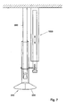
- The present invention will be further elucidated hereinafter with reference to the accompanying drawings, in which:
- Fig. 1 schematically shows an elevation of a first embodiment of the present invention;
- Fig. 2 schematically shows an elevation of a second embodiment of the present invention;
- Fig. 3 schematically shows a further detail of the second embodiment in top plan view;
- Fig. 4 schematically shows a third exemplary embodiment of the invention; and
- Figs. 5, 6 and 7 show slightly modified exemplary embodiments.
-
- Fig. 1 shows a detection system 1 above a
roller conveyor 2, with products P disposed onrollers 21, usually hourglass-shaped. Theserollers 21 are customarily mounted on shafts arranged between, for instance, two endless chains and advanced in the direction of arrow A by means of a gear driven by a motor (not shown in the drawing for clarity). If necessary, therollers 21 themselves may be rotated, for instance as indicated by the arrow, so that, as a result, the products will rotate as well. This may be necessary, for instance, when several points on the product are to be probed, for instance by tapping or also for obtaining optical data. - With a
distance sensor 3, for instance a photoelectric cell or camera, the size, or also the height, of the product P is determined, and the associated scanning signal is transmitted alongsignal path 31, for instance a cord or optical fiber, to asignal processing device 30, for instance a computer. Thereafter, in accordance with this scanning signal, a control signal is supplied viasignal path 32 to adetection device 5, for it to be positioned at the proper height when the product P passes. This detection device comprises a transmitter section and a receiver section, which will be described hereinafter in more detail. - Fig. 1 schematically shows an exemplary embodiment of a
detection device 5, with transmitter and receiver accommodated as asingle unit 4 in a housing orholder 8. The transmitter is formed by a tapping device, in particular atapping rod 6, which, as indicated, is vertically movable in aguide tube 6a. The drive can be effected in a variety of ways, such as, for instance, electromagnetically or magnetically, or through a combination thereof, or also with a mechanical spring system. The receiver comprises amicrophone 7 which, after the product has been tapped, records the sound produced. Signals for driving the transmitter and for processing the signals of the receiver are processed in a conventional manner incomputer 30, for which purpose the signals are guided again along the same, or a similar,signal path 32. With such a tapping device, the hardness, also called firmness, of a product, such as an apple, tomato, or kiwi, can be determined on-line during sorting on a sorting machine, and in this manner, often real-time, serve also as a selection criterion. - The vertical displacement in the direction h indicated is provided by
bar 9 which is connected with thehousing 8 through a connectingelement 11. This connectingelement 11 can be, for instance, a spring-biased pivot. Withdriving unit 10, for instance a stepping motor, in particular a linear stepping motor, for instance with servo control, thebar 9 can, in accordance with the scanning signal ofsensor 3, be steered in the right direction and to the correct height. The detection device can moreover be so designed that a part ofhousing 8 is formed from resilient material, so that during tapping the housing is pressed slightly onto and against the product. It will be clear to anyone skilled in the art that other types of transmitters and receivers, such as laser means or piezo elements, can be used. - Figs. 2 and 3 show a second exemplary embodiment according to the invention, in which the transmitter and receiver are not accommodated in the same housing. The transmitter, represented in more detail in Fig. 3, is an array of
tapping rods 16, vertically displaceable between the rollers in a plane parallel to theroller shafts 23, being connected through a generallyresilient bending portion 17a with acentral holding element 17, this holding element in turn being mounted with twoclamping halves clamp 19, which is clamped between theshafts 23 of theroller conveyor 2. These clamping halves can, for instance through a sliding connection, move relative to each other, to thereby take up the increase in distance between the shafts upon a change in the direction of movement when the endless conveyor passes through a bend. Activation of the transmitter takes place by leading thecam blocks 22 mounted on therods 16, prior to tapping, over a cog (not shown) positioned under the rollers, and subsequently allowing them to spring back, the deflection being such that the product will be tapped from below. The receiver, amicrophone 7, in this embodiment is accommodated in ahousing 18, which in turn is mounted on abar 9, which in turn is driven by adrive 10. It will be clear to anyone skilled in the art that the tapping movement of theserods 16 can also be effected in a different manner, for instance electromagnetically. In this exemplary embodiment, it is also possible to use the above-mentioned receivers, viz. laser means or piezo elements. - The above embodiments show that with small modifications, measurements can also be performed in other planes than the above-mentioned vertical plane. This can be of great advantage both in tapping measurements aimed at receiving resonance signals, and in optical measurements to determine absorption and/or reflection coefficients, both often direction-dependent. Moreover, a further modification will enable a rotation of the detection device in the vertical plane, yielding a positioning not only in terms of distance but also at an angle.
- In particular for the above-mentioned optical measurements, the rotation referred to could be of importance. When with the detection device absorption and/or reflection of well-defined wavelengths of light irradiated onto fruits is/are to be determined, for instance to determine sugar content, moisture content, water concentration, or acidity, a combination of measurements in several directions may be required.
- In view of the above, it will be clear to anyone skilled in the art that placing several detection systems along a sorting line can be of great advantage. In this way, sets of measurements for the same fruit can be obtained. Thus, repeat measurements can be performed and selection criteria can be defined more closely, whilst data processing can be carried out automatically in a conventional manner.
- In a further embodiment, the embodiments according to Fig. 1 or 2 can be modified such that, instead of the
housings - Fig. 4 shows a third exemplary embodiment according to the invention. The tapping
rod 6 having therein amagnet 6b of corresponding, often small, dimensions, is operatively driven downwards and retracted again with an electromagnet. This electromagnet consists of a coil housing 60 and acoil 61. Again, the tappingrod 6 is movable in aguide tube 6a, which is formed in the coil housing 60. Also accommodated in the coil housing is themicrophone 7. After performing the tapping movement, the tapping rod is retracted and then butts at the end of the guide tube against abuffer block 62. - The positioning of this detection system at the proper height above a product P is done with a
linear motor 70, having therein amovement shaft 71 which is mounted with a mountingscrew 72 on a mountingplate 66 connected with the coil housing 60. - To place the unit with tapping rod on a product P in proper contact, a bush 63 is provided. This bush can be substantially circular-symmetrical, but may also consist of two elongate, mutually symmetrical halves. Furthermore, a spring coupling with the coil housing has been obtained by means of
buffer rubbers 64 andspring elements 65, of great advantage both in the proper positioning of the detection device and in taking up unexpected and large shocks. In particular, these spring elements consist of astem 65b, resiliently connected with abuffer rubber 64 and attached at its upper end, through a hole in the mountingplate 66, to acover plate 65c. Acompression spring 65a around thestem 65b presses thecover plate 65c against theplate 66. It will be clear to anyone skilled in the art that the hole-stem connection allows a flexible positioning of the detection device in a highly suitable manner. Conventionally, there are provided fourspring elements 65, viz. one at each corner, but other geometries can be used as well. - In order to prevent undesired rotation between the mounting plate and the upper end of the linear motor, there extends along the motor a guide tube or
bar 73, along which the motor can move in the intended direction. - Also extending in the direction of displacement of the motor, a
draw spring 80 is tensioned, to pull the motor from the product immediately in the event of an energization drop-out, to thereby prevent damage to any further passing products. It will be clear to anyone skilled in the art that the strength of this spring is chosen such that in normal use the motor will not in any way be hindered by it. - In an embodiment not shown, as a connecting element, a curve with follower can be arranged, so as to have the detection device follow a well-defined curve during measurement.
- In Figs. 5, 6 and 7, slightly modified exemplary embodiments are shown.
- Fig. 5 schematically represents three coil units mounted side by side on the sorting machine.
Coils 610 of linear motors withcores 710 are attached to the sorting machine with mountingblocks 800. The two outermost motors are connected with thedetection device 5 which can be placed on a passing product. Dampingelements 650 provide for a suitable placement on the product. Likewise with a linear motor, the central core with tapper can be driven. - Figs. 6 and 7 concern a
detection device 510 for light, having in particular alight receiving device 900, for instance a fiber. Ascreening cap portion 520 of this detection device can be placed on a passing product with two units with mountingblocks 800, coils 610, and cores of a linear motor, or with alinear motor 1000, both mounted on the sorting machine again. In this way, the collection or reception of both incident scattered light and reflective incident light can be effectively avoided. - An advantage of the use of linear motors is the possibility of suitably choosing parameters such as speed and mass. These embodiments have been found to allow sorting at passing speeds of up to 10 to 20 products per second.
- It will be clear to anyone skilled in the art that small modifications can be made in the exemplary embodiments herein, which are understood to fall within the scope of the appended claims.
Claims (14)
- A system for determining characteristics of products of generally unequal size, e.g. apples, which are conveyed on product carriers, such as rollers of a conveying apparatus, and pass the system, the system comprising a conveying apparatus for continuously conveying product carriers, a detection device, arranged at some distance from the products, having a transmitter section and a receiver section, as well as a signal processing unit for processing signals to and from the system, including the signals of the receiver section for determining the characteristics, characterized in that the system further comprises:a sensor arranged for, prior to the passage of a product, scanning the size of each passing product and producing a corresponding scanning signal, anda displacement device, for positioning, in accordance with each scanning signal, at least the receiver section of the detection device at a well-defined distance during the passage of each product.
- A system according to claim 1, characterized in that the transmitter section comprises a tapping device and the receiver section comprises a microphone which are both accommodated in the same housing.
- A system according to claim 2, characterized in that the tapping device comprises a tapping rod which is movable in a guide tube, the tapping device being energized such that during the passage of the product the tapping rod is moved to the product and after tapping the product is retracted.
- A system according to claim 1, characterized in that the receiver section comprises a microphone accommodated in a housing, and that the transmitter section, spring- mounted between the product carriers with a clamping device and moving along with the conveying apparatus, comprises a tapping rod which, when passing the receiver section, is brought out of its equilibrium position, taps the product and moves back.
- A system according to any one of the preceding claims, characterized in that the direction of movement of the tapping rod is vertical.
- A system according to claim 3, characterized in that the guide tube is a part of an electromagnet with coil housing and coil, the coil housing being connected with the displacement device through spring elements.
- A system according to claim 6, characterized in that the coil housing is connected with the displacement device through four spring elements.
- A system according to claim 1, characterized in that both the receiver section and the transmitter section are positioned at a well-defined distance.
- A system according to claim 8, characterized in that each section is positioned with a linear motor.
- A system according to claim 1, characterized in that the detection device comprises a light receiving device.
- A system according to claim 10, characterized in that, of the light receiving device, a screening cap portion is positioned.
- A system according to claim 11, characterized in that the screening cap portion is positioned with at least one linear motor.
- A device according to any one of claims 1-9, characterized in that in the displacement device a connecting element is accommodated, allowing well-defined angles in a substantially vertical plane to be assumed.
- A device according to claim 13, characterized in that said connecting element comprises a curve with follower.
Priority Applications (1)
| Application Number | Priority Date | Filing Date | Title |
|---|---|---|---|
| EP01934635A EP1285268B1 (en) | 2000-05-29 | 2001-05-28 | Detection system for sorting apparatus |
Applications Claiming Priority (4)
| Application Number | Priority Date | Filing Date | Title |
|---|---|---|---|
| EP00201864 | 2000-05-29 | ||
| EP00201864 | 2000-05-29 | ||
| PCT/NL2001/000397 WO2001092873A1 (en) | 2000-05-29 | 2001-05-28 | Detection system for sorting apparatus |
| EP01934635A EP1285268B1 (en) | 2000-05-29 | 2001-05-28 | Detection system for sorting apparatus |
Publications (2)
| Publication Number | Publication Date |
|---|---|
| EP1285268A1 EP1285268A1 (en) | 2003-02-26 |
| EP1285268B1 true EP1285268B1 (en) | 2004-01-07 |
Family
ID=8171557
Family Applications (1)
| Application Number | Title | Priority Date | Filing Date |
|---|---|---|---|
| EP01934635A Expired - Lifetime EP1285268B1 (en) | 2000-05-29 | 2001-05-28 | Detection system for sorting apparatus |
Country Status (14)
| Country | Link |
|---|---|
| US (1) | US6998559B2 (en) |
| EP (1) | EP1285268B1 (en) |
| JP (1) | JP2003534904A (en) |
| CN (1) | CN1281951C (en) |
| AR (1) | AR028643A1 (en) |
| AT (1) | ATE257596T1 (en) |
| AU (2) | AU2001260796B2 (en) |
| BR (1) | BR0111261A (en) |
| CA (1) | CA2412321A1 (en) |
| DE (1) | DE60101738T2 (en) |
| ES (1) | ES2214417T3 (en) |
| NZ (1) | NZ522998A (en) |
| WO (1) | WO2001092873A1 (en) |
| ZA (1) | ZA200209663B (en) |
Families Citing this family (28)
| Publication number | Priority date | Publication date | Assignee | Title |
|---|---|---|---|---|
| NL1019600C2 (en) * | 2001-12-18 | 2003-06-19 | Greefs Wagen Carrosserie | Device for classifying products. |
| GB0205667D0 (en) * | 2002-03-12 | 2002-04-24 | Sinclair Int Ltd | Improvements in or relating to apparatus for the assesment of the condition of fruit and vegetables |
| EP1371425A1 (en) * | 2002-06-13 | 2003-12-17 | FPS Food Processing Systems B.V. | Detector |
| CN100470240C (en) * | 2005-07-13 | 2009-03-18 | 浙江大学 | Fruit size compensation method and device for online detection of fruit internal quality optical characteristics |
| CN100449301C (en) * | 2006-03-24 | 2009-01-07 | 浙江大学 | On-line non-destructive detection method and device for fruit internal quality based on optical characteristics |
| US8346388B1 (en) * | 2007-12-15 | 2013-01-01 | Jared Michael Tritz | System and method for automated tactile sorting |
| US9803986B2 (en) * | 2009-11-24 | 2017-10-31 | Core Wireless Licensing S.A.R.L. | Method and apparatus for determining premises semantics |
| WO2011154017A1 (en) * | 2010-06-08 | 2011-12-15 | Multiscan Technologies, S.L. | Machine for the inspection and sorting of fruits and inspection and sorting method using said machine |
| CN103261884B (en) * | 2010-11-05 | 2015-10-07 | Moba集团有限公司 | Method and device for inspecting eggs |
| ITPN20110022A1 (en) * | 2011-04-05 | 2012-10-06 | Unitec Spa | PROCEDURE AND APPARATUS FOR THE ASSESSMENT OF HARDNESS AND FOR THE SELECTION OF ORTO-FRUIT PRODUCTS |
| US20130298651A1 (en) * | 2012-05-11 | 2013-11-14 | Hugh Edward Johnson | Ripe Fruit Indicator |
| MX366016B (en) * | 2013-11-01 | 2019-06-24 | Tomra Sorting Nv | Method and apparatus for detecting matter. |
| CN107626604A (en) * | 2016-07-19 | 2018-01-26 | 天津市圣红宝食品科技有限公司 | A kind of sugarcane screening machine of fruity bread |
| US12265072B2 (en) | 2016-10-07 | 2025-04-01 | KWS SAAT SE & Co. KGaA | Devices for crumbling root crops and determining the composition thereof |
| US10877014B2 (en) | 2016-10-07 | 2020-12-29 | KWS SAAT SE & Co. KGaA | Device and method for crumbling root crops and for determining components in root crops |
| MX2019010766A (en) | 2017-03-10 | 2019-12-11 | Walmart Apollo Llc | Methods and systems for determining an internal property of a food product. |
| CN108246647B (en) * | 2018-04-02 | 2019-09-24 | 冯贵良 | A kind of agricultural product automatic sorting device and its control method |
| CN109900553B (en) * | 2019-03-14 | 2021-08-31 | 中铁六局集团呼和浩特铁路建设有限公司 | Building concrete compressive strength test detection device and operation method thereof |
| CN110116096B (en) * | 2019-06-11 | 2024-04-26 | 深圳市流数科技有限公司 | Bead sorting system and method |
| TWI702989B (en) * | 2019-11-15 | 2020-09-01 | 樹德科技大學 | Intelligent non-destructive fruit quality inspection system |
| ES2983461T3 (en) * | 2020-05-18 | 2024-10-23 | Moba Group Bv | Carbon fiber reinforced part of cylindrical shape and method for its manufacture |
| KR102684773B1 (en) * | 2021-11-30 | 2024-07-15 | 주식회사 생명과기술 | An Apparatus for Sorting Agricultural Product and a Method therefor |
| CN114405846B (en) * | 2022-01-05 | 2024-01-09 | 临海伟星新型建材有限公司 | Online size measurement equipment for large-caliber plastic pipe |
| CN114535116A (en) * | 2022-01-27 | 2022-05-27 | 歌尔科技有限公司 | Visual detection device |
| CN114833084B (en) * | 2022-06-30 | 2022-09-09 | 江苏恒诺农业科技发展有限公司 | Automatic conveying equipment that arranges of fruit |
| CN116062417A (en) * | 2023-02-23 | 2023-05-05 | 安徽中科光电色选机械有限公司 | A color sorter anti-jumping device |
| US11919043B1 (en) | 2023-07-26 | 2024-03-05 | King Faisal University | Intelligent sorting for date palm fruit |
| CN117920605B (en) * | 2024-03-15 | 2024-06-25 | 四川参盘供应链科技有限公司 | Intelligent sorting equipment and method suitable for fresh food processing |
Family Cites Families (25)
| Publication number | Priority date | Publication date | Assignee | Title |
|---|---|---|---|---|
| US2277037A (en) * | 1940-01-16 | 1942-03-24 | Gen Electric | Fruit ripeness tester |
| US3067605A (en) * | 1957-08-09 | 1962-12-11 | George N Bliss | Cracked egg detector |
| CH651483A5 (en) * | 1980-10-02 | 1985-09-30 | Bystronic Masch | METHOD AND DEVICE FOR DISTINATING BETWEEN EARTH FRUIT ON THE ONE SIDE AND STONE OR EARTH CLEAR ON THE OTHER SIDE. |
| US4625872A (en) * | 1984-09-10 | 1986-12-02 | Diamond Walnut Growers | Method and apparatus for particle sorting by vibration analysis |
| IL82037A0 (en) * | 1987-03-29 | 1987-10-20 | Kalman Peleg | Method and apparatus for automatically inspecting and classifying different objects |
| JP2641231B2 (en) * | 1988-02-26 | 1997-08-13 | 株式会社 マキ製作所 | Internal quality inspection method for fruits and vegetables |
| JP2772399B2 (en) * | 1989-05-25 | 1998-07-02 | 農林水産省食品総合研究所長 | Apparatus and method for measuring ripeness of fruits and vegetables |
| JP2738444B2 (en) * | 1989-07-05 | 1998-04-08 | 株式会社マキ製作所 | Internal quality inspection equipment for fruits and vegetables |
| JP2820282B2 (en) * | 1989-09-07 | 1998-11-05 | 株式会社マキ製作所 | Internal quality inspection equipment for fruits and vegetables |
| US5152401A (en) * | 1989-10-13 | 1992-10-06 | The United States Of America As Representd By The Secretary Of Agriculture | Agricultural commodity condition measurement |
| FR2657434B1 (en) * | 1990-01-23 | 1995-06-09 | Agronomique Inst Nat Rech | DEVICE FOR AUTOMATICALLY DETERMINING THE PHYSICAL CHARACTERISTICS OF A PRODUCT AND MEASURING METHOD USED THEREWITH. |
| US5691473A (en) * | 1991-04-03 | 1997-11-25 | Peleg; Kalman | Method and equipment for measuring firmness of fruits and vegetables |
| FR2679995B1 (en) * | 1991-08-01 | 1993-12-03 | Cemagref | DEVICE FOR NON-DESTRUCTIVE AND REAL-TIME MEASUREMENTS ON FRAGILE OBJECTS CONTINUOUSLY MOVING. |
| US5811680A (en) * | 1993-06-13 | 1998-09-22 | Technion Research & Development Foundation Ltd. | Method and apparatus for testing the quality of fruit |
| NL9401388A (en) * | 1994-08-26 | 1996-04-01 | Leuven K U Res & Dev | Device for checking eggs |
| US6026686A (en) * | 1997-03-19 | 2000-02-22 | Fujitsu Limited | Article inspection apparatus |
| GB9709840D0 (en) * | 1997-05-15 | 1997-07-09 | Sinclair Int Ltd | Assessment of the condition of fruit and vegetables |
| US5918266A (en) * | 1997-11-14 | 1999-06-29 | Robinson; Alfred Vern | Method and apparatus for non-destructive measurement of firmness index and calculation of firmness |
| JP3578616B2 (en) * | 1998-02-16 | 2004-10-20 | 株式会社マキ製作所 | Agricultural product internal quality inspection device |
| WO1999050653A1 (en) * | 1998-03-31 | 1999-10-07 | Matsushita Electric Industrial Co., Ltd. | Method of measuring ripeness and texture of vegetable or fruit and measuring instrument |
| JP3578635B2 (en) * | 1998-08-07 | 2004-10-20 | 株式会社マキ製作所 | Agricultural product internal quality inspection device |
| US6410872B2 (en) * | 1999-03-26 | 2002-06-25 | Key Technology, Inc. | Agricultural article inspection apparatus and method employing spectral manipulation to enhance detection contrast ratio |
| JP3621609B2 (en) * | 1999-08-02 | 2005-02-16 | 株式会社マキ製作所 | Agricultural product internal quality inspection equipment |
| US6553814B2 (en) * | 1999-12-01 | 2003-04-29 | De Greef's Wagen-Carrosserle-En Machinebouw B.V. | Method and device for determining the hardness/elasticity and/or other properties of vegetables or fruit |
| DE60200557T2 (en) * | 2001-03-05 | 2005-06-30 | Fps Food Processing Systems B.V. | Method and device for determining the vibration behavior of vibrating bodies such as eggs |
-
2001
- 2001-05-28 ES ES01934635T patent/ES2214417T3/en not_active Expired - Lifetime
- 2001-05-28 EP EP01934635A patent/EP1285268B1/en not_active Expired - Lifetime
- 2001-05-28 AT AT01934635T patent/ATE257596T1/en not_active IP Right Cessation
- 2001-05-28 CA CA002412321A patent/CA2412321A1/en not_active Abandoned
- 2001-05-28 NZ NZ522998A patent/NZ522998A/en unknown
- 2001-05-28 JP JP2002501029A patent/JP2003534904A/en active Pending
- 2001-05-28 DE DE60101738T patent/DE60101738T2/en not_active Expired - Fee Related
- 2001-05-28 US US10/296,641 patent/US6998559B2/en not_active Expired - Fee Related
- 2001-05-28 AU AU2001260796A patent/AU2001260796B2/en not_active Ceased
- 2001-05-28 CN CN01813597.8A patent/CN1281951C/en not_active Expired - Fee Related
- 2001-05-28 BR BR0111261-9A patent/BR0111261A/en not_active IP Right Cessation
- 2001-05-28 AU AU6079601A patent/AU6079601A/en active Pending
- 2001-05-28 WO PCT/NL2001/000397 patent/WO2001092873A1/en not_active Ceased
- 2001-05-29 AR ARP010102563A patent/AR028643A1/en unknown
-
2002
- 2002-01-01 ZA ZA200209663A patent/ZA200209663B/en unknown
Also Published As
| Publication number | Publication date |
|---|---|
| CN1444731A (en) | 2003-09-24 |
| DE60101738T2 (en) | 2004-10-21 |
| JP2003534904A (en) | 2003-11-25 |
| AU2001260796B2 (en) | 2006-11-09 |
| US20030201209A1 (en) | 2003-10-30 |
| CA2412321A1 (en) | 2001-12-06 |
| CN1281951C (en) | 2006-10-25 |
| AR028643A1 (en) | 2003-05-21 |
| AU6079601A (en) | 2001-12-11 |
| BR0111261A (en) | 2003-06-10 |
| DE60101738D1 (en) | 2004-02-12 |
| ES2214417T3 (en) | 2004-09-16 |
| ZA200209663B (en) | 2003-08-25 |
| ATE257596T1 (en) | 2004-01-15 |
| NZ522998A (en) | 2004-02-27 |
| EP1285268A1 (en) | 2003-02-26 |
| US6998559B2 (en) | 2006-02-14 |
| WO2001092873A1 (en) | 2001-12-06 |
Similar Documents
| Publication | Publication Date | Title |
|---|---|---|
| US6998559B2 (en) | Detection system for sorting apparatus | |
| AU2001260796A1 (en) | Detection system for sorting apparatus | |
| US5429161A (en) | Apparatus for optimum positioning of cants for resawing | |
| CN110775586B (en) | Feeding system of automatic optical detection machine for PCB (printed circuit board) | |
| CN101988906A (en) | Inspection device and method for recognising foreign bodies in a filled container | |
| EP3478424B1 (en) | Measuring device for measuring products, and method therefor | |
| US6722201B2 (en) | Method and device for determining vibration characteristics of vibrated articles such as eggs | |
| CN114047147A (en) | Spectrum technology-based online nondestructive testing device and method for kiwi fruit quality | |
| US4384711A (en) | Card feeding apparatus for an automatic embossing system | |
| KR102607481B1 (en) | Non-destructive testing device for turbine blade dovetail using Phase array ultrasound detection method | |
| CN109813378B (en) | Nondestructive online detection and air-jet type automatic film sticking device for internal quality of fruit | |
| AU2018287546B2 (en) | Method and apparatus for recognizing fruit orientation | |
| KR100495385B1 (en) | non destructive innternal quality sorting apparatus for fruit | |
| CN114408500A (en) | Automatic shell installation device for production and processing of instruments and meters | |
| RU2218260C2 (en) | Automatic machine for checking and sorting cylindrical parts | |
| CN212190661U (en) | Strip product follow-up counting assembly | |
| NL8702786A (en) | APPARATUS FOR STACKING LEAF-ARTICLES LIKE LETTERS. | |
| CN220480565U (en) | Automatic chain marking equipment | |
| CN117566398A (en) | Chip conveying device and method | |
| US6553814B2 (en) | Method and device for determining the hardness/elasticity and/or other properties of vegetables or fruit | |
| CN217212313U (en) | Receive material belt buffer | |
| EP1238582B1 (en) | Method and device for determining vibration characteristics of vibrated articles such as eggs | |
| CN111389956A (en) | Strip product follow-up counting assembly | |
| SU535078A1 (en) | Fruit Sorting Machine | |
| CN218995018U (en) | Online magnetic shoe strength inspection machine |
Legal Events
| Date | Code | Title | Description |
|---|---|---|---|
| PUAI | Public reference made under article 153(3) epc to a published international application that has entered the european phase |
Free format text: ORIGINAL CODE: 0009012 |
|
| 17P | Request for examination filed |
Effective date: 20021216 |
|
| AK | Designated contracting states |
Kind code of ref document: A1 Designated state(s): AT BE CH CY DE DK ES FI FR GB GR IE IT LI LU MC NL PT SE TR |
|
| AX | Request for extension of the european patent |
Extension state: AL LT LV MK RO SI |
|
| GRAP | Despatch of communication of intention to grant a patent |
Free format text: ORIGINAL CODE: EPIDOSNIGR1 |
|
| GRAS | Grant fee paid |
Free format text: ORIGINAL CODE: EPIDOSNIGR3 |
|
| GRAA | (expected) grant |
Free format text: ORIGINAL CODE: 0009210 |
|
| AK | Designated contracting states |
Kind code of ref document: B1 Designated state(s): AT BE CH CY DE DK ES FI FR GB GR IE IT LI LU MC NL PT SE TR |
|
| PG25 | Lapsed in a contracting state [announced via postgrant information from national office to epo] |
Ref country code: AT Free format text: LAPSE BECAUSE OF FAILURE TO SUBMIT A TRANSLATION OF THE DESCRIPTION OR TO PAY THE FEE WITHIN THE PRESCRIBED TIME-LIMIT Effective date: 20040107 Ref country code: LI Free format text: LAPSE BECAUSE OF FAILURE TO SUBMIT A TRANSLATION OF THE DESCRIPTION OR TO PAY THE FEE WITHIN THE PRESCRIBED TIME-LIMIT Effective date: 20040107 Ref country code: FI Free format text: LAPSE BECAUSE OF FAILURE TO SUBMIT A TRANSLATION OF THE DESCRIPTION OR TO PAY THE FEE WITHIN THE PRESCRIBED TIME-LIMIT Effective date: 20040107 Ref country code: TR Free format text: LAPSE BECAUSE OF FAILURE TO SUBMIT A TRANSLATION OF THE DESCRIPTION OR TO PAY THE FEE WITHIN THE PRESCRIBED TIME-LIMIT Effective date: 20040107 Ref country code: CY Free format text: LAPSE BECAUSE OF FAILURE TO SUBMIT A TRANSLATION OF THE DESCRIPTION OR TO PAY THE FEE WITHIN THE PRESCRIBED TIME-LIMIT Effective date: 20040107 Ref country code: CH Free format text: LAPSE BECAUSE OF FAILURE TO SUBMIT A TRANSLATION OF THE DESCRIPTION OR TO PAY THE FEE WITHIN THE PRESCRIBED TIME-LIMIT Effective date: 20040107 |
|
| REG | Reference to a national code |
Ref country code: GB Ref legal event code: FG4D |
|
| REG | Reference to a national code |
Ref country code: CH Ref legal event code: EP |
|
| REG | Reference to a national code |
Ref country code: IE Ref legal event code: FG4D |
|
| REF | Corresponds to: |
Ref document number: 60101738 Country of ref document: DE Date of ref document: 20040212 Kind code of ref document: P |
|
| PG25 | Lapsed in a contracting state [announced via postgrant information from national office to epo] |
Ref country code: GR Free format text: LAPSE BECAUSE OF FAILURE TO SUBMIT A TRANSLATION OF THE DESCRIPTION OR TO PAY THE FEE WITHIN THE PRESCRIBED TIME-LIMIT Effective date: 20040407 Ref country code: DK Free format text: LAPSE BECAUSE OF FAILURE TO SUBMIT A TRANSLATION OF THE DESCRIPTION OR TO PAY THE FEE WITHIN THE PRESCRIBED TIME-LIMIT Effective date: 20040407 Ref country code: SE Free format text: LAPSE BECAUSE OF FAILURE TO SUBMIT A TRANSLATION OF THE DESCRIPTION OR TO PAY THE FEE WITHIN THE PRESCRIBED TIME-LIMIT Effective date: 20040407 |
|
| PG25 | Lapsed in a contracting state [announced via postgrant information from national office to epo] |
Ref country code: LU Free format text: LAPSE BECAUSE OF NON-PAYMENT OF DUE FEES Effective date: 20040528 Ref country code: IE Free format text: LAPSE BECAUSE OF NON-PAYMENT OF DUE FEES Effective date: 20040528 |
|
| PG25 | Lapsed in a contracting state [announced via postgrant information from national office to epo] |
Ref country code: MC Free format text: LAPSE BECAUSE OF NON-PAYMENT OF DUE FEES Effective date: 20040531 |
|
| LTIE | Lt: invalidation of european patent or patent extension |
Effective date: 20040107 |
|
| REG | Reference to a national code |
Ref country code: CH Ref legal event code: PL |
|
| REG | Reference to a national code |
Ref country code: ES Ref legal event code: FG2A Ref document number: 2214417 Country of ref document: ES Kind code of ref document: T3 |
|
| ET | Fr: translation filed | ||
| PLBE | No opposition filed within time limit |
Free format text: ORIGINAL CODE: 0009261 |
|
| STAA | Information on the status of an ep patent application or granted ep patent |
Free format text: STATUS: NO OPPOSITION FILED WITHIN TIME LIMIT |
|
| 26N | No opposition filed |
Effective date: 20041008 |
|
| REG | Reference to a national code |
Ref country code: IE Ref legal event code: MM4A |
|
| PG25 | Lapsed in a contracting state [announced via postgrant information from national office to epo] |
Ref country code: PT Free format text: LAPSE BECAUSE OF NON-PAYMENT OF DUE FEES Effective date: 20040607 |
|
| PGFP | Annual fee paid to national office [announced via postgrant information from national office to epo] |
Ref country code: DE Payment date: 20080614 Year of fee payment: 8 |
|
| PGFP | Annual fee paid to national office [announced via postgrant information from national office to epo] |
Ref country code: BE Payment date: 20080520 Year of fee payment: 8 |
|
| PGFP | Annual fee paid to national office [announced via postgrant information from national office to epo] |
Ref country code: GB Payment date: 20080528 Year of fee payment: 8 |
|
| BERE | Be: lapsed |
Owner name: FOOD PROCESSING SYSTEMS B.V. *FPS Effective date: 20090531 |
|
| GBPC | Gb: european patent ceased through non-payment of renewal fee |
Effective date: 20090528 |
|
| PG25 | Lapsed in a contracting state [announced via postgrant information from national office to epo] |
Ref country code: GB Free format text: LAPSE BECAUSE OF NON-PAYMENT OF DUE FEES Effective date: 20090528 |
|
| PG25 | Lapsed in a contracting state [announced via postgrant information from national office to epo] |
Ref country code: DE Free format text: LAPSE BECAUSE OF NON-PAYMENT OF DUE FEES Effective date: 20091201 Ref country code: BE Free format text: LAPSE BECAUSE OF NON-PAYMENT OF DUE FEES Effective date: 20090531 |
|
| PGFP | Annual fee paid to national office [announced via postgrant information from national office to epo] |
Ref country code: FR Payment date: 20100611 Year of fee payment: 10 Ref country code: ES Payment date: 20100525 Year of fee payment: 10 |
|
| PGFP | Annual fee paid to national office [announced via postgrant information from national office to epo] |
Ref country code: NL Payment date: 20100517 Year of fee payment: 10 Ref country code: IT Payment date: 20100522 Year of fee payment: 10 |
|
| REG | Reference to a national code |
Ref country code: NL Ref legal event code: V1 Effective date: 20111201 |
|
| PG25 | Lapsed in a contracting state [announced via postgrant information from national office to epo] |
Ref country code: NL Free format text: LAPSE BECAUSE OF NON-PAYMENT OF DUE FEES Effective date: 20111201 |
|
| REG | Reference to a national code |
Ref country code: FR Ref legal event code: ST Effective date: 20120131 |
|
| PG25 | Lapsed in a contracting state [announced via postgrant information from national office to epo] |
Ref country code: IT Free format text: LAPSE BECAUSE OF NON-PAYMENT OF DUE FEES Effective date: 20110528 |
|
| PG25 | Lapsed in a contracting state [announced via postgrant information from national office to epo] |
Ref country code: FR Free format text: LAPSE BECAUSE OF NON-PAYMENT OF DUE FEES Effective date: 20110531 |
|
| REG | Reference to a national code |
Ref country code: ES Ref legal event code: FD2A Effective date: 20130417 |
|
| PG25 | Lapsed in a contracting state [announced via postgrant information from national office to epo] |
Ref country code: ES Free format text: LAPSE BECAUSE OF NON-PAYMENT OF DUE FEES Effective date: 20110529 |