EP1284659B1 - Fingergeführtes chirurgisches vernähgerät - Google Patents
Fingergeführtes chirurgisches vernähgerät Download PDFInfo
- Publication number
- EP1284659B1 EP1284659B1 EP01936771A EP01936771A EP1284659B1 EP 1284659 B1 EP1284659 B1 EP 1284659B1 EP 01936771 A EP01936771 A EP 01936771A EP 01936771 A EP01936771 A EP 01936771A EP 1284659 B1 EP1284659 B1 EP 1284659B1
- Authority
- EP
- European Patent Office
- Prior art keywords
- finger
- surgical needle
- suture device
- surgical
- guided
- Prior art date
- Legal status (The legal status is an assumption and is not a legal conclusion. Google has not performed a legal analysis and makes no representation as to the accuracy of the status listed.)
- Expired - Lifetime
Links
- 0 CC1C2C(C3)=C3*(C)C2C1 Chemical compound CC1C2C(C3)=C3*(C)C2C1 0.000 description 3
Images


Classifications
-
- A—HUMAN NECESSITIES
- A61—MEDICAL OR VETERINARY SCIENCE; HYGIENE
- A61B—DIAGNOSIS; SURGERY; IDENTIFICATION
- A61B17/00—Surgical instruments, devices or methods, e.g. tourniquets
- A61B17/04—Surgical instruments, devices or methods, e.g. tourniquets for suturing wounds; Holders or packages for needles or suture materials
- A61B17/0469—Suturing instruments for use in minimally invasive surgery, e.g. endoscopic surgery
-
- A—HUMAN NECESSITIES
- A61—MEDICAL OR VETERINARY SCIENCE; HYGIENE
- A61B—DIAGNOSIS; SURGERY; IDENTIFICATION
- A61B17/00—Surgical instruments, devices or methods, e.g. tourniquets
- A61B17/04—Surgical instruments, devices or methods, e.g. tourniquets for suturing wounds; Holders or packages for needles or suture materials
- A61B17/0485—Devices or means, e.g. loops, for capturing the suture thread and threading it through an opening of a suturing instrument or needle eyelet
-
- A—HUMAN NECESSITIES
- A61—MEDICAL OR VETERINARY SCIENCE; HYGIENE
- A61B—DIAGNOSIS; SURGERY; IDENTIFICATION
- A61B17/00—Surgical instruments, devices or methods, e.g. tourniquets
- A61B17/04—Surgical instruments, devices or methods, e.g. tourniquets for suturing wounds; Holders or packages for needles or suture materials
- A61B17/0491—Sewing machines for surgery
-
- A—HUMAN NECESSITIES
- A61—MEDICAL OR VETERINARY SCIENCE; HYGIENE
- A61B—DIAGNOSIS; SURGERY; IDENTIFICATION
- A61B17/00—Surgical instruments, devices or methods, e.g. tourniquets
- A61B17/04—Surgical instruments, devices or methods, e.g. tourniquets for suturing wounds; Holders or packages for needles or suture materials
- A61B17/06—Needles ; Sutures; Needle-suture combinations; Holders or packages for needles or suture materials
- A61B17/062—Needle manipulators
-
- A—HUMAN NECESSITIES
- A61—MEDICAL OR VETERINARY SCIENCE; HYGIENE
- A61B—DIAGNOSIS; SURGERY; IDENTIFICATION
- A61B17/00—Surgical instruments, devices or methods, e.g. tourniquets
- A61B17/04—Surgical instruments, devices or methods, e.g. tourniquets for suturing wounds; Holders or packages for needles or suture materials
- A61B17/0482—Needle or suture guides
-
- A—HUMAN NECESSITIES
- A61—MEDICAL OR VETERINARY SCIENCE; HYGIENE
- A61B—DIAGNOSIS; SURGERY; IDENTIFICATION
- A61B17/00—Surgical instruments, devices or methods, e.g. tourniquets
- A61B17/00234—Surgical instruments, devices or methods, e.g. tourniquets for minimally invasive surgery
- A61B2017/00238—Type of minimally invasive operation
- A61B2017/00265—Hand assisted surgery, i.e. minimally invasive surgery with at least part of an assisting hand inside the body
-
- A—HUMAN NECESSITIES
- A61—MEDICAL OR VETERINARY SCIENCE; HYGIENE
- A61B—DIAGNOSIS; SURGERY; IDENTIFICATION
- A61B17/00—Surgical instruments, devices or methods, e.g. tourniquets
- A61B2017/0042—Surgical instruments, devices or methods, e.g. tourniquets with special provisions for gripping
- A61B2017/00438—Surgical instruments, devices or methods, e.g. tourniquets with special provisions for gripping connectable to a finger
-
- A—HUMAN NECESSITIES
- A61—MEDICAL OR VETERINARY SCIENCE; HYGIENE
- A61B—DIAGNOSIS; SURGERY; IDENTIFICATION
- A61B17/00—Surgical instruments, devices or methods, e.g. tourniquets
- A61B2017/00743—Type of operation; Specification of treatment sites
- A61B2017/00805—Treatment of female stress urinary incontinence
Definitions
- the present invention relates to suture devices, and more particularly, to a finger-guided suture device for placing sutures especially in body locations of limited minimal-invasive accessibility. Further surgical procedures are described in which one or more finger-guided suture devices of the present invention are used to place one or more sutures, especially in body locations of limited minimal-invasive accessibility.
- PCT/US97/11494 teaches a number of surgical instruments which can be mounted directly on a surgeon's fingertip in a way that the surgeon can insert his or her hand into a natural cavity of the patient or through a minimal incision to perform surgical procedures, and also to use his or her fingers to manipulate tissues, thus enabling the surgeon to perform the procedures with the benefits of minimally invasive surgery, but with much greater tactile sense, control, and ease of manipulation.
- suturing can be performed while the surgeon uses tactile information collected by a single fingertip for tactile sensing the intrabody site to be stitched prior to the actual suturing.
- tactile information collected by a single fingertip for tactile sensing the intrabody site to be stitched prior to the actual suturing.
- suturing procedures are described in detail in the sections that follow.
- both the hands of the surgeon are engaged.
- blindly operating surgical instruments intrabodily based on finger tip tactile information collected earlier may prove inconvenient, inaccurate and may increase the chance of inadvertently harming the patient.
- PCT/IL99/00084 teaches design of finger-guided suture devices which can be used to perform extra- as well as intrabody suturing of tissue.
- This application does not teach construction and use of a device which causes a needle to penetrate a bodily tissue, engage a piece of suture material and pull the suture material through the bodily tissue as the needle is retracted there through.
- this application fails to teach a construction which allows safe withdrawal of the needle in case of early detected misplacement other than pulling it via the hand or suture.
- finger-guided suture devices devoid of the limitations associated with the prior art instruments and which enable a surgeon using a finger-guided surgical device to penetrate a bodily tissue with a suture needle, engage a piece of suture material with the needle and pull the suture material through the bodily tissue as the needle is retracted there through.
- a finger-guided suture device comprising (a) a thimble-like element being adapted to surround a portion of a surgeon's finger; (b) an ejectable substantially semi-circular surgical needle being engaged within a housing being formed within, or connected to, a wall of the thimble-like element, the surgical needle being designed for collecting the surgical suture via a distal portion of the surgical needle upon contact therewith and for retaining and guiding the surgical suture while suturing; and (c) a mechanism for ejecting the surgical needle from the thimble-like element and thereafter withdrawing the surgical needle into the thimble-like element, so as to place a suture.
- a surgical procedure for bladder-neck suspension for treatment of urinary incontinence comprising the step of suspending a pelvic fascia and a vaginal wall lateral to a urethra of a patient to Cooper's ligament by sutures being placed using a finger-guided suture device having an ejectable substantially semi-circular surgical needle being designed for collecting the surgical suture via a distal portion of the surgical needle upon contact therewith and for retaining and guiding the surgical suture while suturing
- a surgical procedure for treatment of rectal prolapse is described, the procedure comprising the step of constricting an anal opening by sutures being applied by using a finger-guided suture device having an ejectable, substantially semi-circular surgical needle being designed for collecting the surgical suture via a distale portion of the surgical needle upon contact therewith and for retaining and guiding the surgical suture while suturing.
- a surgical procedure for treatment of esophageal reflux comprising the step of positioning a vessel loop around a esophagus of a patient using a finger-guided suture device having an ejectable, substantially semi-circular surgical needle being designed for collecting the surgical suture via a distal portion of the surgical needle upon contact therewith and for retaining and guiding the surgical suture while suturing.
- a surgical procedure for treatment of vaginal prolapse comprising the step of tying an upper part of a vagina of a patient to a sacrospinous ligament of the patient by sutures being placed using a finger-guided suture device having an ejectable, substantially semi-circular surgical needle being designed for collecting the surgical suture via a distal portion of the surgical needle upon contact therewith and for retaining and guiding the surgical suture while suturing.
- a surgical procedure for treatment of rupture of a rectum in large animals comprising the step of suturing the rupture using a finger-guided suture device having an ejectable, substantially semi-circular surgical needle being designed for collecting the surgical suture via a distal portion of the surgical needle upon contact therewith and for retaining and guiding the surgical suture while suturing.
- a surgical procedure for treatment of rupture of a cervix in large animals comprising the step of suturing the rupture using a finger-guided suture device having an ejectable, substantially semi-circular surgical needle being designed for collecting the surgical suture via a distal portion of the surgical needle upon contact therewith and for retaining and guiding the surgical suture while suturing.
- a surgical procedure for treatment of rupture of a uterus in large animals comprising the step of suturing the rupture using a finger-guided suture device having an ejectable, substantially semi-circular surgical needle being designed for collecting the surgical suture via a distal portion of the surgical needle upon contact therewith and for retaining and guiding the surgical suture while suturing.
- the thimble like element is constructed and constructed to expose the ventral tactile portions of the distal phalanx of the surgeon's finger, so as to enable the surgeon to tactile sense a body location to be sutured.
- the finger-guided suture device further comprises a cartridge for holding the surgical suture and presenting it for collection by the distal portion of the surgical needle.
- the cartridge includes at least one mechanism designed and constructed, so as to maintain a predetermined tension of the surgical suture.
- the at least one mechanism designed and constructed, so as to maintain a predetermined tension of the surgical suture comprises at least one piece of flexible material containing at least one hole through which the surgical suture passes.
- the at least one piece of flexible material containing at least one hole is selected from the group consisting of a single piece of flexible material containing two holes and a pair of pieces of flexible material each containing one hole.
- the flexible material is selected from the group consisting of silicon, latex, rubber, fabric, and fabric with an eyelet.
- the eyelet is constructed of material selected from the group consisting of silicon, latex, rubber and fabric.
- the mechanism for ejecting the surgical needle from, and withdrawing the surgical needle into, the thimble-like element is selected from the group consisting of a belt actuated mechanism, a gear actuated mechanism and a combined gear and belt actuated mechanism.
- the surgical needle is formed with a feature selected from the group consisting of a notch, a hook, at least one arm, and an openable loop at the distal end thereof.
- the finger-guided suture device further comprises an adapter insertable between the thimble-like element and the surgeon's finger, so as to adapt the suture device to fingers of different size.
- the mechanism includes a first portion engaged within the housing and which is in contact with the ejectable surgical needle and a second remote, portion extending out of the patient's body and which is operable by a free hand of the surgeon so as to eject the surgical needle from the thimble-like element.
- the first portion of the mechanism comprises a rotatable wheel having an axle, the axle serves for engaging the surgical needle and imparting a rotational motion in at least one direction thereto, the surgical needle includes a mechanism for engaging the rotatable wheel and a locking piece for insuring that the surgical needle and the rotatable wheel remain engaged.
- the first portion of the mechanism comprises a rotatable wheel having a mechanism for engaging a drive arm and imparting a rotational motion in at least one direction thereto
- the drive arm is designed and constructed engageable by the rotatable wheel and by the surgical needle and to impart a rotational motion of the rotatable wheel in at least one direction to the surgical needle
- the surgical needle further includes a mechanism for engaging the drive arm and a disk for ensuring that the surgical needle, the drive arm and the rotatable wheel remain engaged.
- the remote portion extending out of the patient's body and which is operable by a free hand of the surgeon so as to eject the surgical needle from the thimble-like element comprises: (i) a hand operable actuator designed and constructed to operate a drive mechanism; (ii) a drive housing for containing at least a portion of the drive mechanism; and (iii) at least a portion of the drive mechanism, the drive mechanism being for imparting a rotational motion in at least one direction to the surgical needle.
- the hand operable actuator of the remote portion comprises (1) a handle for engaging at least one finger of the free hand of the surgeon; (2) an extending piece containing a plurality of arcurate teeth and being movable through the drive housing; (3) a pressure sensitive spring; and (4) a brake handle, the brake handle operable in a first direction by the pressure sensitive spring and in a second direction by the at least one finger of the free hand of the surgeon.
- the drive mechanism comprises (1) a plurality of arcuate teeth deployed in a linear arrangement along an extending piece of a handle; (2) a first gear with a first circular arrangement of arcuate teeth, the first circular arrangement of arcuate teeth being for engaging with the plurality of arcuate teeth deployed in the linear arrangement along the extending piece, such that linear displacement of the extending piece is translated into rotational motion of the first gear; (3) a second gear including a second circular arrangement of arcuate teeth, the arcuate teeth of the second gear being for engaging the first circular arrangement of arcuate teeth of the first gear, such that rotational motion of the first gear causes rotational motion of the second gear; and (4) a cable in contact with at least one point on the second gear, such that rotational motion of the second gear is translated to linear motion of at least a portion of the cable.
- the drive mechanism further comprises (5) a ratchet for alternately engaging and releasing at least one arcuate tooth of the first gear; (6) a ratchet control arm for alternately engaging and releasing the ratchet; (7) a brake handle for alternately operating the ratchet control arm.
- These components are arranged so that when the brake handle operates the ratchet control arm, the ratchet control arm releases the ratchet, the ratchet engages the at least one arcuate tooth of the first gear and the first gear is prevented from rotating. This means that when the brake handle does not operate the ratchet control arm, the ratchet control arm engages the ratchet, the ratchet releases the at least one arcuate tooth of the first gear and the first gear is free to rotate.
- the thimble-like element is constructed so as to be mounted over a dorsal side of the distal phalanx of the surgeon's finger, thereby exposing the entire ventral tactile portions of the distal phalanx.
- the thimble-like element is constructed so as to fully surround the distal phalanx and expose the tip of the ventral tactile portion of the distal phalanx.
- the thimble-like element is constructed so as to be mounted over a ventral side of the distal phalanx of the surgeon's finger and expose the tip of the ventral tactile portion of the distal phalanx.
- the surgical needle is ejectable in a direction generally perpendicular to a longitudinal axis of the thimble like element.
- the surgical needle travels along at least a portion of a circular path, the path being on a plane which substantially parallels a plane traversing the surgeon's finger from top to bottom.
- the surgical needle travels along at least a portion of a circular path, the path being on a plane which substantially parallels a plane traversing the surgeon's finger from side to side.
- the surgical needle travels along at least a portion of a circular path, the path being on a plane which is substantially perpendicular to the longitudinal axis of the surgeon's finger.
- the finger-guided suture device further comprises an optical head engaged by the thimble like element.
- the finger-guided suture device further comprises the surgical suture formed with a loop for collection by the surgical needle.
- the wall is a side wall of the thimble-like element.
- the wall is a front wall of the thimble-like element.
- the finger-guided suture device further comprises a reporting mechanism for reporting at least one situation selected from the group consisting of a full ejection of the substantially semi-circular surgical needle, a full withdrawal of the substantially semi-circular surgical needle, a degree of ejection of the substantially semi-circular surgical needle and a degree of withdrawal of the substantially semi-circular surgical needle.
- the present invention successfully addresses the shortcomings of the presently known configurations by providing a finger guided suture including a needle which is capable of collecting the surgical suture via a distal portion of the surgical needle upon contact therewith and retaining and guiding the surgical suture while suturing.
- the present invention is of a finger-guided suture device which can be used to place sutures, especially in body locations of limited minimal-invasive accessibility.
- the surgical procedures employing the device do not form part of the invention.
- the present invention can be used to allow a surgeon while tactilely sensing an intrabodily location to collect surgical suture via a distal portion of a surgical needle upon contact therewith and retain and guide the surgical suture while suturing.
- FIG. 1 two embodiments of a finger-guided suture device, which is referred to herein below as device 20 , are pictured ( Figures 1 and 2 ).
- the preferred embodiments of the device depicted in Figure 1 are further detailed in Figures 3-10
- the preferred embodiments of the device depicted in Figure 2 are further detailed in Figures 11-20 .
- Device 20 includes a thimble like element 22 , a surgical needle 24 , and a mechanism 30 for driving needle 24 in order to form a suture.
- Mechanism 30 is divided into a first portion 54 ( Figures 3 and 12 ) and a second remote portion 56 in the two pictured embodiments of device 20.
- Remote portion 56 of drive mechanism 30 is detailed in Figures 21-30 .
- the two portions 54 and 56 of mechanism 30 are connected by a pipe or tube 53 containing a cable 100 ( Figures 4 and 15 ) which serves to drive needle 24.
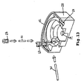
- Thimble-like element 22 ( Figures 8 , 9 , 10 , 17 , 18 , and 19 ) is adapted to surround a portion of a surgeon's finger.
- Thimble-like element 22 is constructed to expose the ventral tactile portions of the distal phalanx of the surgeon's finger, so as to enable the surgeon to tactile sense a body location to be sutured ( Figures 4 , 6 , 8 , 9 , 15 , 17 and 18 ).
- thimble-like element 22 is constructed so as to be mounted over a dorsal side of the distal phalanx of the surgeon's finger, thereby exposing the entire ventral tactile portions of the distal phalanx.
- thimble-like element 22 is constructed so as to fully surround the distal phalanx and expose the tip of the ventral tactile portion of the distal phalanx such that it can be mounted over a ventral side of the distal phalanx of the surgeon's finger and expose the tip of the ventral tactile portion of the distal phalanx.
- Device 20 may further include an adapter 600 insertable between the thimble-like element 22 and the surgeon's finger, so as to adapt the suture device to fingers of different size ( Figures 32a-b ).
- Surgical needle 24 is an ejectable substantially semi-circular needle engaged within a housing 25 being formed within, or connected to, a wall 112 of thimble-like element 22 .
- Wall 112 may be, for example a sidewall ( Figure 1 ) or a front wall ( Figure 2 ) of thimble like element 22 .
- Needle 24 is designed for collecting a surgical suture 26 via a distal portion 28 of needle 24 upon contact with suture 26 and for retaining and guiding suture 26 while suturing.
- Suture 26 is collected retained and guided by, for example, notch 44 of needle 24 .
- the function of notch 44 may be performed equally well by, for example, a hook 46 , at least one arm 48 , or an openable loop 50 at distal end 28 of needle 24 ( Figures 31a, b and c ).
- surgical needle 24 is ejectable in a direction generally perpendicular to a longitudinal axis of thimble like element 22 ( Figures 11-20 ).
- surgical needle 24 travels along at least a portion of a circular path, the path being on a plane which substantially parallels a plane traversing the surgeon's finger from top to bottom ( Figures 11-20 ).
- surgical needle 24 travels along at least a portion of a circular path, the path being on a plane which substantially parallels a plane traversing the surgeon's finger from side to side ( Figures 3-10 ).
- surgical needle 24 travels along at least a portion of a circular path, the path being on a plane which is substantially perpendicular to the longitudinal axis of the surgeon's finger ( Figures 3-10 ).
- Mechanism 30 serves for ejecting surgical needle 24 from housing 25 formed in thimble-like element 22 via an exit point 21 and thereafter withdrawing surgical needle 24 into housing 25 of thimble-like element 22 via an entry point 23 , so as to place a suture.
- Distal portion 28 of needle 24 collects suture 26 after passing through entry point 23 by engaging a loop 110 of suture 26 in a notch 44 formed at a distal end of needle 24 .
- needle 24 is then withdrawn back through entry point 23 and into exit point 21 placing a suture.
- Mechanism 30 may be, for example, a belt actuated mechanism, a gear actuated mechanism or a combined gear and belt actuated mechanism (as depicted in the drawings). More details of the alternative preferred embodiments of mechanism 30 are further described hereinbelow.
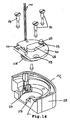
- finger-guided suture device 20 further include surgical suture 26 formed with loop 110 ( Figures 5 and 16 ) for collection by surgical needle 24 .
- Loop 110 is contained within a cartridge 32 which serves for holding surgical suture 26 and for presenting it for collection via notch 44 formed at distal portion 28 of surgical needle 24 .
- Cartridge 32 ( Figures 6 and 17 ) includes at least one mechanism designed and constructed, so as to maintain a predetermined tension of surgical suture 26.
- a mechanism which is suitable for maintaining such a predetermined tension may be, for example, at least one piece of flexible material 36 containing at least one hole 38 through which surgical suture 26 passes.
- a single piece of flexible material 36 containing two holes 38 ( Figure 5 ) or a pair of pieces of flexible material 36 each containing one hole 38 ( Figure 16 ) can, for example, be employed.
- Flexible material 36 may be, for example, silicon, latex, rubber, fabric, or fabric with an eyelet.
- An eyelet may be constructed of material including, but not limited to, silicon, latex, rubber or fabric. Friction on suture 26 as it passes through cartridge 32 is reduced by rounding of corners 35 within cartridge 32.
- Cartridge 32 is covered with a cover 29 and affixed to housing 25 of device 20 by bolts 114 which pass through bolt holes 113 ( Figures 6 and 17 ).
- bolts are pictured in all figures, other connecting means, including but not limited to, screws, rivets, nails, pins, glue, soldering, heat pressing and/or welding might be employed to assemble components of device 20 without substantially affecting its functions.
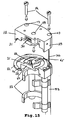
- Drive mechanism 30 which serves for driving needle 24 includes a first portion 54 ( Figures 3 , 7 , 12 and 14 ) engaged within housing 25 .
- First portion 54 is in contact with needle 24 .
- Drive mechanism 30 also includes a second, remote, portion 56 ( Figures 1 and 2 ) extending out of the patient's body and which is operable by a free hand of the surgeon so as to eject needle 24 from thimble-like element 22.
- Pipe or tube 53 containing cable 100 operatively connects first portion 54 to second portion 56 .
- first portion 54 of mechanism 30 includes a rotatable wheel 58 having an axle 60.
- Axle 60 serves for engaging surgical needle 24 and imparting thereto a rotational motion 62 in at least one direction.
- Axle 60 fits into axle seats 59 ( Figure 4 ).
- Cable 100 is contained in pipe 53 which is seated in pipe seat 55 .
- Pulley 27 serves to reduce friction on cable 100 .
- needle 24 includes a mechanism 64 for engaging rotatable wheel. 58 .
- first portion 54 of mechanism 30 also includes a locking piece 66 for insuring that surgical needle 24 and rotatable wheel 58 remain engaged.
- first portion 54 of mechanism 30 includes rotatable wheel 58 which has mechanism 64 which serves for engaging an axle 71 of a drive arm 68 and imparting a rotational motion, as indicated by 62 , in at least one direction thereto.
- Drive arm 68 is designed and constructed to be engageable by both rotatable wheel 58 and needle 24 .
- a needle engaging piece 69 fits into a mechanism 65 which serves for engaging drive arm 68 of needle 24 and imparts a rotational motion, as indicated at 62 , of rotatable wheel 58 in at least one direction to surgical needle 24 .
- a disk 70 ensures that needle 24 , drive arm 68 and rotatable wheel 58 remain engaged.
- cable 100 passes over a pair of pulleys 27 mounted on a pair of axles 31 in housing 25 ( Figure 13 ). Needle 24 rotates about axle 60 ( Figure 11 ) and has a range of motion which is restricted by a stopping piece 67 ( Figure 12 ). Again, pipe 53 serves to contain cable 100.
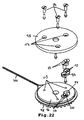
- Remote portion 56 ( Figures 21-30 ) of drive mechanism 30 includes a hand operable actuator 72 ( Figure 21 ) for operating drive mechanism 30 .
- Remote portion 56 also includes a drive housing 76 for containing at least a portion 74 of drive mechanism 30, and at least a portion 74 ( Figure 22 ) of drive mechanism 30.
- Drive mechanism 30 functions to impart a rotational motion in at least one direction to needle 24.
- Hand operable actuator 72 of remote portion 56 of drive mechanism 30 includes a handle 78 for engaging at least one finger of the free hand of the surgeon.
- Actuator 72 of remote portion 56 also includes an extending piece 80 containing a plurality of arcuate teeth 82 . Extending piece 80 is movable through drive housing 76 by means of pressure applied to handle 78 by at least one finger of the free hand of the surgeon.
- Actuator 72 of remote portion 56 also includes a pressure sensitive spring 84 and a brake handle 86 .
- Brake handle 86 is operable in a first direction by pressure sensitive spring 84 and in a second direction by the at least one finger of the free hand of the surgeon.
- Remote portion 56 of drive mechanism 30 includes plurality of arcuate teeth 82 deployed in a linear arrangement along an extending piece 80 of handle 78 .
- Drive mechanism 30 further includes a first gear 92 with a first circular arrangement of arcuate teeth 94 .
- First circular arrangement of arcuate teeth 94 serves for engaging plurality of arcuate teeth 82 along extending piece 80 . Linear displacement of extending piece 80 is therefore translated into rotational motion of first gear 92 .
- Remote portion 56 of drive mechanism 30 further includes a second gear 96 .
- Second gear 96 includes a second circular arrangement of arcuate teeth 98 for engaging first circular arrangement of arcuate teeth 94 of first gear 92 .
- second circular arrangement of arcuate teeth 98 is actually two concentric circular arrangements of arcuate teeth, although a single circular arrangement of arcuate teeth might be employed without significantly affecting the performance of device 20 .
- a cover 95 covers second gear 96 .
- Cable 100 is fitted around at least a portion of second gear 96 and is fixed to gear 96 in at least one point by a cable holding piece 97 , placed in a holding piece well 99 and secured via bolts 114 which fit into bolt holes 113. Therefore, rotational motion of first gear 92 causes rotational motion of second gear 96 .
- Remote portion 56 of drive mechanism 30 further includes at least a portion of cable 100 in contact with at least one point on second gear 96 , such that rotational motion of second gear 96 is translated to linear motion of cable 100.
- First gear 92 and second gear 96 are fitted on, and rotate about, axles 91 and 101 , respectively ( Figure 23 ).
- remote portion 56 of drive mechanism 30 further includes a ratchet 102 for alternately engaging and releasing at least one arcuate tooth 94 of the first gear 92.
- Remote portion 56 of drive mechanism 30 further includes a ratchet control arm 104 for alternately engaging and releasing ratchet 102 .
- Remote portion 56 of drive mechanism 30 further includes a brake handle 86 for alternately operating the ratchet control arm. These components are operatively arranged so that when brake handle 86 operates ratchet control arm 104 , ratchet control arm 104 releases ratchet 102 , ratchet 102 engages at least one arcuate tooth 94 of first gear 92 and preventing it from rotating.
- a typical sequence of events during use of device 20 includes placement of thimble like element 22 onto a finger of a first hand of a surgeon and insertion of the finger bearing device 20 into an intrabody location. After tactile sensing, the surgeon aligns device 20 with a location for suture placement. At this time the surgeon places at least one finger of a second hand into handle 78 of actuator 72 while stabilizing actuator 72 with one or more additional fingers placed in additional loops 83 . Referring now to Figure 28 , the surgeon then begins to move handle 78 towards housing 73 so that arcuate teeth 82 of extending piece 80 engage arcuate teeth 94 of first gear 92 . First gear rotates in a clockwise direction, thereby rotating second gear 96 (covered by cover 95 ).
- ratchet control arm 104 overcomes the tension of control arm spring 107 so that first engagement point 77 releases second engagement point 79 ( Figure 29 ).
- ratchet spring 109 moves ratchet 102 so that third engagement point 81 engages at least one tooth 94 of first gear 92 thereby arresting it. This prevents further motion of second gear 96 , cable 100 , rotatable wheel 58 and needle 24 .
- first gear 92 imparts a clockwise rotational motion to second gear 96 which, as is mentioned above, is covered by cover 95.
- the clockwise rotational motion of second gear 96 is translated to linear displacement of cable 100 in a second direction. This reverses the direction of rotational motion 62 of rotatable wheel 58 causing withdrawal of needle 24 .
- notch 44 collects suture 26 as needle 24 is withdrawn through entry point 23 and into exit point 21 , thereby placing a suture.
- finger-guided suture device 20 further includes at least one optical head 700 engaged by thimble-like element 22 thereof.
- Optical head 700 communicates with a monitor or any other display for presenting the surgeon with details of the path to the body location to be treated or the treated body location itself prior, during or after treatment.
- Optical head 700 can include a miniaturized camera and/or preferably a bundle of optic-fibers to generate an image which is representable on a monitor or any other display.
- optical head 700 can include one or more optical elements such as, but not limited to, lenses, prisms, reflectors and the like. Of particular interest is a fish-eye lens which can be used to provide a larger field of view for optical head 700 .
- optical head 700 includes a lens for focusing imagery data onto a bundle of fiber optics which transmit the imagery data to a sensor, such as, but not limited to, a camera which is remote and connectable to the device or instrument. This feature is of importance in cases where the device is of a disposal type.
- Finger-guided suture device 20 may further include a reporting mechanism for reporting a situation such as a full ejection of the substantially semi-circular surgical needle 24 , a full withdrawal of the substantially semi-circular surgical needle 24 , a degree of ejection of the substantially semi-circular surgical needle 24 or a degree of withdrawal of the substantially semi-circular surgical needle 24 .
- the reporting mechanism may be, for example, optical head 700 .
- the suture device described hereinabove enjoy several important advantages over the designs described in the background section since it provides: (i) complete control of the needle motion at any time, i.e., the surgeon can retrieve the needle back to its housing at any time of the procedure without loosing the needle in the tissue; (ii) the possibility to use different types of suture material with the same needle which is realized in this case since the suture is not attached to the needle, thus allowing to load different types of suture into the cartridge and use the same needle; (iii) optimal security to the surgeon during the needle motion; (iv) optimal security to the patient since the depth of the needle bite is fixed in advanced and can not be change during the needle motion; and (v) optimal suture placement since the size of the surgical bite is fixed and known in advanced, thus the suture material can be placed in an accurate way.
- suturing devices according to the invention will be described and explained herein as being applied in a novel procedure for bladder-neck suspension used for treatment of urinary incontinence (genuine stress urinary incontinence - GSUI) in females, it is also suitable for application in, e.g., sacro-spinous ligament fixation, and for anchoring suture material, even in conventional transabdominal pelvic surgery, where in obese patients exposure is limited and the surgeon has to rely on palpation of pelvic structures.
- the procedure is a surgical treatment of genuine stress urinary incontinence (GSUI) in females, and aims at the correction of the suspension of the anatomical area defined as the "bladder neck", i.e., returning the bladder neck to its former, normal position.
- GSUI stress urinary incontinence
- Such procedures are known, the one having the highest success rate being the Burch Colposuspension, in which the pelvic fascia and vaginal wall lateral to the urethra is suspended to Cooper's ligament. While this procedure indeed appears to be the most promising, it still is a transabdominal method, requiring general anesthesia, an extensive abdominal incision and hospitalization.
- the surgical correction can be performed by constriction of the anal opening which might cause chronic defecation dysfunction or through an abdominal approach.
- the upper part of the rectum is anchored to the Sacral bone.
- any of the suturing devices of the present invention can render the anchoring procedure in the small and deep pelvic area an easier and shorter process, avoiding the need of extensive dissection to expose the correct anatomical target.
- Another procedure that will benefit from the use of the suturing devices of the present invention is in the case of treating Esophageal reflux in children.
- the surgical correction is based on reconstruction of a one way valve mechanism around the Esophagus. Passing a "Vessel loop", i.e., a thin rubber band, around the Esophagus prevents the reflux.
- Any of the suturing devices of the present invention can replace the need for dissection of the Esophagus and makes it easy to pass the Vessel loop behind the esophagus in a short and safe fashion.
- vaginal prolapse is a result of weakening of connective tissue support to the vaginal vault apex.
- One of the most common surgical techniques used to correct vaginal prolapse includes tying the upper part of the vagina to a connective tissue condensation stretched from both sides of the sacrum. This anatomical structure is called The Sacrospinous Ligament, and the procedure is called Sacrospinous Ligament Fixation. In order to perform the procedure, the surgeon needs to open the posterior wall of the vagina and enter to a space beside the rectum to reach the ligament.
- a surgical thread is anchored to the ligament and is thereafter tied to the vagina, thus fixing the upper part of the vagina to the ligament. Since the location of the ligament is deep in the pelvic hole, the surgeon needs to perform extensive dissection to expose the ligament and place the suture material under direct visualization using long instruments. However, palpation of the ligament is easy and within reach of the surgeon's finger. Mounting any of the suturing devices according to the present invention over the surgeon's finger thus enables the surgeon to place the suture in the correct location, avoiding the need for extensive dissection, reducing blood lose and shortening operation time. Palpation of the correct location makes the procedure even safer by reducing the risk of injury to pelvic blood vessels behind certain areas of the ligament.
- the present treatment involves placement of sutures into the cervix after conception, so as to reduce the size of the opening. These sutures are inserted blindly by a needle held by the fingers. Any of the suturing devices according to the present invention can be used instead.
Landscapes
- Health & Medical Sciences (AREA)
- Life Sciences & Earth Sciences (AREA)
- Surgery (AREA)
- Molecular Biology (AREA)
- General Health & Medical Sciences (AREA)
- Biomedical Technology (AREA)
- Heart & Thoracic Surgery (AREA)
- Medical Informatics (AREA)
- Nuclear Medicine, Radiotherapy & Molecular Imaging (AREA)
- Animal Behavior & Ethology (AREA)
- Engineering & Computer Science (AREA)
- Public Health (AREA)
- Veterinary Medicine (AREA)
- Surgical Instruments (AREA)
- Yarns And Mechanical Finishing Of Yarns Or Ropes (AREA)
- Materials For Medical Uses (AREA)
- Acyclic And Carbocyclic Compounds In Medicinal Compositions (AREA)
- Transition And Organic Metals Composition Catalysts For Addition Polymerization (AREA)
Claims (30)
- Fingergeführtes chirurgisches Nähgerät (20), das aufweist:ein ringartiges Element (22), das so ausgebildet ist, dass es einen Teil des Fingers eines Chirurgen umgibt,eine ausfahrbare, im Wesentlichen halbkreisförmige chirurgische Nadel (24), die in ein Gehäuse (25) eingesetzt ist, das in einer Wand (112) des ringartigen Elements (22) ausgebildet oder mit ihr verbunden ist,
undeinen Mechanismus (30) zum Ausfahren der chirurgischen Nadel (24) aus dem ringartigen Element (22) und zum anschließenden Zurückziehen der chirurgischen Nadel (24) in das ringartige Element (22), um so eine Naht zu setzen,dadurch gekennzeichnet, dass der distale Teil (28) der chirurgischen Nadel (24) so ausgebildet ist, dass er ein chirurgisches Nahtmaterial (26), nachdem er damit in Kontakt gekommen ist, fängt, und so ausgebildet ist, dass er das chirurgische Nahtmaterial (26) während des Nähens festhält und führt. - Fingergeführtes chirurgisches Nähgerät (20) nach Anspruch 1, bei dem das ringartige Element (22) so ausgebildet und gebaut ist, dass die ventralen taktilen Bereiche des distalen Fingergliedes des Fingers des Chirurgen frei liegen, so dass der Chirurg eine zu vernähende Stelle des Körpers taktil erfühlen kann.
- Fingergeführtes chirurgisches Nähgerät (20) nach Anspruch 1, das ferner einen Einsatz aufweist, der das chirurgische Nahtmaterial (26) aufnimmt und es zum Fangen durch den distalen Teil (28) der chirurgischen Nadel (24) vorlegt.
- Fingergeführtes chirurgisches Nähgerät (20) nach Anspruch 3, bei dem der Einsatz mindestens einen Mechanismus aufweist, der so ausgebildet und gebaut ist, dass er eine vorgegebene Spannung des chirurgischen Nahtmaterials (26) aufrechterhält.
- Fingergeführtes chirurgisches Nähgerät (20) nach Anspruch 4, bei dem der mindestens eine Mechanismus, der so ausgebildet und gebaut ist, dass er eine vorgegebene Spannung des chirurgischen Nahtmaterials (26) aufrechterhält, mindestens ein Teil aus einem flexiblen Material (36) aufweist, das mindestens ein Loch besitzt, durch welches das chirurgische Nahtmaterial (26) läuft.
- Fingergeführtes chirurgisches Nähgerät (20) nach Anspruch 5, bei dem das mindestens eine Teil aus flexiblem Material (36), das mindestens ein Loch besitzt, aus der Gruppe ausgewählt ist, die besteht aus einem einzigen Teil aus flexiblem Material (36), das zwei Löcher besitzt, und zwei Teilen aus flexiblem Material (36), die jeweils ein Loch besitzen.
- Fingergeführtes chirurgisches Nähgerät (20) nach Anspruch 5, bei dem das flexible Material (36) aus der Gruppe ausgewählt ist, die besteht aus Silicon, Latex, Kautschuk, einem Gewebe und einem Gewebe mit einer Öse.
- Fingergeführtes chirurgisches Nähgerät (20) nach Anspruch 7, bei dem die Öse aus einem Material ausgebildet ist, das aus der Gruppe ausgewählt ist, die besteht aus Silicon, Latex, Kautschuk und einem Gewebe.
- Fingergeführtes chirurgisches Nähgerät (20) nach Anspruch 1, bei dem der Mechanismus (30) zum Ausfahren der chirurgischen Nadel (24) aus dem ringartigen Element (22) und zum Zurückziehen der chirurgischen Nadel (24) in das ringartige Element (22) aus der Gruppe ausgewählt ist, die besteht aus einem riemenbetätigten Mechanismus, einem getriebebetätigten Mechanismus und einem kombinierten getriebebetätigten und riemenbetätigten Mechanismus.
- Fingergeführtes chirurgisches Nähgerät (20) nach Anspruch 1, bei dem die chirurgische Nadel (24) in ihrer Ausbildung ein Merkmal aufweist, das aus der Gruppe ausgewählt ist, die besteht aus einer Einkerbung, einem Haken, mindestens einem Arm und einem zu öffnenden Öhr an ihrem distalen Ende.
- Fingergeführtes chirurgisches Nähgerät (20) nach Anspruch 1, das ferner einen Adapter (600) aufweist, der zwischen das ringartige Element (22) und den Finger des Chirurgen einschiebbar ist, um das Nähgerät (20) an Finger unterschiedlicher Dicke anzupassen.
- Fingergeführtes chirurgisches Nähgerät (20) nach Anspruch 1, bei dem der Mechanismus (30) einen ersten Abschnitt, der mit dem Gehäuse (25) in Eingriff steht, und einen zweiten, davon entfernt liegenden Abschnitt aufweist, der sich aus dem Körper des Patienten heraus erstreckt und der durch eine freie Hand des Chirurgen so zu betätigen ist, dass die chirurgische Nadel (24) aus dem ringartigen Element (22) ausgefahren wird.
- Fingergeführtes chirurgisches Nähgerät (20) nach Anspruch 12, bei dem der erste Abschnitt des Mechanismus (30) ein drehbares Rad mit einer Achse aufweist, wobei die Achse zum Eingriff mit der chirurgischen Nadel (24) dient und ihr eine Drehbewegung in mindestens einer Richtung vermittelt, wobei die chirurgische Nadel (24) einen Mechanismus zum Eingriff mit dem drehbaren Rad und ein Verriegelungsteil aufweist, um sicherzustellen, dass die chirurgische Nadel (24) und das drehbare Rad in Eingriff bleiben.
- Fingergeführtes chirurgisches Nähgerät (20) nach Anspruch 12, bei dem der erste Abschnitt des Mechanismus (30) ein drehbares Rad aufweist, das einen Mechanismus zum Eingriff mit einem Antriebsarm besitzt und ihm eine Drehbewegung in mindestens einer Richtung vermittelt, wobei der Antriebsarm so ausgebildet und gebaut ist, dass er mit dem drehbaren Rad und der chirurgischen Nadel (24) in Eingriff zu bringen ist und der chirurgischen Nadel (24) eine Drehbewegung des drehbaren Rades in mindestens einer Richtung vermittelt, wobei die chirurgische Nadel (24) ferner einen Mechanismus zum Eingriff mit dem Antriebsarm und eine Scheibe aufweist, um sicherzustellen, dass die chirurgische Nadel (24), der Antriebsarm und das drehbare Rad in Eingriff bleiben.
- Fingergeführtes chirurgisches Nähgerät (20) nach Anspruch 12, bei dem der entfernt liegende Abschnitt, der sich aus dem Körper des Patienten heraus erstreckt und der durch eine freie Hand des Chirurgen so zu betätigen ist, dass die chirurgische Nadel (24) aus dem ringartigen Element (22) ausgefahren wird, aufweist:ein mit der Hand betätigbares Bedienteil, das so ausgebildet und gebaut ist, dass damit ein Antriebsmechanismus zu betätigen ist,ein Antriebsgehäuse zur Aufnahme mindestens eines Teils des Antriebsmechanismus
undmindestens einen Teil des Antriebsmechanismus, wobei der Antriebsmechanismus dazu dient, der chirurgischen Nadel (24) eine Drehbewegung in mindestens einer Richtung zu vermitteln. - Fingergeführtes chirurgisches Nähgerät (20) nach Anspruch 15, bei dem das mit der Hand betätigbare Bedienteil des entfernt liegenden Abschnitts aufweist:einen Handgriff, der mit mindestens einem Finger der freien Hand des Chirurgen zu ergreifen ist,ein Verlängerungsteil, das eine Vielzahl bogenförmiger Zähne aufweist und durch das Antriebsgehäuse bewegbar ist,eine Druckfeder
undeinen Bremsgriff, wobei der Bremsgriff durch die Druckfeder in einer ersten Richtung und durch den mindestens einen Finger der freien Hand des Chirurgen in einer zweiten Richtung betätigbar ist. - Fingergeführtes chirurgisches Nähgerät (20) nach Anspruch 15, bei dem der Antriebsmechanismus aufweist:eine Vielzahl bogenförmiger Zähne, die längs eines Verlängerungsteils eines Handgriffes in einer linearen Anordnung ausgebildet sind,ein erstes Zahnrad mit einer ersten kreisförmigen Anordnung bogenförmiger Zähne, wobei die erste kreisförmige Anordnung bogenförmiger Zähne zum Eingriff mit der Vielzahl bogenförmiger Zähne, die längs des Verlängerungsteils in der linearen Anordnung ausgebildet sind, in der Weise vorgesehen ist, dass eine lineare Verschiebung des Verlängerungsteils in eine Drehbewegung des ersten Zahnrads umgesetzt wird,ein zweites Zahnrad, das eine zweite kreisförmige Anordnung bogenförmiger Zähne aufweist, wobei die bogenförmigen Zähne des zweiten Zahnrads zum Eingriff mit der ersten kreisförmigen Anordnung bogenförmiger Zähne des ersten Zahnrads in der Weise vorgesehen sind, dass die Drehbewegung des ersten Zahnrads eine Drehbewegung des zweiten Zahnrads bewirkt,
undein Seil im Kontakt mit mindestens einem Punkt an dem zweiten Zahnrad, so dass die Drehbewegung des zweiten Zahnrads in eine lineare Bewegung zumindest eines Teils des Seils umgesetzt wird. - Fingergeführtes chirurgisches Nähgerät (20) nach Anspruch 17, bei dem der Antriebsmechanismus ferner aufweist:eine Sperrklinke zum abwechselnden Eingriff in mindestens einen bogenförmigen Zahn des ersten Zahnrads und zu dessen Freigabe,einen Sperrklinken-Steuerarm zum abwechselnden Eingriff in die Sperrklinke und zu ihrer Freigabe,einen Bremsgriff zur abwechselnden Betätigung des Sperrklinken-Steuerarms,wobei, wenn der Bremsgriff den Sperrklinken-Steuerarm betätigt, der Sperrklinken-Steuerarm die Sperrklinke freigibt, die Sperrklinke in den mindestens einen bogenförmigen Zahn des ersten Zahnrads eingreift und das erste Zahnrad an der Drehung gehindert wird, während, wenn der Bremsgriff den Sperrklinken-Steuerarm nicht betätigt, der Sperrklinken-Steuerarm in die Sperrklinke eingreift, die Sperrklinke den mindestens einen bogenförmigen Zahn des ersten Zahnrads freigibt und das erste Zahnrad sich frei drehen kann.
- Fingergeführtes chirurgisches Nähgerät (20) nach Anspruch 1, bei dem das ringartige Element (22) so gebaut ist, dass es über eine dorsale Seite des distalen Fingergliedes des Fingers des Chirurgen aufgesteckt werden kann, wodurch die gesamten ventralen taktilen Bereiche des distalen Fingergliedes freiliegen.
- Fingergeführtes chirurgisches Nähgerät (20) nach Anspruch 1, bei dem das ringartige Element (22) so gebaut ist, dass es das distale Fingerglied des Fingers vollständig umgibt und die Spitze des ventralen taktilen Bereichs des distalen Fingergliedes freiliegt.
- Fingergeführtes chirurgisches Nähgerät (20) nach Anspruch 1, bei dem das ringartige Element (22) so gebaut ist, dass es über eine ventrale Seite des distalen Fingergliedes des Fingers des Chirurgen aufgesteckt werden kann und die Spitze des ventralen taktilen Bereichs des distalen Fingergliedes freiliegt.
- Fingergeführtes chirurgisches Nähgerät (20) nach Anspruch 1, bei dem die chirurgische Nadel (24) in einer Richtung ausfahrbar ist, die allgemein senkrecht zu einer Längsachse des ringartigen Elements (22) ist.
- Fingergeführtes chirurgisches Nähgerät (20) nach Anspruch 1, bei dem sich die chirurgische Nadel (24) längs zumindest eines Teils einer kreisförmigen Bahn bewegt, wobei sich die Bahn auf einer Ebene befindet, die im Wesentlichen parallel zu einer Ebene liegt, die von oben nach unten durch den Finger des Chirurgen verläuft.
- Fingergeführtes chirurgisches Nähgerät (20) nach Anspruch 1, bei dem sich die chirurgische Nadel (24) längs zumindest eines Teils einer kreisförmigen Bahn bewegt, wobei sich die Bahn auf einer Ebene befindet, die im Wesentlichen parallel zu einer Ebene liegt, die von Seite zu Seite durch den Finger des Chirurgen verläuft.
- Fingergeführtes chirurgisches Nähgerät (20) nach Anspruch 1, bei dem sich die chirurgische Nadel (24) längs zumindest eines Teils einer kreisförmigen Bahn bewegt, wobei sich die Bahn auf einer Ebene befindet, die im Wesentlichen senkrecht zur Längsachse des Fingers des Chirurgen verläuft.
- Fingergeführtes chirurgisches Nähgerät (20) nach Anspruch 1, das ferner einen Optikkopf aufweist, der in dem ringartigen Element (22) aufgenommen ist.
- Fingergeführtes chirurgisches Nähgerät (20) nach Anspruch 1, das ferner das chirurgische Nahtmaterial (26) aufweist, das mit einer Schlinge zum Fangen durch die chirurgische Nadel (24) versehen ist.
- Fingergeführtes chirurgisches Nähgerät (20) nach Anspruch 1, bei dem es sich bei der Wand um eine Seitenwand des ringartigen Elements (22) handelt.
- Fingergeführtes chirurgisches Nähgerät (20) nach Anspruch 1, bei dem es sich bei der Wand um eine Vorderwand des ringartigen Elements (22) handelt.
- Fingergeführtes chirurgisches Nähgerät (20) nach Anspruch 1, die ferner einen Anzeigemechanismus zur Anzeige mindestens einer Situation aufweist, die aus der Gruppe ausgewählt ist, die besteht aus einem vollständigen Ausfahren der im Wesentlichen halbkreisförmigen chirurgischen Nadel (24), einem vollständigen Zurückziehen der im Wesentlichen halbkreisförmigen chirurgischen Nadel (24), einem Grad des Ausfahrens der im Wesentlichen halbkreisförmigen chirurgischen Nadel (24) und einem Grad des Zurückziehens der im Wesentlichen halbkreisförmigen chirurgischen Nadel (24).
Priority Applications (1)
| Application Number | Priority Date | Filing Date | Title |
|---|---|---|---|
| EP10180795.6A EP2289426B1 (de) | 2000-05-25 | 2001-05-24 | Fingergeführtes vernähgerät |
Applications Claiming Priority (3)
| Application Number | Priority Date | Filing Date | Title |
|---|---|---|---|
| US09/577,974 US6475135B1 (en) | 2000-05-25 | 2000-05-25 | Finger-guided suture device |
| US577974 | 2000-05-25 | ||
| PCT/IL2001/000485 WO2001089360A2 (en) | 2000-05-25 | 2001-05-24 | Finger-guided suture device |
Related Child Applications (2)
| Application Number | Title | Priority Date | Filing Date |
|---|---|---|---|
| EP10180795.6A Division EP2289426B1 (de) | 2000-05-25 | 2001-05-24 | Fingergeführtes vernähgerät |
| EP10180795.6 Division-Into | 2010-09-28 |
Publications (3)
| Publication Number | Publication Date |
|---|---|
| EP1284659A2 EP1284659A2 (de) | 2003-02-26 |
| EP1284659A4 EP1284659A4 (de) | 2009-09-16 |
| EP1284659B1 true EP1284659B1 (de) | 2011-05-04 |
Family
ID=24310926
Family Applications (2)
| Application Number | Title | Priority Date | Filing Date |
|---|---|---|---|
| EP10180795.6A Expired - Lifetime EP2289426B1 (de) | 2000-05-25 | 2001-05-24 | Fingergeführtes vernähgerät |
| EP01936771A Expired - Lifetime EP1284659B1 (de) | 2000-05-25 | 2001-05-24 | Fingergeführtes chirurgisches vernähgerät |
Family Applications Before (1)
| Application Number | Title | Priority Date | Filing Date |
|---|---|---|---|
| EP10180795.6A Expired - Lifetime EP2289426B1 (de) | 2000-05-25 | 2001-05-24 | Fingergeführtes vernähgerät |
Country Status (10)
| Country | Link |
|---|---|
| US (2) | US6475135B1 (de) |
| EP (2) | EP2289426B1 (de) |
| AT (1) | ATE507779T1 (de) |
| AU (1) | AU6263001A (de) |
| CA (1) | CA2410365A1 (de) |
| DE (1) | DE60144559D1 (de) |
| DK (1) | DK1284659T3 (de) |
| ES (1) | ES2366182T3 (de) |
| IL (1) | IL153051A0 (de) |
| WO (1) | WO2001089360A2 (de) |
Families Citing this family (77)
| Publication number | Priority date | Publication date | Assignee | Title |
|---|---|---|---|---|
| US6475135B1 (en) * | 2000-05-25 | 2002-11-05 | Urogyn Ltd. | Finger-guided suture device |
| US6997932B2 (en) * | 2001-05-21 | 2006-02-14 | Boston Scientific Scimed, Inc. | Suture passer |
| US6719764B1 (en) | 2001-08-24 | 2004-04-13 | Scimed Life Systems, Inc. | Forward deploying suturing device and methods of use |
| US6984237B2 (en) | 2002-05-22 | 2006-01-10 | Orthopaedic Biosystems Ltd., Inc. | Suture passing surgical instrument |
| US6936054B2 (en) | 2002-07-22 | 2005-08-30 | Boston Scientific Scimed, Inc. | Placing sutures |
| AU2003270549A1 (en) * | 2002-09-09 | 2004-03-29 | Brian Kelleher | Device and method for endoluminal therapy |
| US7338502B2 (en) * | 2002-12-18 | 2008-03-04 | Rosenblatt Associates, Llc | Systems and methods for soft tissue reconstruction |
| US20040193211A1 (en) * | 2003-02-14 | 2004-09-30 | Voegele James W. | Fingertip surgical instruments |
| US20040199204A1 (en) * | 2003-02-14 | 2004-10-07 | Voegele James W. | Multifunctional surgical instrument |
| US20040225217A1 (en) * | 2003-02-14 | 2004-11-11 | Voegele James W. | Fingertip ultrasound medical instrument |
| NL1025852C2 (nl) * | 2004-03-31 | 2005-10-03 | Glengowan B V | Chirurgisch instrument. |
| US20080312669A1 (en) * | 2004-03-31 | 2008-12-18 | Vries Luc De | Surgical instrument and method |
| WO2006007399A1 (en) | 2004-06-16 | 2006-01-19 | Smith & Nephew, Inc. | Suture passing |
| US7976559B2 (en) * | 2004-11-04 | 2011-07-12 | Dynamic Surgical Inventions, Llc | Articulated surgical probe and method for use |
| US7803142B2 (en) | 2005-02-02 | 2010-09-28 | Summit Access Llc | Microtaper needle and method of use |
| US8709018B2 (en) * | 2005-09-16 | 2014-04-29 | Applied Medical Technology, Inc. | Non-balloon low profile feed device with insertion/removal tool |
| US20070123904A1 (en) * | 2005-10-31 | 2007-05-31 | Depuy Spine, Inc. | Distraction instrument and method for distracting an intervertebral site |
| US20070239208A1 (en) * | 2006-04-05 | 2007-10-11 | Crawford Bruce S | Surgical implantation device and method |
| GB2438594B (en) * | 2006-06-01 | 2011-02-16 | Abdelfattah Amin Taha | Cervical needle |
| US20090192530A1 (en) | 2008-01-29 | 2009-07-30 | Insightra Medical, Inc. | Fortified mesh for tissue repair |
| US8308725B2 (en) * | 2007-03-20 | 2012-11-13 | Minos Medical | Reverse sealing and dissection instrument |
| BRPI0701767A2 (pt) * | 2007-07-20 | 2009-03-10 | Marcial Trilha Jr | sistema de sutura remotamente operado |
| US9320587B2 (en) | 2007-11-02 | 2016-04-26 | Cornell University | Method and apparatus for endoscopically treating rectal prolapse |
| US8430890B2 (en) * | 2007-11-02 | 2013-04-30 | Jeffrey Milsom | Method and apparatus for endoscopically treating rectal prolapse |
| US20100305566A1 (en) * | 2007-11-30 | 2010-12-02 | New England Assoication Of Gynecologic Laparoscopists, Llp | Transcervical excision and removal of tissue |
| US9439746B2 (en) * | 2007-12-13 | 2016-09-13 | Insightra Medical, Inc. | Methods and apparatus for treating ventral wall hernia |
| US8940017B2 (en) | 2008-07-31 | 2015-01-27 | Insightra Medical, Inc. | Implant for hernia repair |
| WO2009102945A2 (en) * | 2008-02-14 | 2009-08-20 | Brown Robert C | Method for treating stress urinary incontinence and symptomatic pelvic relaxation |
| DK200970073A (en) * | 2009-07-22 | 2011-01-23 | Coloplast As | Suturing system and assembly |
| US8465503B2 (en) * | 2009-10-19 | 2013-06-18 | Coloplast A/S | Finger guided suture fixation system |
| DK201070272A (en) * | 2009-10-19 | 2011-04-20 | Coloplast As | Finger guided suture fixation system |
| US8758371B2 (en) * | 2009-10-20 | 2014-06-24 | Coloplast A/S | Method of fixing a suture to tissue |
| DK201070270A (en) * | 2009-10-19 | 2011-04-20 | Coloplast As | Finger guided suture fixation system |
| WO2011047685A2 (en) | 2009-10-19 | 2011-04-28 | Coloplast A/S | Finger guided suture fixation system |
| US8257366B2 (en) * | 2010-02-08 | 2012-09-04 | Coloplast A/S | Digital suture fixation system |
| US20110196389A1 (en) * | 2010-02-09 | 2011-08-11 | Coloplast A/S | Digital suture fixation system |
| US8936611B2 (en) | 2010-05-27 | 2015-01-20 | Raptor Surgical, LLC | Apparatus and methods for achilles tendon repair |
| US8556916B2 (en) | 2011-02-14 | 2013-10-15 | Smith & Nephew, Inc. | Method and device for suture manipulation |
| US20120240378A1 (en) * | 2011-03-24 | 2012-09-27 | Boston Scientific Scimed, Inc. | Loader for implant delivery tools and methods of using the same |
| US9301825B2 (en) | 2011-07-06 | 2016-04-05 | Boston Scientific Scimed, Inc. | Bodily implants formed from different materials |
| US9357997B2 (en) | 2011-07-08 | 2016-06-07 | Smith & Nephew, Inc. | Suture passer and method |
| US8882834B2 (en) | 2011-07-08 | 2014-11-11 | Smith & Nephew, Inc. | Soft tissue repair |
| US8951263B2 (en) | 2011-07-08 | 2015-02-10 | Smith & Nephew, Inc. | Orthopedic suture passer and method |
| US8888849B2 (en) | 2011-07-08 | 2014-11-18 | Smith & Nephew, Inc. | Soft tissue repair |
| US8801727B2 (en) | 2011-07-08 | 2014-08-12 | Smith & Nephew, Inc. | Orthopedic suture passer and method |
| US9662105B2 (en) | 2011-07-08 | 2017-05-30 | Smith & Nephew, Inc. | Suture passer and method |
| US8992550B2 (en) | 2011-07-20 | 2015-03-31 | Coloplast A/S | Suture system with capsule eyelet providing multiple suture tissue fixation |
| US9351721B2 (en) | 2012-02-16 | 2016-05-31 | Coopersurgical, Inc. | Suture passers and related methods |
| US10182843B2 (en) | 2012-03-06 | 2019-01-22 | Phillip A. Williams | Medical device, method and system thereof |
| US9451952B2 (en) * | 2012-03-22 | 2016-09-27 | Boston Scientific Scimed, Inc. | Suturing device |
| WO2013165942A1 (en) | 2012-05-01 | 2013-11-07 | Brigham And Women's Hospital, Inc. | Suturing device for laparoscopic procedures |
| US10799235B2 (en) | 2012-08-16 | 2020-10-13 | Boston Scientific Scimed, Inc. | Suturing device for treament of pelvic floor disorders |
| US9289205B2 (en) | 2012-12-11 | 2016-03-22 | Raptor Surgical, LLC | Systems for soft tissue repair |
| US9173655B2 (en) | 2012-12-13 | 2015-11-03 | Ethicon Endo-Surgery, Inc. | Needle driver and pawl mechanism for circular needle applier |
| US10231728B2 (en) * | 2013-02-15 | 2019-03-19 | Surgimatix, Inc. | Medical fastening device |
| US9125645B1 (en) | 2013-03-11 | 2015-09-08 | Ethicon Endo-Surgery, Inc. | Reciprocating needle drive without cables |
| US9375212B2 (en) | 2014-06-06 | 2016-06-28 | Ethicon Endo-Surgery, Llc | Circular needle applier with cleats |
| USD771811S1 (en) | 2013-03-15 | 2016-11-15 | Ethicon Endo-Surgery, Llc | Suture tray |
| US20150351749A1 (en) | 2014-06-06 | 2015-12-10 | Ethicon Endo-Surgery, Inc. | Needle Cartridge with Moveable Cover |
| WO2015164819A1 (en) | 2014-04-24 | 2015-10-29 | Smith & Nephew, Inc. | Suture passer |
| US9526495B2 (en) | 2014-06-06 | 2016-12-27 | Ethicon Endo-Surgery, Llc | Articulation control for surgical instruments |
| USD745146S1 (en) | 2014-06-06 | 2015-12-08 | Ethicon Endo-Surgery, Inc. | Surgical suturing device |
| US9936943B1 (en) | 2014-08-07 | 2018-04-10 | Nicholas MANCINI | Suture passing surgical device with atraumatic grasper preventing accidental perforations |
| US10022120B2 (en) | 2015-05-26 | 2018-07-17 | Ethicon Llc | Surgical needle with recessed features |
| US11918204B2 (en) | 2015-06-01 | 2024-03-05 | Lsi Solutions, Inc. | Suturing device for minimally invasive surgery and needles and methods thereof |
| CA2990397C (en) * | 2015-06-01 | 2020-03-31 | Jude S. Sauer | Needle for a minimally invasive surgical suturing device |
| US10327756B2 (en) | 2015-06-01 | 2019-06-25 | Lsi Solutions, Inc. | Re-arming apparatus for a minimally invasive surgical suturing device |
| USD800306S1 (en) | 2015-12-10 | 2017-10-17 | Ethicon Llc | Surgical suturing device |
| US10183159B2 (en) | 2015-12-15 | 2019-01-22 | Heartstitch, Inc. | Constriction valve |
| US9662104B1 (en) * | 2015-12-15 | 2017-05-30 | Heartstitch, Inc. | Throw and catch suturing device with a curved needle |
| WO2018081374A1 (en) | 2016-10-31 | 2018-05-03 | Smith & Nephew, Inc. | Suture passer and grasper instrument and method |
| USD865964S1 (en) | 2017-01-05 | 2019-11-05 | Ethicon Llc | Handle for electrosurgical instrument |
| CA3089814A1 (en) | 2018-01-28 | 2019-08-08 | Lsi Solutions, Inc. | Suturing device for minimally invasive surgery and needles and methods thereof |
| CN108354668B (zh) * | 2018-03-16 | 2024-03-15 | 深圳市罗伯医疗科技有限公司 | 一种消化道手术辅助机器人系统 |
| US20210298743A1 (en) * | 2018-07-18 | 2021-09-30 | Atropolos Limited | Device and system for hernia repair |
| USD895112S1 (en) | 2018-11-15 | 2020-09-01 | Ethicon Llc | Laparoscopic bipolar electrosurgical device |
| US11284879B2 (en) | 2018-12-13 | 2022-03-29 | Howmedica Osteonics Corp. | Systems for soft tissue repair |
Family Cites Families (29)
| Publication number | Priority date | Publication date | Assignee | Title |
|---|---|---|---|---|
| US1822330A (en) * | 1930-01-13 | 1931-09-08 | Ainslie George | Suturing instrument |
| US2738790A (en) * | 1954-08-12 | 1956-03-20 | George P Pilling & Son Company | Suturing instrument |
| JPS57170240A (en) * | 1981-04-14 | 1982-10-20 | Janome Sewing Machine Co Ltd | Suturing stitch constitution by suturing device for operation |
| US4726371A (en) | 1982-02-09 | 1988-02-23 | Gibbens Everett N | Surgical cutting instrument |
| US5112344A (en) * | 1988-10-04 | 1992-05-12 | Petros Peter E | Surgical instrument and method of utilization of such |
| US5097848A (en) * | 1988-10-11 | 1992-03-24 | Schwarz Gerald R | Incontinence bladder control method and apparatus |
| US5013292A (en) * | 1989-02-24 | 1991-05-07 | R. Laborie Medical Corporation | Surgical correction of female urinary stress incontinence and kit therefor |
| US5256133A (en) * | 1990-09-05 | 1993-10-26 | Spitz Robert M | Device for correcting stress urinary incontinence |
| US5152769A (en) * | 1991-11-04 | 1992-10-06 | Will Baber | Apparatus for laparoscopic suturing with improved suture needle |
| US5540704A (en) | 1992-09-04 | 1996-07-30 | Laurus Medical Corporation | Endoscopic suture system |
| US5364408A (en) | 1992-09-04 | 1994-11-15 | Laurus Medical Corporation | Endoscopic suture system |
| US5713910A (en) | 1992-09-04 | 1998-02-03 | Laurus Medical Corporation | Needle guidance system for endoscopic suture device |
| US5578044A (en) | 1992-09-04 | 1996-11-26 | Laurus Medical Corporation | Endoscopic suture system |
| US5458609A (en) | 1992-09-04 | 1995-10-17 | Laurus Medical Corporation | Surgical needle and retainer system |
| US6048351A (en) | 1992-09-04 | 2000-04-11 | Scimed Life Systems, Inc. | Transvaginal suturing system |
| IL103737A (en) * | 1992-11-13 | 1997-02-18 | Technion Res & Dev Foundation | Stapler device particularly useful in medical suturing |
| DE9303240U1 (de) | 1993-03-08 | 1993-07-08 | Richard Wolf Gmbh, 7134 Knittlingen, De | |
| JP3526609B2 (ja) * | 1994-03-31 | 2004-05-17 | テルモ株式会社 | 縫合器 |
| US5647836A (en) * | 1995-09-28 | 1997-07-15 | Blake, Iii; Joseph W. | Method and means for treating female urinary incontinence |
| US5860992A (en) * | 1996-01-31 | 1999-01-19 | Heartport, Inc. | Endoscopic suturing devices and methods |
| US5925064A (en) | 1996-07-01 | 1999-07-20 | University Of Massachusetts | Fingertip-mounted minimally invasive surgical instruments and methods of use |
| AU737271B2 (en) | 1996-07-01 | 2001-08-16 | Ethicon Endo-Surgery, Inc. | Fingertip-mounted minimally invasive surgical instruments and methods of use |
| US6039686A (en) * | 1997-03-18 | 2000-03-21 | Kovac; S. Robert | System and a method for the long term cure of recurrent urinary female incontinence |
| AT408832B (de) * | 1997-09-09 | 2002-03-25 | Werner Ing Fuchs | Chirurgische nahtzange |
| IL123275A0 (en) * | 1998-02-12 | 1998-09-24 | Urogyn Ltd | Surgical suture instrument |
| ES2149091B1 (es) * | 1998-03-10 | 2001-05-16 | Gil Vernet Vila Jose Maria | Dispositivo para la fijacion y soporte ajustables en altura de organos anatomicos internos. |
| US6050937A (en) * | 1998-09-21 | 2000-04-18 | Benderev; Theodore V. | Surgical tension/pressure monitor |
| US6475135B1 (en) * | 2000-05-25 | 2002-11-05 | Urogyn Ltd. | Finger-guided suture device |
| US8937309B2 (en) | 2011-08-08 | 2015-01-20 | Micron Technology, Inc. | Semiconductor die assemblies, semiconductor devices including same, and methods of fabrication |
-
2000
- 2000-05-25 US US09/577,974 patent/US6475135B1/en not_active Expired - Lifetime
-
2001
- 2001-05-24 WO PCT/IL2001/000485 patent/WO2001089360A2/en active Search and Examination
- 2001-05-24 AU AU62630/01A patent/AU6263001A/en not_active Abandoned
- 2001-05-24 DK DK01936771.3T patent/DK1284659T3/da active
- 2001-05-24 ES ES01936771T patent/ES2366182T3/es not_active Expired - Lifetime
- 2001-05-24 IL IL15305101A patent/IL153051A0/xx unknown
- 2001-05-24 EP EP10180795.6A patent/EP2289426B1/de not_active Expired - Lifetime
- 2001-05-24 US US10/296,161 patent/US20030208100A1/en not_active Abandoned
- 2001-05-24 EP EP01936771A patent/EP1284659B1/de not_active Expired - Lifetime
- 2001-05-24 DE DE60144559T patent/DE60144559D1/de not_active Expired - Lifetime
- 2001-05-24 AT AT01936771T patent/ATE507779T1/de not_active IP Right Cessation
- 2001-05-24 CA CA002410365A patent/CA2410365A1/en not_active Abandoned
Also Published As
| Publication number | Publication date |
|---|---|
| AU6263001A (en) | 2001-12-03 |
| DE60144559D1 (de) | 2011-06-16 |
| EP1284659A4 (de) | 2009-09-16 |
| EP2289426A2 (de) | 2011-03-02 |
| CA2410365A1 (en) | 2001-11-29 |
| US20030208100A1 (en) | 2003-11-06 |
| ES2366182T3 (es) | 2011-10-18 |
| WO2001089360A3 (en) | 2002-04-25 |
| ATE507779T1 (de) | 2011-05-15 |
| EP1284659A2 (de) | 2003-02-26 |
| IL153051A0 (en) | 2003-06-24 |
| US6475135B1 (en) | 2002-11-05 |
| WO2001089360A2 (en) | 2001-11-29 |
| EP2289426B1 (de) | 2017-07-19 |
| DK1284659T3 (da) | 2011-08-29 |
| EP2289426A3 (de) | 2014-04-23 |
Similar Documents
| Publication | Publication Date | Title |
|---|---|---|
| EP1284659B1 (de) | Fingergeführtes chirurgisches vernähgerät | |
| US6332888B1 (en) | Finger-guided surgical instrument | |
| Levy et al. | Finger-guided surgical instrument | |
| US7033370B2 (en) | Suturing instruments and methods of use | |
| US9486210B2 (en) | Suturing instrument and method for uterine preservation | |
| US5571117A (en) | Method of endoscopic stapling and suturing and instrument therefor | |
| US5816258A (en) | Bladder neck suspension method | |
| US6048351A (en) | Transvaginal suturing system | |
| EP0674875B1 (de) | Endoskopisches Nähsystem | |
| US5713910A (en) | Needle guidance system for endoscopic suture device | |
| US7731727B2 (en) | Medical instrument to place a pursestring suture, open a hole and pass a guidewire | |
| US5741279A (en) | Endoscopic suture system | |
| US6629984B1 (en) | Surgical repair kit and its method of use | |
| US5431666A (en) | Surgical suture instrument | |
| AU775823B2 (en) | Finger-guided surgical instrument |
Legal Events
| Date | Code | Title | Description |
|---|---|---|---|
| PUAI | Public reference made under article 153(3) epc to a published international application that has entered the european phase |
Free format text: ORIGINAL CODE: 0009012 |
|
| 17P | Request for examination filed |
Effective date: 20021213 |
|
| AK | Designated contracting states |
Kind code of ref document: A2 Designated state(s): AT BE CH CY DE DK ES FI FR GB GR IE IT LI LU MC NL PT SE TR |
|
| AX | Request for extension of the european patent |
Extension state: AL LT LV MK RO SI |
|
| RAP1 | Party data changed (applicant data changed or rights of an application transferred) |
Owner name: COLOPLAST A/S |
|
| A4 | Supplementary search report drawn up and despatched |
Effective date: 20090814 |
|
| 17Q | First examination report despatched |
Effective date: 20100419 |
|
| GRAP | Despatch of communication of intention to grant a patent |
Free format text: ORIGINAL CODE: EPIDOSNIGR1 |
|
| RIC1 | Information provided on ipc code assigned before grant |
Ipc: A61B 17/04 20060101AFI20101029BHEP |
|
| GRAS | Grant fee paid |
Free format text: ORIGINAL CODE: EPIDOSNIGR3 |
|
| GRAA | (expected) grant |
Free format text: ORIGINAL CODE: 0009210 |
|
| AK | Designated contracting states |
Kind code of ref document: B1 Designated state(s): AT BE CH CY DE DK ES FI FR GB GR IE IT LI LU MC NL PT SE TR |
|
| AX | Request for extension of the european patent |
Extension state: AL LT LV MK RO SI |
|
| REG | Reference to a national code |
Ref country code: GB Ref legal event code: FG4D |
|
| REG | Reference to a national code |
Ref country code: CH Ref legal event code: EP |
|
| REG | Reference to a national code |
Ref country code: IE Ref legal event code: FG4D |
|
| REF | Corresponds to: |
Ref document number: 60144559 Country of ref document: DE Date of ref document: 20110616 Kind code of ref document: P |
|
| REG | Reference to a national code |
Ref country code: DE Ref legal event code: R096 Ref document number: 60144559 Country of ref document: DE Effective date: 20110616 |
|
| REG | Reference to a national code |
Ref country code: NL Ref legal event code: VDEP Effective date: 20110504 |
|
| REG | Reference to a national code |
Ref country code: DK Ref legal event code: T3 |
|
| REG | Reference to a national code |
Ref country code: ES Ref legal event code: FG2A Ref document number: 2366182 Country of ref document: ES Kind code of ref document: T3 Effective date: 20111018 |
|
| LTIE | Lt: invalidation of european patent or patent extension |
Effective date: 20110504 |
|
| PG25 | Lapsed in a contracting state [announced via postgrant information from national office to epo] |
Ref country code: PT Free format text: LAPSE BECAUSE OF FAILURE TO SUBMIT A TRANSLATION OF THE DESCRIPTION OR TO PAY THE FEE WITHIN THE PRESCRIBED TIME-LIMIT Effective date: 20110905 Ref country code: SE Free format text: LAPSE BECAUSE OF FAILURE TO SUBMIT A TRANSLATION OF THE DESCRIPTION OR TO PAY THE FEE WITHIN THE PRESCRIBED TIME-LIMIT Effective date: 20110504 |
|
| PG25 | Lapsed in a contracting state [announced via postgrant information from national office to epo] |
Ref country code: AT Free format text: LAPSE BECAUSE OF FAILURE TO SUBMIT A TRANSLATION OF THE DESCRIPTION OR TO PAY THE FEE WITHIN THE PRESCRIBED TIME-LIMIT Effective date: 20110504 Ref country code: BE Free format text: LAPSE BECAUSE OF FAILURE TO SUBMIT A TRANSLATION OF THE DESCRIPTION OR TO PAY THE FEE WITHIN THE PRESCRIBED TIME-LIMIT Effective date: 20110504 Ref country code: FI Free format text: LAPSE BECAUSE OF FAILURE TO SUBMIT A TRANSLATION OF THE DESCRIPTION OR TO PAY THE FEE WITHIN THE PRESCRIBED TIME-LIMIT Effective date: 20110504 Ref country code: GR Free format text: LAPSE BECAUSE OF FAILURE TO SUBMIT A TRANSLATION OF THE DESCRIPTION OR TO PAY THE FEE WITHIN THE PRESCRIBED TIME-LIMIT Effective date: 20110805 Ref country code: CY Free format text: LAPSE BECAUSE OF FAILURE TO SUBMIT A TRANSLATION OF THE DESCRIPTION OR TO PAY THE FEE WITHIN THE PRESCRIBED TIME-LIMIT Effective date: 20110504 |
|
| PG25 | Lapsed in a contracting state [announced via postgrant information from national office to epo] |
Ref country code: NL Free format text: LAPSE BECAUSE OF FAILURE TO SUBMIT A TRANSLATION OF THE DESCRIPTION OR TO PAY THE FEE WITHIN THE PRESCRIBED TIME-LIMIT Effective date: 20110504 Ref country code: MC Free format text: LAPSE BECAUSE OF NON-PAYMENT OF DUE FEES Effective date: 20110531 |
|
| REG | Reference to a national code |
Ref country code: CH Ref legal event code: PL |
|
| PG25 | Lapsed in a contracting state [announced via postgrant information from national office to epo] |
Ref country code: CH Free format text: LAPSE BECAUSE OF NON-PAYMENT OF DUE FEES Effective date: 20110531 Ref country code: LI Free format text: LAPSE BECAUSE OF NON-PAYMENT OF DUE FEES Effective date: 20110531 |
|
| REG | Reference to a national code |
Ref country code: IE Ref legal event code: MM4A |
|
| PLBE | No opposition filed within time limit |
Free format text: ORIGINAL CODE: 0009261 |
|
| STAA | Information on the status of an ep patent application or granted ep patent |
Free format text: STATUS: NO OPPOSITION FILED WITHIN TIME LIMIT |
|
| 26N | No opposition filed |
Effective date: 20120207 |
|
| PG25 | Lapsed in a contracting state [announced via postgrant information from national office to epo] |
Ref country code: IE Free format text: LAPSE BECAUSE OF NON-PAYMENT OF DUE FEES Effective date: 20110524 |
|
| REG | Reference to a national code |
Ref country code: DE Ref legal event code: R097 Ref document number: 60144559 Country of ref document: DE Effective date: 20120207 |
|
| PG25 | Lapsed in a contracting state [announced via postgrant information from national office to epo] |
Ref country code: LU Free format text: LAPSE BECAUSE OF NON-PAYMENT OF DUE FEES Effective date: 20110524 |
|
| PG25 | Lapsed in a contracting state [announced via postgrant information from national office to epo] |
Ref country code: TR Free format text: LAPSE BECAUSE OF FAILURE TO SUBMIT A TRANSLATION OF THE DESCRIPTION OR TO PAY THE FEE WITHIN THE PRESCRIBED TIME-LIMIT Effective date: 20110504 |
|
| REG | Reference to a national code |
Ref country code: FR Ref legal event code: PLFP Year of fee payment: 16 |
|
| REG | Reference to a national code |
Ref country code: FR Ref legal event code: PLFP Year of fee payment: 17 |
|
| REG | Reference to a national code |
Ref country code: FR Ref legal event code: PLFP Year of fee payment: 18 |
|
| PGFP | Annual fee paid to national office [announced via postgrant information from national office to epo] |
Ref country code: DK Payment date: 20200528 Year of fee payment: 20 Ref country code: FR Payment date: 20200525 Year of fee payment: 20 Ref country code: ES Payment date: 20200601 Year of fee payment: 20 Ref country code: DE Payment date: 20200528 Year of fee payment: 20 |
|
| PGFP | Annual fee paid to national office [announced via postgrant information from national office to epo] |
Ref country code: GB Payment date: 20200527 Year of fee payment: 20 Ref country code: IT Payment date: 20200522 Year of fee payment: 20 |
|
| REG | Reference to a national code |
Ref country code: DE Ref legal event code: R071 Ref document number: 60144559 Country of ref document: DE |
|
| REG | Reference to a national code |
Ref country code: DK Ref legal event code: EUP Expiry date: 20210524 |
|
| REG | Reference to a national code |
Ref country code: GB Ref legal event code: PE20 Expiry date: 20210523 |
|
| PG25 | Lapsed in a contracting state [announced via postgrant information from national office to epo] |
Ref country code: GB Free format text: LAPSE BECAUSE OF EXPIRATION OF PROTECTION Effective date: 20210523 |
|
| REG | Reference to a national code |
Ref country code: ES Ref legal event code: FD2A Effective date: 20210831 |
|
| PG25 | Lapsed in a contracting state [announced via postgrant information from national office to epo] |
Ref country code: ES Free format text: LAPSE BECAUSE OF EXPIRATION OF PROTECTION Effective date: 20210525 |