EP1284386B1 - Verbindung zwischen zwei Lüftungsrohrteilen - Google Patents
Verbindung zwischen zwei Lüftungsrohrteilen Download PDFInfo
- Publication number
- EP1284386B1 EP1284386B1 EP02405682A EP02405682A EP1284386B1 EP 1284386 B1 EP1284386 B1 EP 1284386B1 EP 02405682 A EP02405682 A EP 02405682A EP 02405682 A EP02405682 A EP 02405682A EP 1284386 B1 EP1284386 B1 EP 1284386B1
- Authority
- EP
- European Patent Office
- Prior art keywords
- ventilation pipe
- pipe parts
- internal connector
- parts
- connector
- Prior art date
- Legal status (The legal status is an assumption and is not a legal conclusion. Google has not performed a legal analysis and makes no representation as to the accuracy of the status listed.)
- Expired - Lifetime
Links
Images
Classifications
-
- F—MECHANICAL ENGINEERING; LIGHTING; HEATING; WEAPONS; BLASTING
- F24—HEATING; RANGES; VENTILATING
- F24F—AIR-CONDITIONING; AIR-HUMIDIFICATION; VENTILATION; USE OF AIR CURRENTS FOR SCREENING
- F24F13/00—Details common to, or for air-conditioning, air-humidification, ventilation or use of air currents for screening
- F24F13/02—Ducting arrangements
- F24F13/0209—Ducting arrangements characterised by their connecting means, e.g. flanges
-
- F—MECHANICAL ENGINEERING; LIGHTING; HEATING; WEAPONS; BLASTING
- F16—ENGINEERING ELEMENTS AND UNITS; GENERAL MEASURES FOR PRODUCING AND MAINTAINING EFFECTIVE FUNCTIONING OF MACHINES OR INSTALLATIONS; THERMAL INSULATION IN GENERAL
- F16L—PIPES; JOINTS OR FITTINGS FOR PIPES; SUPPORTS FOR PIPES, CABLES OR PROTECTIVE TUBING; MEANS FOR THERMAL INSULATION IN GENERAL
- F16L21/00—Joints with sleeve or socket
- F16L21/06—Joints with sleeve or socket with a divided sleeve or ring clamping around the pipe ends
Definitions
- the invention relates to a compound according to the preamble of claim 1.
- the generic DE 88 07 753 U discloses a compensator to compensate for changes in length of plastic pipes.
- a stretch-compression region is provided, which is designed as outwardly projecting and circumferential bead.
- the range consists of rubber, rubber, polytetrafluoroethylene, polyester, a textile coated on one or both sides of metal or plastic wire, synthetic or natural fabric, nonwoven or material combinations.
- materials made of rubber and plastics are not suitable. If the stretch-compression region made of metal, this would be relatively rigid and would allow no significant length compensation.
- DE 32 34 277 A discloses a compound of two composite tubes, which has a tubular inner connector, which engages in each case with one end in a tube. On the outside of the inner connector according to Figure 3, a rubber buffer for length compensation in the longitudinal direction of the two composite tubes is arranged. Rubber buffers are not suitable for fire-protected systems and can only tolerate tolerances of the end faces of the connected pipes to a very limited extent.
- Ventilation pipes made of a mineral material and in particular of vermiculite are known from DE 195 42 069.
- the pipe parts disclosed in this document are designed so that they can be put together.
- the bonding of ventilation pipe parts on the site is expensive and the mechanical strength of the compound and in particular the tensile strength is often insufficient.
- high demands are placed on the tolerances and in particular on the quality of the impact surfaces, which can not always be guaranteed.
- the invention has for its object to provide a compound of mineral ventilation pipe parts, which is easier to assemble and yet gas and smoke-tight.
- the problem is solved according to claim 1.
- the inventive compound allows a mechanical and easy installation without auxiliary materials, which also large tolerances are allowed.
- the pipe parts can be roughly cut to length and the butt surfaces do not have to be exactly perpendicular to the longitudinal direction.
- smooth inner surface is used for sealing the guaranteed in such pipe parts.
- the means for length compensation are formed by a fire-resistant and resilient material, which are arranged on the outside of the inner connector. These means are formed by lamellar spring elements which engage to the outside and between the end faces of the two ventilation tube parts.
- An inner connector with such spring elements can be produced very inexpensively by punching a sheet.
- a particularly high tensile strength and non-positive connection results when, according to a development of the invention a
- External connector is provided, which is designed for example as a pipe clamp.
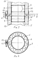
- Fig. 1 shows the ends of two ventilation pipe parts 1 and 2, each having an end face 3 and 4, between which there is a gap 15.
- the two pipes 1 and 2 are made of a mineral material that has good fire protection properties
- the material is for example vermiculite.
- the two vent pipe parts 1 and 2 are held together with an inner connector 5, which is tubular.
- the inner connector 5 has at its periphery a plurality of radially outwardly projecting and in cross-section V-shaped resilient lobes 6. These engage, as can be seen, in the intermediate space 15 and are resiliently tensioned on the end face 3 of the line part 1 at.
- the inner connector has at its ends 8 and 9 in each case at least one, preferably a plurality of circumferential sealing grooves 10, which are formed like a sipe and abut respectively on an inner side 18 and 19 of a pipe part 1 and 2 respectively.
- These sealing grooves 10 seal the inner connector 5 against the tube part 1 or 2 from gas and smoke-tight.
- the grooves 10 may be made of sheet metal, for example. As can be seen, the tightness of the quality of the end faces 3 and 4, for example, not affected by their orientation. The corresponding conduit parts 1 and 2 can thus be roughly cut.
- an outer connector 11 which has two inwardly directed peripheral edges 14, which are applied to the outside of the ventilation tube parts 1 and 2 under tension.
- the outer connector 11 is designed as a pipe clamp and has at least one clamping screw 12 and clamping jaws 13. Both the inner connector 5 and the outer connector 11 allow a length compensation, ie a displacement of the ventilation pipe parts 1 and 2 in its longitudinal direction, wherein the gap 15 is increased or decreased. The tightness and tensile strength are not affected here.
- connection is simple and requires no chemical additives.
- the ventilation pipe parts 1 and 2 are cut to length, which, as mentioned, can be done without special care.
- the inner connector 5 is inserted into the ventilation pipe parts 1 and 2, so that between the end faces 3 and 4 there is a gap 15 in which the tabs 6 resiliently engage.
- the outer connector 11 is finally applied and tensioned with the clamping screw 12.
- a solution of the connection is possible at any time without damage.
Landscapes
- Engineering & Computer Science (AREA)
- General Engineering & Computer Science (AREA)
- Mechanical Engineering (AREA)
- Chemical & Material Sciences (AREA)
- Combustion & Propulsion (AREA)
- Rigid Pipes And Flexible Pipes (AREA)
- Quick-Acting Or Multi-Walled Pipe Joints (AREA)
- Duct Arrangements (AREA)
- Joints Allowing Movement (AREA)
Description
- Die Erfindung betrifft eine Verbindung nach dem Oberbegriff des Anspruchs 1.
- Die gattungsgemässe DE 88 07 753 U offenbart einen Kompensator zum Ausgleich der Längenänderungen von Kunststoffrohren. Nach der Ausführung gemäss den Figuren 1 und 2 ist ein Dehn-Stauch-Bereich vorgesehen, der als nach aussen ragenden und umlaufenden Wulst ausgebildet ist. Der Bereich besteht aus Gummi, Kautschuk, Polytetrafluorethylen, Polyester, aus einem ein- oder beidseitig beschichteten Textil aus Metall- oder Kunststoffdraht, aus Synthetik- oder Naturgewebe, aus Nonwoven oder aus Werkstoffkombinationen. Bei brandgeschützten Verbindungen in Lüftungsrohren eignen sich Werkstoffe aus Gummi und Kunststoffen nicht. Würde der Dehn-Stauch-Bereich aus Metall hergestellt, wäre dieser vergleichsweise starr und würde keinen wesentlichen Längenausgleich zulassen.
- Die DE 32 34 277 A offenbart eine Verbindung von zwei Verbundsrohren, die einen rohrförmigen Innenverbinder aufweist, der jeweils mit einem Ende in ein Rohr eingreift. An der Aussenseite des Innenverbinders ist gemäss Figur 3 ein Gummipuffer für den Längenausgleich in Längsrichtung der beiden Verbundrohre angeordnet. Gummipuffer eignen sich für brandgeschützte Systeme nicht und können Toleranzen der Stirnflächen der verbundenen Rohre nur sehr begrenzt aufnehmen.
- Lüftungsrohre aus einem mineralischen Werkstoff und insbesondere aus Vermiculit sind aus der DE 195 42 069 bekannt. Bei brandgeschützten Systemen mit solchen Rohrteilen ist es wesentlich, dass diese dicht miteinander verbunden sind. Dazu sind die in dieser Schrift offenbarten Rohrteile so ausgebildet, dass sie zusammengesteckt werden können. Zudem wird vorgeschlagen, die Rohrteile mit stumpfem Stoss aneinandergrenzen zu lassen und durch einen Kleber miteinander zu verbinden. Das Verkleben von Lüftungsrohrteilen auf der Baustelle ist jedoch aufwendig und die mechanische Festigkeit der Verbindung und insbesondere die Zugfestigkeit ist häufig nicht ausreichend. Zudem werden an die Toleranzen und insbesondere an die Qualität der Stossflächen hohe Anforderungen gestellt, die nicht immer gewährleistet werden können.
- Der Erfindung liegt die Aufgabe zugrunde, eine Verbindung von mineralische Lüftungsrohrteilen zu schaffen, die einfacher montierbar und dennoch gas- und rauchdicht ist.
- Die Aufgabe ist gemäss Anspruch 1 gelöst. Die erfindungsgemässe Verbindung ermöglicht eine mechanische und einfache Montage ohne Hilfsstoffe, wobei zudem grosse Toleranzen zulässig sind. Die Rohrteile können grob abgelängt werden und die Stossflächen müssen nicht genau senkrecht zur Längsrichtung verlaufen. Für die Abdichtung wird die bei solchen Rohrteilen gewährleistete glatte Innenfläche verwendet. Eine besonders kostengünstige Ausführung ergibt sich dann, wenn gemäss einer Weiterbildung der Erfindung die Mittel für einen Längenausgleich durch einen brandfesten und federelastischen Werkstoff gebildet sind, die an der Aussenseite des Innenverbinders angeordnet sind. Diese Mittel sind durch lamellenartige Federelemente gebildet, die nach aussen und zwischen die Stirnseiten der beiden Lüftungsrohrteile eingreifen.
- Ein Innenverbinder mit solchen Federelementen kann sehr kostengünstig durch Stanzen eines Bleches hergestellt werden. Eine besonders hohe Zugfestigkeit und kraftschlüssige Verbindung ergibt sich dann, wenn gemäss einer Weiterbildung der Erfindung ein
- Aussenverbinder vorgesehen ist, der beispielsweise als Rohrschelle ausgebildet ist.
- Weitere vorteilhafte Merkmale ergeben sich aus den abhängigen Patentansprüchen, der nachfolgenden Beschreibung sowie der Zeichnung.
- Ein Ausführungsbeispiel der Erfindung wird nachfolgend anhand der Zeichnung näher erläutert. Es zeigen:
- Fig. 1
- ein Längsschnitt durch eine erfindungsgemässe Verbindung und
- Fig. 2
- ein Querschnitt entlang der Linie II-II der Fig. 1.
- Die Fig. 1 zeigt die Enden zweier Lüftungsrohrteile 1 und 2, die jeweils eine Stirnseite 3 bzw. 4 aufweisen, zwischen denen ein Zwischenraum 15 besteht. Die beiden Leitungsrohre 1 und 2 bestehen aus einem mineralischen Werkstoff, der gute Brandschutz-Eigenschaften besitzt Der Werkstoff ist beispielsweise Vermiculit.
- Die beiden Lüftungsrohrteile 1 und 2 werden mit einem Innenverbinder 5 zusammengehalten, der rohrförmig ausgebildet ist. Im Bereich 17 weist der Innenverbinder 5 an seinem Umfang mehrere radial nach aussen vorspringende und im Querschnitt V-förmige federelastische Lappen 6 auf. Diese greifen, wie ersichtlich, in den Zwischenraum 15 ein und liegen federelastisch gespannt an der Stirnfläche 3 des Leitungsteiles 1 an.
- Der Innenverbinder weist an seinen Enden 8 und 9 jeweils wenigstens eine, vorzugsweise mehrere umlaufende Dichtrillen 10 auf, die sickenartig ausgebildet sind und jeweils an einer Innenseite 18 bzw. 19 eines Rohrteiles 1 bzw. 2 anliegen. Diese Dichtrillen 10 dichten den Innenverbinder 5 gegenüber dem Rohrteil 1 bzw. 2 gas- und rauchdicht ab. Anstelle der Rillen 10 sind aber auch andere geeignete Dichtmittel denkbar, welche die geforderte Gas- und Rauchdichtigkeit gewährleisten. Die Rillen 10 haben jedoch den Vorteil, dass sie sehr einfach herstellbar sind und keine zusätzlichen Dichtmittel erforderlich sind. Der Innenverbinder 5 kann beispielsweise aus Blech hergestellt sein. Wie ersichtlich, ist die Dichtigkeit von der Qualität der Stirnseiten 3 und 4, beispielsweise von deren Ausrichtung nicht beeinflusst. Die entsprechenden Leitungsrohrteile 1 und 2 können damit grob abgelängt werden.
- Ist eine besonders zugfeste und kraftschlüssige Verbindung erforderlich, so ist ein Aussenverbinder 11 vorgesehen, der zwei nach innen gerichtete umlaufende Ränder 14 aufweist, die aussenseitig an den Lüftungsrohrteilen 1 und 2 unter Spannung angelegt sind. Der Aussenverbinder 11 ist als Rohrschelle ausgebildet und weist wenigstens eine Spannschraube 12 sowie Spannbacken 13 auf. Sowohl der Innenverbinder 5 als auch der Aussenverbinder 11 ermöglichen einen Längenausgleich, d.h. eine Verschiebung der Lüftungsrohrteile 1 und 2 in ihrer Längsrichtung, wobei der Zwischenraum 15 vergrössert oder verkleinert wird. Die Dichtigkeit und die Zugfestigkeit werden hierbei nicht beeinträchtigt.
- Die Montage der Verbindung ist einfach und erfordert keine chemischen Hilfsstoffe. Bei der Montage werden die Lüftungsrohrteile 1 und 2 abgelängt, was wie erwähnt, ohne besondere Sorgfalt erfolgen kann. Anschliessend wird der Innenverbinder 5 in die Lüftungsrohrteile 1 und 2 eingeschoben, sodass zwischen den Stirnseiten 3 und 4 ein Zwischenraum 15 besteht, in welchen die Lappen 6 federnd eingreifen. Gegebenenfalls wird schliesslich der Aussenverbinder 11 angelegt und mit der Spannschraube 12 gespannt. Im Gegensatz zu einer Klebeverbindung ist jederzeit ohne Beschädigung eine Lösung der Verbindung möglich.
Claims (4)
- Verbindung mit zwei Lüftungsrohrteilen (1, 2), die sich an einer Stossstelle mit stirnseitigen Flächen (3, 4) gegenüberliegen und aus einem nicht brennbaren und vorzugsweise mineralischen Werkstoff hergestellt sind, mit einem rohrförmig ausgebildeten Innenverbinder (5), der mit jeweils einem Ende in die Lüftungsrohrteile (1, 2) eingreift, wobei der Innenverbinder (5), Mittel (6, 17) für einen Längenausgleich in Längsrichtung der beiden Lüftungsrohrteile (1, 2) aufweist, dadurch gekennzeichnet, dass die Mittel (6, 17) für den Längenausgleich als federelastische Lappen (6) ausgebildet sind, die gestanzte Blechteile sind, die an der Aussenseite des Innenverbinders (5) angeordnet sind und die am Umfang des rohrförmig ausgebildeten Innenverbinders nach aussen in einen Zwischenraum (15) zwischen den stirnseitigen Flächen (3, 4) der beiden Lüftungsrohrteile (1, 2) eingreifen und federelastisch gespannt an der einen stirnseitigen Fläche (3) des einen Lüftungsrohrteiles (1) anliegen.
- Verbindung nach Anspruch 1, dadurch gekennzeichnet, dass der Innenverbinder (5) an seinem Umfang nach aussen ragende Dichtungsrillen (10) aufweist, die jeweils an einer Innenseite (18, 19) der Lüftungsrohrteile (1, 2) anliegen.
- Verbindung nach einem der Ansprüche 1 bis 3, dadurch gekennzeichnet, dass ein Aussenverbinder (11) zum kraftschlüssigen Verbinden der beiden Lüftungsrohrteile (1, 2) vorgesehen ist.
- Innenverbinder für eine Verbindung nach Anspruch 1, der rohrförmig ausgebildet ist und zwei Enden (8, 9) aufweist, die jeweils in ein Lüftungsrohrteil (1, 2) einzusetzen sind und Mittel (6, 17) für einen Längenausgleich in Längsrichtung der beiden Lüftungsrohrteile (1, 2) aufweist, dadurch gekennzeichnet, dass die Mittel (6, 17) für den Längenausgleich als federelastische Lappen (6) ausgebildet sind, die gestanzte Blechteile sind, die an der Aussenseite des Innenverbinders (5) angeordnet sind und die nach aussen ragen und dass er an seinem Umfang nach aussen ragende Dichtungsrillen (10) aufweist, die jeweils an einer Innenseite (18, 19) der Lüftungsrohrteile (1, 2) anzulegen sind.
Applications Claiming Priority (2)
| Application Number | Priority Date | Filing Date | Title |
|---|---|---|---|
| CH20011497 | 2001-08-14 | ||
| CH14972001 | 2001-08-14 |
Publications (3)
| Publication Number | Publication Date |
|---|---|
| EP1284386A2 EP1284386A2 (de) | 2003-02-19 |
| EP1284386A3 EP1284386A3 (de) | 2003-11-19 |
| EP1284386B1 true EP1284386B1 (de) | 2006-08-30 |
Family
ID=4565521
Family Applications (1)
| Application Number | Title | Priority Date | Filing Date |
|---|---|---|---|
| EP02405682A Expired - Lifetime EP1284386B1 (de) | 2001-08-14 | 2002-08-08 | Verbindung zwischen zwei Lüftungsrohrteilen |
Country Status (3)
| Country | Link |
|---|---|
| EP (1) | EP1284386B1 (de) |
| AT (1) | ATE338237T1 (de) |
| DE (1) | DE50207979D1 (de) |
Family Cites Families (7)
| Publication number | Priority date | Publication date | Assignee | Title |
|---|---|---|---|---|
| US2232936A (en) * | 1940-05-02 | 1941-02-25 | Allis Chaimers Mfg Company | Expansion joint |
| US3269754A (en) * | 1964-03-02 | 1966-08-30 | Mc Graw Edison Co | Internal plastic coupling |
| DE3234277A1 (de) * | 1982-09-13 | 1984-03-15 | Ametex AG, 8867 Niederurnen | Loesbare rohrkupplung, insbesondere fuer verbundrohre |
| DE3518428A1 (de) * | 1985-05-22 | 1986-11-27 | DSD Dillinger Stahlbau GmbH, 6670 St Ingbert | Verbindung fuer rohre der lueftungstechnik |
| DE8807753U1 (de) * | 1988-06-15 | 1988-08-18 | E & S Planbau Stahl und Rohrleitungsbau Montagen GmbH, 4350 Recklinghausen | Kompensator zum Ausgleich der Längenänderungen von Kunststoffrohren, insbesondere von GFK-Rohren |
| JPH0786395B2 (ja) * | 1993-06-04 | 1995-09-20 | 保雄 梶原 | ダクト接続装置 |
| DE9418205U1 (de) | 1994-11-12 | 1996-03-14 | Pafamax Brandschutztechnik GmbH, 34123 Kassel | Bauelement aus einem nicht brennbaren Material |
-
2002
- 2002-08-08 AT AT02405682T patent/ATE338237T1/de not_active IP Right Cessation
- 2002-08-08 EP EP02405682A patent/EP1284386B1/de not_active Expired - Lifetime
- 2002-08-08 DE DE50207979T patent/DE50207979D1/de not_active Expired - Lifetime
Also Published As
| Publication number | Publication date |
|---|---|
| EP1284386A3 (de) | 2003-11-19 |
| EP1284386A2 (de) | 2003-02-19 |
| ATE338237T1 (de) | 2006-09-15 |
| DE50207979D1 (de) | 2006-10-12 |
Similar Documents
| Publication | Publication Date | Title |
|---|---|---|
| DE2335119C3 (de) | Rohrkupplung | |
| EP0521324B2 (de) | Kabelmuffe | |
| DE2724793A1 (de) | Dichtungsvorrichtung | |
| DE202017102758U1 (de) | Abluftkanalanordnung für ein Küchenabluftkanalsystem | |
| EP1662630A2 (de) | Verbindungsmuffe | |
| DE2911575A1 (de) | Zugfeste rohrkupplung | |
| EP1026376A2 (de) | Abkoppelelement zur Abkopplung von Schwingungen | |
| EP1079064B1 (de) | Druckausgleichsring für eine Verbindung zwischen Vortriebrohren | |
| DE19536703A1 (de) | Rohr, insbesondere Kunststoffrohr, und Rohrverbindung aus solchen Rohren | |
| DE9215544U1 (de) | Steckmuffenverbindung | |
| WO2024120949A1 (de) | Steckverbinder | |
| EP0789823B1 (de) | Lösbare verbindungs- oder dichtvorrichtung zur übertragung axialer zugkräfte oder fluiddruckkräfte | |
| DE102007014003A1 (de) | Rohrverbindungsvorrichtung | |
| EP1284386A2 (de) | Verbindung zwischen zwei Lüftungsrohrteilen | |
| DE102012012177B4 (de) | Elastisches Lager | |
| EP1265020B1 (de) | Flexible Gasleitung | |
| DE2141846A1 (de) | Rohrkupplung | |
| DE69713018T2 (de) | Entkupplungsvorrichtung, die zwischen zwei Rohrleitungsabschnitte eingesetzt werden kann | |
| EP2489898A2 (de) | Lager sowie Verfahren zu dessen Herstellung | |
| DE202017104269U1 (de) | Dunstabzugssystem | |
| DE2131686B2 (de) | Kabelmuffe | |
| DE1475874A1 (de) | Rohrkupplung | |
| DE19548719C1 (de) | Flexible Steckverbindung für Abgasleitungen | |
| EP0689010A2 (de) | Dichtungsanordnung in einer Rauchgasarmatur | |
| EP0916888A1 (de) | Rohrkupplung |
Legal Events
| Date | Code | Title | Description |
|---|---|---|---|
| PUAI | Public reference made under article 153(3) epc to a published international application that has entered the european phase |
Free format text: ORIGINAL CODE: 0009012 |
|
| AK | Designated contracting states |
Designated state(s): AT BE BG CH CY CZ DE DK EE ES FI FR GB GR IE IT LI LU MC NL PT SE SK TR |
|
| AX | Request for extension of the european patent |
Extension state: AL LT LV MK RO SI |
|
| PUAL | Search report despatched |
Free format text: ORIGINAL CODE: 0009013 |
|
| AK | Designated contracting states |
Kind code of ref document: A3 Designated state(s): AT BE BG CH CY CZ DE DK EE ES FI FR GB GR IE IT LI LU MC NL PT SE SK TR |
|
| AX | Request for extension of the european patent |
Extension state: AL LT LV MK RO SI |
|
| 17P | Request for examination filed |
Effective date: 20031218 |
|
| 17Q | First examination report despatched |
Effective date: 20040401 |
|
| AKX | Designation fees paid |
Designated state(s): AT BE BG CH CY CZ DE DK EE ES FI FR GB GR IE IT LI LU MC NL PT SE SK TR |
|
| GRAP | Despatch of communication of intention to grant a patent |
Free format text: ORIGINAL CODE: EPIDOSNIGR1 |
|
| GRAS | Grant fee paid |
Free format text: ORIGINAL CODE: EPIDOSNIGR3 |
|
| GRAA | (expected) grant |
Free format text: ORIGINAL CODE: 0009210 |
|
| AK | Designated contracting states |
Kind code of ref document: B1 Designated state(s): AT BE BG CH CY CZ DE DK EE ES FI FR GB GR IE IT LI LU MC NL PT SE SK TR |
|
| PG25 | Lapsed in a contracting state [announced via postgrant information from national office to epo] |
Ref country code: IT Free format text: LAPSE BECAUSE OF FAILURE TO SUBMIT A TRANSLATION OF THE DESCRIPTION OR TO PAY THE FEE WITHIN THE PRE;WARNING: LAPSES OF ITALIAN PATENTS WITH EFFECTIVE DATE BEFORE 2007 MAY HAVE OCCURRED AT ANY TIME BEFORE 2007. THE CORRECT EFFECTIVE DATE MAY BE DIFFERENT FROM THE ONE RECORDED.SCRIBED TIME-LIMIT Effective date: 20060830 Ref country code: GB Free format text: LAPSE BECAUSE OF FAILURE TO SUBMIT A TRANSLATION OF THE DESCRIPTION OR TO PAY THE FEE WITHIN THE PRESCRIBED TIME-LIMIT Effective date: 20060830 Ref country code: CZ Free format text: LAPSE BECAUSE OF FAILURE TO SUBMIT A TRANSLATION OF THE DESCRIPTION OR TO PAY THE FEE WITHIN THE PRESCRIBED TIME-LIMIT Effective date: 20060830 Ref country code: SK Free format text: LAPSE BECAUSE OF FAILURE TO SUBMIT A TRANSLATION OF THE DESCRIPTION OR TO PAY THE FEE WITHIN THE PRESCRIBED TIME-LIMIT Effective date: 20060830 Ref country code: NL Free format text: LAPSE BECAUSE OF FAILURE TO SUBMIT A TRANSLATION OF THE DESCRIPTION OR TO PAY THE FEE WITHIN THE PRESCRIBED TIME-LIMIT Effective date: 20060830 Ref country code: FI Free format text: LAPSE BECAUSE OF FAILURE TO SUBMIT A TRANSLATION OF THE DESCRIPTION OR TO PAY THE FEE WITHIN THE PRESCRIBED TIME-LIMIT Effective date: 20060830 Ref country code: IE Free format text: LAPSE BECAUSE OF FAILURE TO SUBMIT A TRANSLATION OF THE DESCRIPTION OR TO PAY THE FEE WITHIN THE PRESCRIBED TIME-LIMIT Effective date: 20060830 |
|
| REG | Reference to a national code |
Ref country code: GB Ref legal event code: FG4D Free format text: NOT ENGLISH |
|
| REG | Reference to a national code |
Ref country code: CH Ref legal event code: EP |
|
| REG | Reference to a national code |
Ref country code: IE Ref legal event code: FG4D Free format text: LANGUAGE OF EP DOCUMENT: GERMAN |
|
| REF | Corresponds to: |
Ref document number: 50207979 Country of ref document: DE Date of ref document: 20061012 Kind code of ref document: P |
|
| PG25 | Lapsed in a contracting state [announced via postgrant information from national office to epo] |
Ref country code: DK Free format text: LAPSE BECAUSE OF FAILURE TO SUBMIT A TRANSLATION OF THE DESCRIPTION OR TO PAY THE FEE WITHIN THE PRESCRIBED TIME-LIMIT Effective date: 20061130 Ref country code: SE Free format text: LAPSE BECAUSE OF FAILURE TO SUBMIT A TRANSLATION OF THE DESCRIPTION OR TO PAY THE FEE WITHIN THE PRESCRIBED TIME-LIMIT Effective date: 20061130 Ref country code: BG Free format text: LAPSE BECAUSE OF FAILURE TO SUBMIT A TRANSLATION OF THE DESCRIPTION OR TO PAY THE FEE WITHIN THE PRESCRIBED TIME-LIMIT Effective date: 20061130 |
|
| PG25 | Lapsed in a contracting state [announced via postgrant information from national office to epo] |
Ref country code: ES Free format text: LAPSE BECAUSE OF FAILURE TO SUBMIT A TRANSLATION OF THE DESCRIPTION OR TO PAY THE FEE WITHIN THE PRESCRIBED TIME-LIMIT Effective date: 20061211 |
|
| NLV1 | Nl: lapsed or annulled due to failure to fulfill the requirements of art. 29p and 29m of the patents act | ||
| GBV | Gb: ep patent (uk) treated as always having been void in accordance with gb section 77(7)/1977 [no translation filed] |
Effective date: 20060830 |
|
| REG | Reference to a national code |
Ref country code: IE Ref legal event code: FD4D |
|
| EN | Fr: translation not filed | ||
| PLBE | No opposition filed within time limit |
Free format text: ORIGINAL CODE: 0009261 |
|
| STAA | Information on the status of an ep patent application or granted ep patent |
Free format text: STATUS: NO OPPOSITION FILED WITHIN TIME LIMIT |
|
| 26N | No opposition filed |
Effective date: 20070531 |
|
| BERE | Be: lapsed |
Owner name: GEBERIT TECHNIK A.G. Effective date: 20070831 |
|
| REG | Reference to a national code |
Ref country code: CH Ref legal event code: PL |
|
| PG25 | Lapsed in a contracting state [announced via postgrant information from national office to epo] |
Ref country code: MC Free format text: LAPSE BECAUSE OF NON-PAYMENT OF DUE FEES Effective date: 20070831 Ref country code: FR Free format text: LAPSE BECAUSE OF FAILURE TO SUBMIT A TRANSLATION OF THE DESCRIPTION OR TO PAY THE FEE WITHIN THE PRESCRIBED TIME-LIMIT Effective date: 20070511 Ref country code: GR Free format text: LAPSE BECAUSE OF FAILURE TO SUBMIT A TRANSLATION OF THE DESCRIPTION OR TO PAY THE FEE WITHIN THE PRESCRIBED TIME-LIMIT Effective date: 20061201 Ref country code: LI Free format text: LAPSE BECAUSE OF NON-PAYMENT OF DUE FEES Effective date: 20070831 Ref country code: CH Free format text: LAPSE BECAUSE OF NON-PAYMENT OF DUE FEES Effective date: 20070831 |
|
| PG25 | Lapsed in a contracting state [announced via postgrant information from national office to epo] |
Ref country code: EE Free format text: LAPSE BECAUSE OF FAILURE TO SUBMIT A TRANSLATION OF THE DESCRIPTION OR TO PAY THE FEE WITHIN THE PRESCRIBED TIME-LIMIT Effective date: 20060830 |
|
| PG25 | Lapsed in a contracting state [announced via postgrant information from national office to epo] |
Ref country code: BE Free format text: LAPSE BECAUSE OF NON-PAYMENT OF DUE FEES Effective date: 20070831 |
|
| PG25 | Lapsed in a contracting state [announced via postgrant information from national office to epo] |
Ref country code: FR Free format text: LAPSE BECAUSE OF FAILURE TO SUBMIT A TRANSLATION OF THE DESCRIPTION OR TO PAY THE FEE WITHIN THE PRESCRIBED TIME-LIMIT Effective date: 20060830 Ref country code: AT Free format text: LAPSE BECAUSE OF NON-PAYMENT OF DUE FEES Effective date: 20070808 |
|
| PG25 | Lapsed in a contracting state [announced via postgrant information from national office to epo] |
Ref country code: LU Free format text: LAPSE BECAUSE OF NON-PAYMENT OF DUE FEES Effective date: 20070808 Ref country code: CY Free format text: LAPSE BECAUSE OF FAILURE TO SUBMIT A TRANSLATION OF THE DESCRIPTION OR TO PAY THE FEE WITHIN THE PRESCRIBED TIME-LIMIT Effective date: 20060830 |
|
| PG25 | Lapsed in a contracting state [announced via postgrant information from national office to epo] |
Ref country code: TR Free format text: LAPSE BECAUSE OF FAILURE TO SUBMIT A TRANSLATION OF THE DESCRIPTION OR TO PAY THE FEE WITHIN THE PRESCRIBED TIME-LIMIT Effective date: 20060830 |
|
| PGFP | Annual fee paid to national office [announced via postgrant information from national office to epo] |
Ref country code: DE Payment date: 20090821 Year of fee payment: 8 |
|
| REG | Reference to a national code |
Ref country code: DE Ref legal event code: R119 Ref document number: 50207979 Country of ref document: DE Effective date: 20110301 |
|
| PG25 | Lapsed in a contracting state [announced via postgrant information from national office to epo] |
Ref country code: DE Free format text: LAPSE BECAUSE OF NON-PAYMENT OF DUE FEES Effective date: 20110301 |
|
| PG25 | Lapsed in a contracting state [announced via postgrant information from national office to epo] |
Ref country code: PT Free format text: LAPSE BECAUSE OF FAILURE TO SUBMIT A TRANSLATION OF THE DESCRIPTION OR TO PAY THE FEE WITHIN THE PRESCRIBED TIME-LIMIT Effective date: 20060830 |