EP1283966B1 - Armatur, insbesondere kükenhahn - Google Patents
Armatur, insbesondere kükenhahn Download PDFInfo
- Publication number
- EP1283966B1 EP1283966B1 EP01940508A EP01940508A EP1283966B1 EP 1283966 B1 EP1283966 B1 EP 1283966B1 EP 01940508 A EP01940508 A EP 01940508A EP 01940508 A EP01940508 A EP 01940508A EP 1283966 B1 EP1283966 B1 EP 1283966B1
- Authority
- EP
- European Patent Office
- Prior art keywords
- housing
- opening
- rotatable body
- ring
- fitting
- Prior art date
- Legal status (The legal status is an assumption and is not a legal conclusion. Google has not performed a legal analysis and makes no representation as to the accuracy of the status listed.)
- Expired - Lifetime
Links
- 238000007789 sealing Methods 0.000 claims description 29
- 239000012528 membrane Substances 0.000 claims description 7
- 239000012530 fluid Substances 0.000 abstract description 5
- 229920001343 polytetrafluoroethylene Polymers 0.000 description 5
- 239000004810 polytetrafluoroethylene Substances 0.000 description 5
- 239000004033 plastic Substances 0.000 description 4
- 238000010276 construction Methods 0.000 description 3
- 238000009434 installation Methods 0.000 description 3
- 241000287828 Gallus gallus Species 0.000 description 2
- 235000013330 chicken meat Nutrition 0.000 description 2
- 229910000831 Steel Inorganic materials 0.000 description 1
- 230000002411 adverse Effects 0.000 description 1
- 230000006835 compression Effects 0.000 description 1
- 238000007906 compression Methods 0.000 description 1
- 230000007812 deficiency Effects 0.000 description 1
- 230000001419 dependent effect Effects 0.000 description 1
- 238000011161 development Methods 0.000 description 1
- 230000018109 developmental process Effects 0.000 description 1
- 238000004519 manufacturing process Methods 0.000 description 1
- -1 polytetrafluoroethylene Polymers 0.000 description 1
- 239000002689 soil Substances 0.000 description 1
- 239000010959 steel Substances 0.000 description 1
- 230000007704 transition Effects 0.000 description 1
- 238000003466 welding Methods 0.000 description 1
Images


Classifications
-
- F—MECHANICAL ENGINEERING; LIGHTING; HEATING; WEAPONS; BLASTING
- F16—ENGINEERING ELEMENTS AND UNITS; GENERAL MEASURES FOR PRODUCING AND MAINTAINING EFFECTIVE FUNCTIONING OF MACHINES OR INSTALLATIONS; THERMAL INSULATION IN GENERAL
- F16K—VALVES; TAPS; COCKS; ACTUATING-FLOATS; DEVICES FOR VENTING OR AERATING
- F16K27/00—Construction of housing; Use of materials therefor
- F16K27/07—Construction of housing; Use of materials therefor of cutting-off parts of tanks, e.g. tank-cars
-
- Y—GENERAL TAGGING OF NEW TECHNOLOGICAL DEVELOPMENTS; GENERAL TAGGING OF CROSS-SECTIONAL TECHNOLOGIES SPANNING OVER SEVERAL SECTIONS OF THE IPC; TECHNICAL SUBJECTS COVERED BY FORMER USPC CROSS-REFERENCE ART COLLECTIONS [XRACs] AND DIGESTS
- Y10—TECHNICAL SUBJECTS COVERED BY FORMER USPC
- Y10T—TECHNICAL SUBJECTS COVERED BY FORMER US CLASSIFICATION
- Y10T137/00—Fluid handling
- Y10T137/8593—Systems
- Y10T137/86493—Multi-way valve unit
- Y10T137/86718—Dividing into parallel flow paths with recombining
- Y10T137/86743—Rotary
- Y10T137/86751—Plug
-
- Y—GENERAL TAGGING OF NEW TECHNOLOGICAL DEVELOPMENTS; GENERAL TAGGING OF CROSS-SECTIONAL TECHNOLOGIES SPANNING OVER SEVERAL SECTIONS OF THE IPC; TECHNICAL SUBJECTS COVERED BY FORMER USPC CROSS-REFERENCE ART COLLECTIONS [XRACs] AND DIGESTS
- Y10—TECHNICAL SUBJECTS COVERED BY FORMER USPC
- Y10T—TECHNICAL SUBJECTS COVERED BY FORMER US CLASSIFICATION
- Y10T137/00—Fluid handling
- Y10T137/8593—Systems
- Y10T137/86493—Multi-way valve unit
- Y10T137/86863—Rotary valve unit
- Y10T137/86871—Plug
Definitions
- the invention relates to a fitting for containers such as tankers or containers according to the features indicated in the preamble of patent claim 1.
- the sleeves mentioned in the housing via threaded connections are rotatable stored, wherein to increase the sealing force, the said sleeves independently from both sides with respect to the rotating body in opposite directions are moving. After fitting the valve into the tank, the setting is in Interior of the container feasible, or the fitting must be removed from the container get extended.
- a fitting is known whose rotary body is in the form of a chick is formed and rotatable about a substantially horizontal axis of rotation and in the Housing by means of a plastic sleeve, in particular polytetrafluoroethylene (PTFE), stored, wherein by means of the sleeve further specified the seal with respect to the housing is.
- the fitting is designed as a plug tap
- the housing has a substantially vertically arranged passage with a Inlet opening and an outlet opening has.
- the chick has a through hole with an inflow opening and an outflow opening, which in the open position with the inlet opening and the outlet opening of the housing are aligned.
- Cross section of the through hole of the plug and the outlet opening of the housing are smaller than the cross-section of a connecting piece for a pipe or a Hose for loading or filling.
- cross-section reduction have relatively long times for loading and unloading or for filling or emptying of the tank container can be accepted. It should be noted at this point that when unloading or emptying the fluid or medium stored in the container through the Inlet opening of the housing and the inflow opening of the rotary body flows and through the discharge opening of the rotary body and the outlet opening of the housing flows.
- the chick contains a small lateral Opening, which in the open position in the area of the inner bottom surface of Container to allow its complete emptying. The flow rate is not affected by this small opening.
- the rotary body as a ball with a correspondingly enlarged Cross section of the through hole formed.
- the invention is based on the object, the valve of said To further develop and optimize this type with a low design effort that with a small volume and / or a low height the Adjustment of the sealing force of the seat rings can be carried out in a simple manner, wherein further a small operating torque for rotating the rotary body should be required.
- the fitting according to the invention which is designed as a plug tap, is characterized by a simple and nevertheless functionally reliable construction and ensures in the open position of the rotary body a large passage of the medium and thus short loading times and / or unloading times.
- the cross sections of the mentioned Openings of the housing and the rotary body are predetermined and on the Cross-section of the connecting flange matched to that during loading and unloading unimpeded free flow of the medium or fluid without adverse cross-sectional reduction he follows.
- the rotary body includes a second inlet opening with a comparatively large cross-section through which a substantial portion of the through Rotary body flowing medium flows through in the open position of the rotating body.
- the cross section of the second inflow opening is essentially at least the same size as the cross section of the first inflow opening. Furthermore, in a preferred manner the cross section with the outlet opening of the housing at least approximately the same as large as the cross section of the opening of the connection flange. Furthermore, the housing contains a at least in the open position of the rotary body to said second inflow opening a substantially coaxial bearing ring or seal. In a special Design contains the housing in the region of the outflow opening of the Rotary body outlet side or to the outside of the container towards a seat ring and / or a sealing ring, due to which a low operating torque or a low Torque for rotating the rotating body is guaranteed when opening or closing.
- the housing is rotatably and sealingly mounted.
- the two inflow openings of the rotary body diametrically and preferably coaxially to each other arranged, as well as the two associated inlet openings of the housing, wherein the respective cross sections of the openings are substantially the same size.
- the axes of said openings are substantially orthogonal to the axis of rotation of the preferably formed as a chick rotating body, wherein the two inflow openings the rotary body is assigned in each case a seat ring arranged in the housing.
- the valve is integrated into a manhole cover and can in a simple Way to be connected to the container, in particular by welding.
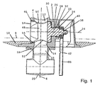
- Fig. 1 shows a section through the fitting with a housing 2 and a rotary body 4, in a sectional plane through the longitudinal axis 6.
- the valve is in the range an opening in the bottom, which is indicated by dash-dotted line 8, a Container or tanks arranged and with this suitably tight and firm connected.
- a weld-in lid 10 is provided, with which the housing appropriately connected via a flange is.
- the housing 2 below, to Outside, an outlet opening 14, to which a passage 16 of a connector body a connection flange or connecting piece, connects.
- a tee 20 is also connected.
- the cross section of the outlet opening 14 is at least approximately the same size as the cross section of the passage 16, without a cross-sectional reduction is present.
- the rotary body 4 designed as a chick is one which is preferably vertical arranged longitudinal axis 6 at least approximately orthogonal axis of rotation 24th rotatably mounted. As can be seen, penetrates a shaft 26 of the rotary body 4 a Bore 28 of the housing, wherein connected via the one piece with the rotary body Shank 26, a bearing of the rotary body 4 is predetermined. In the transition area of Rotary body 4 to the shaft 26 is a delta ring 30 is provided which partially in the said hole 28 protrudes. By means of stuffing box rings 32, 33, the seal is made to the outside, wherein an axial pressurization via a pressure ring 34th is provided.
- a lever 36 is rotatably connected to the shaft 26 for actuation, wherein means of adjusting means 38, in the form of an adjusting nut, and a disc 40th via the lever and the pressure ring 34, the stuffing box rings 32, 33 adjusted or readjusted can be.
- the lever 36 also has a predetermined breaking point 42, which is provided as close as possible to the weld-in cover 10 or the tank bottom 8.
- the connection of the connection body 18, in particular by means not shown here Screws, with the housing 2 is advantageously designed as a predetermined breaking point, so that in case of accident the valve is not damaged and fully functional and stays tight.
- the conical outer surface having chick 4 is in a conical also Bore 44 of the housing 2 is arranged, and mounted by means of a bearing ring 46.
- a Usually provided with chickens rifle for storage and sealing is not available. Rather, between the conical outer surface of the plug 4 and the Inner surface of the conical bore 44 a game or a predetermined small annular gap exist, and consequently are for the operation or rotation of the plug 4 so far no friction forces or torques to overcome.
- the storage of the chick 4 takes place on the one hand by means of the bearing ring 46 and on the other hand by means of the storage of the one-piece connected shank 26 in the region of the bore 28 of the housing 2. In comparison with known plug valves thus ensures a low operating torque.
- the rotary body 4 includes a through hole 48 having a first inflow opening 50 and diametrically thereto an outflow 52. Further, the rotary body 4 includes a second inflow opening 54, which opens into the through hole 48 and which at least approximately coaxial with the axis of rotation 24 is arranged. As can be seen, is in the region of the second inflow opening 54 radially outward in the housing 2 of the likewise to Rotary axis 24 is arranged substantially coaxial bearing ring 46.
- the second inflow opening 54 forms a direct connection between the interior of the container and the Through hole 48 of the rotary body 4. When unloading or emptying the container Thus, the medium flows not only through the first inflow opening 50, but at the same time also through the second inflow opening 54 in the through hole 48 of the 4.
- the cross section of the second inflow opening 54 is large and is at least approximately of the same order of magnitude as the cross section of first inflow opening 50. Due to the large cross-sectional area of the inflow opening 54 flows through this thus a substantial proportion of the medium. The flow resistance for the rotating body 4 and the total of the fitting flowing medium thus reduced to a minimum.
- a preferably soft sealing seat ring or sealing ring 56 is provided, which at the conical outer surface of the plug 4 sealingly rests, and made of plastic, in particular PTFE exists.
- the soft-sealing seat ring 56 is in the region of the conical inner surface 28 of the housing 2 and arranged correspondingly conical or spherically deformed.
- the through-hole 48 and the outflow opening 50 of the rotary body 4 coaxial with the longitudinal axis 6 and the outlet opening 14th lie, while in the closed position, the through-hole 48 and the outflow opening 50 assume a position rotated about 90 ° with respect to the axis of rotation 24 and the seat ring 54 at the associated, completely closed part of the outer surface of the Rotary body 4 sealingly applied.
- the conical bore 44 of the housing 2 opens from in accordance with the drawing right part of the housing 2 and the bore 28 in the direction of Longitudinal axis 6 and the opposite bearing ring 46 and there opens into the Interior of the container.
- the rotary body 4 a from the area of the shaft 26 to the free end of the rotary body 4 opening conical outer surface on.
- the adjusting means designed in particular as adjusting nut 38 the rotary body according to the drawing with respect to the housing 2 to the right or drawn into the bore 44, wherein the contact pressure and ultimately the sealing force the seat ring 56 is set and adjusted in the required manner.
- the Adjustment means or the Nachstelimutter 38 accessible from the outside of the container forth is, can the adjustment and / or adjustment of the sealing force of the seat ring 56th easily in the mounted and firmly connected to the container state of the valve be performed.
- the above setting is also the setting and specification of the sealing force of the stuffing box rings 32, 33 with respect to the shaft 26th
- Fig. 2 shows a perspective view of the fitting obliquely from below with the T-piece 20 and the operating lever 36.
- the connecting flange 18 connected by screws 58 to the lower flange of the housing 2.
- the lower Housing flange is also by means of screws 59 with the weld-in 10th connected.
- Fig. 3 shows a side view of the fitting in the viewing direction III of FIG. 2, wherein the Revolving body 4 is shown in the passage position and thus the through hole 48 coaxial with the longitudinal axis 6 extends. Also, the large second inflow opening 54 is here clearly visible.
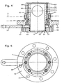
- Fig. 4 shows a particular embodiment of turn designed as a plug cock Armature whose rotary body or chicks 4 is rotatable about the longitudinal axis 6, which thus at the same time forms the axis of rotation.
- the housing 8 protruding housing 2 includes a means of screws 60 connected Lower part 62 with a flange for connection to the bottom 8 and also above one Cover 64.
- the lever To operate or to rotate the rotary body 4 is the lever with this 36 rotatably connected, which indicated with dash-dotted line breaking point 42 has.
- the housing 2 contains inside the conical bore 44, the cone angle opens downwards or in the direction of the lower part 62 and / or the lever 36.
- connection body 18 is on the underside arranged, which is preferably designed as a pipe flange and in more convenient Shoes threaded holes 68 for connection to a trained Flange contains a pipeline or the like.
- the rotary body 4 protrudes into the Area of the connection body 18 and by means of at least one, expediently two Sealing rings 70, which are designed in particular as delta rings, takes place Sealing to the outside.
- the rotary body 4 includes the first inflow opening 50 and diametrically to this, the second inflow opening is provided in front of the plane of the drawing.
- the two inlet openings open into the inner passage 48 of the rotating body 4, wherein the passage 48 is preferably formed as a through hole and below has the discharge opening 52, the cross-sectional area or radius substantially is the same size as in the outlet opening 14 in the connection body 18 of the housing second
- Fig. 5 shows a plan view of the fitting with the housing 2, which by means of screws 60 is connected to the lower part 62.
- the lower part 62 is a housing flange formed and includes through holes 72 for connection to the bottom of the Container.
- Fig. 6 shows a section through the valve of FIG. 4 in a 90 ° relative to the Longitudinal axis 6 rotated position.
- the two Inlet openings 50, 54 are diametrically disposed and coaxial with respect to a common axis 74, which is substantially orthogonal to the longitudinal axis 6.
- the two inlet openings 50, 54 are expedient part of a through hole through the rotary body 4 transversely to its rotational and longitudinal axis 6.
- the two Inlet openings 50, 54 suitably have equal radii 76 and the Outflow opening 52 has a radius 78.
- the radii 76 on the one hand and the radius 78th On the other hand, are predetermined such that the sum of the cross-sectional areas of the two Inlet openings 50, 54 at least approximately the same size as the cross-sectional area the outflow opening 52 and / or the passage 48, which in particular as Through hole is formed.
- the radii 76 of the transverse inflow openings 50, 54 are thus given comparatively small, the height, in the direction the longitudinal axis 6 of the valve, correspondingly set low.
- a free space 79 for receiving the lever 36 is provided between the lower part 62 and the connector body 18 .
- Position is for sealing between the rotary body 4 and the housing 2 in Area of said conical annular gap in each case a preferably soft-sealing Seat ring 80, 82 arranged.
- the two seat rings 80, 82 are corresponding to the conical Outer surface of the rotary body 4 conically and / or spherically curved in the region of Inner surface of the housing 2 is arranged.
- the seat rings 80, 82 are each part preferably cylindrical bushes 84 which in the axis of rotation 6 transverse and diametrically arranged inlet openings 12 are inserted.
- the Seat rings 80, 82 By integrating the Seat rings 80, 82 in the respective socket 84 and their definition in the diametrical Inlet openings 12 ensures a secure fixation in the housing 2. Production and the installation of the seat rings 80, 82 integrated into the two bushes 84 is thus in easy to carry out. It is of particular importance that the radii of the Inlet openings 12 and / or the inner surfaces of the sockets 84 at least approximately are the same size as the radii 76 of the associated inlet openings 50, 54th Da thus, the corresponding cross-sectional areas are substantially the same, is none Cross-section reduction and / or an increase in the flow resistance given.
- the seat rings 80, 82 together with associated bushes 84 are again made of plastic, especially PTFE.
- a pressure ring 86th provided in the housing or its lower part or housing flange 62 , which is fixed by means of screws 88.
- the pressure ring 86 is coaxial with Arranged axis 6 and is preferably used for storage of the rotary body. 4
- Fig. 7 shows enlarged detail X according to FIG. 6, wherein the rotary body 4 and the Pressure ring 86, the housing and the lower part 62 are partially shown.
- the membrane 90 is formed soft-sealing and made of plastic, in particular PTFE, while the membrane 91 is formed as a steel membrane.
- the membranes 90, 91 are annular and lie with a radially inner edge on one Ring shoulder of the rotary body.
- a sealing ring 94 On the other side of the mentioned edge of the Diaphragm 90 is a sealing ring 94, which is preferably designed as a delta ring and further sealingly abuts the outer surface of the rotary body 4.
- Axial between the Pressure ring 86 and the diaphragm 90 is also a preferred annular pressure body 96th arranged. Further, between the rotary body 4 and the housing 2, a sealing ring 98th arranged, which is preferably formed as a U-ring.
- FIG. 6 is It can be seen that by means of the screws 88 of the pressure ring 86 axially adjustable and consequently via the pressure body 96 and the diaphragm 90, the axial adjustment of the rotary body. 4 and finally the compression and / or sealing force of the seat rings 80, 82 can be predetermined.
- the explained setting can also be easily installed in the container Armature made from the outside.
- FIG. 8 shows a perspective view of the fitting according to FIGS. 4 to 7 with the housing 2 and the one bushing 84.
- the housing 2 By means of the screws 60 is the housing 2 connected to the lower part or threaded flange 62, which the through holes 72 for attachment to the outside of the bottom of the container.
Landscapes
- Engineering & Computer Science (AREA)
- General Engineering & Computer Science (AREA)
- Mechanical Engineering (AREA)
- Taps Or Cocks (AREA)
- Dowels (AREA)
- Joints Allowing Movement (AREA)
- Quick-Acting Or Multi-Walled Pipe Joints (AREA)
- Mechanically-Actuated Valves (AREA)
- Multiple-Way Valves (AREA)
- Ultra Sonic Daignosis Equipment (AREA)
- Ceramic Products (AREA)
- Discharge Heating (AREA)
Description
- Fig. 1
- einen Schnitt durch ein erstes Ausführungsbeispiel, wobei der Drehkörper in der offenen Position bzw. bei freigegebenem Durchlass dargestellt ist,
- Fig. 2,3
- Ansichten der Armatur gemäß Fig. 1,
- Fig. 4
- einen Schnitt durch ein weiteres Ausführungsbeispiel,
- Fig. 5
- eine Ansicht der Armatur gemäß Fig. 4,
- Fig. 6
- einen Schnitt durch die Armatur entlang Schnittebene A gemäß Fig. 4,
- Fig. 7
- eine vergrößerte Detaildarstellung X gemäß Fig. 6,
- Fig. 8
- eine perspektivische Darstellung der Armatur gemäß Fig. 4 bis 7.
- 2
- Gehäuse
- 4
- Drehkörper / Küken
- 6
- Längsachse
- 8
- Boden / Behälter
- 10
- Einschweißdeckel
- 12
- Einlassöffnung von 2
- 14
- Austassöffnung von 2
- 16
- Durchgang von 18
- 18
- Anschlusskörper
- 20
- T-Stück
- 24
- Drehachse
- 26
- Schaft von 4
- 28
- Bohrung in 2
- 30
- Deltaring
- 32, 33
- Stopfbuchsring
- 34
- Druckring
- 36
- Hebel
- 38
- Einstellmittel / Einstellmutter
- 40
- Scheibe
- 42
- Sollbruchstelle in 36
- 44
- konische Bohrung in 2
- 46
- Lagerring
- 48
- Durchgangsbohrung in 4
- 50
- erste Einströmöffnung
- 52
- Ausströmöffnung von 4
- 54
- zweite Einströmöffnung von 4
- 56
- Sitzring
- 58-60
- Schraube
- 62
- Unterteil von 2
- 64
- Deckel von 2
- 66
- konischer Ringspalt
- 68
- Gewindebohrung in 18
- 70
- Dichtungsring / Deltaring
- 72
- Durchgangsbohrung in 62
- 74
- Achse von 50, 54
- 76
- Radius von 50, 54
- 78
- Radius von 52
- 79
- Freiraum
- 80,82
- Sitzring
- 84
- Buchse
- 86
- Druckring
- 88
- Schraube
- 90
- Membrane
- 92
- Ringschulter von 4
- 94
- Dichtring
- 96
- Druckkörper
- 98
- Dichtring / O-Ring
Claims (9)
- Armatur für Behälter wie Tankwagen oder Container, enthaltend ein Gehäuse (2), weiches zwei Einlassöffnungen (12) und eine Auslassöffnung (14) aufweist, sowie einen Drehkörper (4) mit einem Durchgang (48), welcher zwei Einströmöffnungen (50, 54) und eine Ausströmöffnung (52) aufweist, wobei der Drehkörper (4) im Gehäuse (2) drehbar angeordnet ist, um die Verbindung zwischen den Einlassöffnungen (12) und der Auslassöffnung (14) in einer Offen-Position frei zu geben oder in einer Schließ-Position abzusperren, wobei ferner die Querschnitte der beiden Einströmöffnungen (50, 54) zumindest näherungsweise gleich groß sind und das Gehäuse (2) entweder im Bereich der zweiten Einströmöffnung (54) einen Lagerring (46) oder im Bereich der zweiten Einlassöffnung (12) einen Sitzring (82) aufweist,
dadurch gekennzeichnet, dass der Drehkörper (4) als Küken mit einer konischen Außenfläche ausgebildet ist, wobei zwischen dieser und der zugeordneten konischen Innenfläche einer Bohrung (44) des Gehäuses (2) ein vorgegebener kleiner Ringspalt (66) vorhanden ist,
dass das Gehäuse (2) entweder, und zwar im Falle des Lagerrings (46) im Bereich der zweiten Einströmöffnung (54), im Bereich der Auslassöffnung (14) einen Sitzring (56) aufweist, an welchem der Drehkörper (4) mit seiner konischen Außenfläche dichtend anliegt, oder das Gehäuse (2), und zwar im Falle des Sitzringes (82) im Bereich der zweiten Einlaßöffnung (12), ferner im Bereich der ersten Einlassöffnung (12) ebenfalls einen Sitzring (80) aufweist, wobei an den genannten beiden Sitzringen (80, 82) der Drehkörper (4) mit seiner konischen Außenfläche dichtend anliegt,
und dass ferner über einen Druckring (34, 86) die axiale Einstellung des Drehkörpers (4) und somit die Einstellung der Dichtkraft der Sitzringe (56; 80, 82) vorgebbar ist, wobei nach dem Einbau der Armatur in den Behälter die genannte Einstellung im Bereich der Außenseite des Behälters durchführbar ist. - Armatur nach Anspruch 1, dadurch gekennzeichnet, dass die Querschnittsfläche der Auslassöffnung (14) des Gehäuses (2) zumindest näherungsweise gleich groß ist wie die Summe der Querschnittsflächen der beiden Einströmöffnungen (50, 54) des Drehkörpers (4) und / oder der zugeordneten Einlassöffnungen (12) des Gehäuses (2).
- Armatur nach Anspruch 1 oder 2, dadurch gekennzeichnet, dass ein mit dem Drehkörper (4) verbundener Hebel (36) eine Sollbruchstelle (42) aufweist.
- Armatur nach einem der Ansprüche 1 bis 3, dadurch gekennzeichnet, dass die Verbindung eines an der Außenseite des Gehäuses (2) im Bereich der Auslassöffnung (14) angeordneten Anschlusskörpers (18) oder die Verbindung mit einem weiteren Anschlussstück (20), welches insbesondere als T-Stück (20) ausgebildet ist, eine Sollbruchstelle aufweist.
- Armatur nach einem der Ansprüche 1 bis 4, dadurch gekennzeichnet, dass die beiden Einströmöffnungen (50, 54) des Drehkörpers (4) zumindest näherungsweise diametral angeordnet sind und / oder eine gemeinsame Achse (74) aufweisen, welche im wesentlichen orthogonal zur Drehachse (6) des Drehkörpers (4) liegt.
- Armatur nach einem der Ansprüche 1 bis 5, dadurch gekennzeichnet, dass die Sitzringe (80, 82) integrale Bestandteile jeweils einer Buchse (84) sind, welche in den Einlassöffnungen (12) des Gehäuses (2) angeordnet sind.
- Armatur nach einem der Ansprüche 1 bis 6, dadurch gekennzeichnet, dass der Drehkörper (4) eine Ringschulter (92) aufweist, auf welche der von der Außenseite her axial einstellbare Druckring (86) einwirkt.
- Armatur nach Anspruch 7, dadurch gekennzeichnet, dass zwischen dem Druckring (86) und der Ringschulter ein Druckkörper (96) und / oder eine Membrane (90, 91) angeordnet ist, welche radial außen im Gehäuse (2) axial festgelegt ist.
- Armatur nach einem der Ansprüche 3 bis 8, dadurch gekennzeichnet, dass der im Bereich der Außenseite angeordnete Hebel (36) zur Betätigung des Drehkörpers (4) unterhalb des Gehäuses (22) und / oder dessen Unterteils (62) angeordnet ist, und / oder dass der Hebel (36) in einem Freiraum (79) zwischen dem Gehäuse (2) und einem mit diesem verbundenen Anschlusskörper (18) angeordnet ist.
Applications Claiming Priority (5)
| Application Number | Priority Date | Filing Date | Title |
|---|---|---|---|
| DE20009126 | 2000-05-23 | ||
| DE20009126U | 2000-05-23 | ||
| DE20009184U | 2000-05-24 | ||
| DE20009184 | 2000-05-24 | ||
| PCT/EP2001/005772 WO2001090620A1 (de) | 2000-05-23 | 2001-05-21 | Armatur, insbesondere kükenhahn |
Publications (2)
| Publication Number | Publication Date |
|---|---|
| EP1283966A1 EP1283966A1 (de) | 2003-02-19 |
| EP1283966B1 true EP1283966B1 (de) | 2005-02-23 |
Family
ID=26056279
Family Applications (1)
| Application Number | Title | Priority Date | Filing Date |
|---|---|---|---|
| EP01940508A Expired - Lifetime EP1283966B1 (de) | 2000-05-23 | 2001-05-21 | Armatur, insbesondere kükenhahn |
Country Status (8)
| Country | Link |
|---|---|
| US (1) | US6651697B2 (de) |
| EP (1) | EP1283966B1 (de) |
| AT (1) | ATE289663T1 (de) |
| AU (1) | AU2001274056A1 (de) |
| DE (2) | DE50105420D1 (de) |
| ES (1) | ES2236242T3 (de) |
| PL (1) | PL198823B1 (de) |
| WO (1) | WO2001090620A1 (de) |
Families Citing this family (5)
| Publication number | Priority date | Publication date | Assignee | Title |
|---|---|---|---|---|
| US6834675B1 (en) * | 2003-08-06 | 2004-12-28 | Ajit Singh Gill | Integrated multipurpose caged valve |
| WO2006046942A1 (en) * | 2004-10-21 | 2006-05-04 | Ajit Singh Gill | Integrated multipurpose caged valve |
| DE102005031962B4 (de) * | 2005-07-08 | 2015-07-30 | Wilo Ag | Mehrwegeventil |
| US10274101B2 (en) | 2014-06-20 | 2019-04-30 | Salco Products Inc. | Handle for valve assembly |
| US10060549B2 (en) | 2015-05-08 | 2018-08-28 | TransQuip USA, Inc. | Valve actuator for railway tank car |
Family Cites Families (17)
| Publication number | Priority date | Publication date | Assignee | Title |
|---|---|---|---|---|
| US2191815A (en) * | 1937-11-06 | 1940-02-27 | American Car & Foundry Co | Lubricated tank valve |
| US2721722A (en) * | 1951-08-11 | 1955-10-25 | Ernest C Saftig | Plug valve |
| US2892610A (en) * | 1957-11-04 | 1959-06-30 | Texsteam Corp | Plug valve |
| US3286735A (en) * | 1964-02-10 | 1966-11-22 | Vapor Corp | Unloading valve |
| US3561487A (en) * | 1966-12-29 | 1971-02-09 | Thomas G Reed Jr | Rotary valve with snap ring connector |
| US3661355A (en) * | 1967-02-02 | 1972-05-09 | Jamesbury Corp | Internal ball valve |
| US3442490A (en) * | 1967-02-10 | 1969-05-06 | Continental Mfg Co | Flush valve |
| US3554488A (en) * | 1968-08-19 | 1971-01-12 | Texsteam Corp | Plug valve |
| US3999567A (en) * | 1975-07-07 | 1976-12-28 | Milwaukee Valve Company, Inc. | Tank truck safety valve |
| US4187881A (en) * | 1978-06-23 | 1980-02-12 | Acf Industries, Incorporated | Cone valve assembly |
| US4304252A (en) * | 1979-10-22 | 1981-12-08 | Stanton Raymond E | Flush mounted sea valve |
| US4318531A (en) * | 1980-03-26 | 1982-03-09 | Acf Industries, Incorporated | Low profile cone valve assembly |
| US4431162A (en) * | 1980-03-26 | 1984-02-14 | Acf Industries Incorporated | Low profile cone valve assembly |
| US4422473A (en) * | 1981-09-04 | 1983-12-27 | Acf Industries, Incorporated | Tank ball valve having depending sleeve and handle attached to the sleeve |
| US4518149A (en) | 1983-01-20 | 1985-05-21 | Xomox Corporation | Valve assembly and method of making same |
| GB9312843D0 (en) * | 1993-06-22 | 1993-08-04 | Spirax Sarco Ltd | Condensate traps |
| FR2803834B1 (fr) * | 2000-01-19 | 2002-04-12 | Ades Technologies | Dispositif de vidange pour cuves et citernes |
-
2001
- 2001-05-21 WO PCT/EP2001/005772 patent/WO2001090620A1/de not_active Ceased
- 2001-05-21 DE DE50105420T patent/DE50105420D1/de not_active Expired - Lifetime
- 2001-05-21 EP EP01940508A patent/EP1283966B1/de not_active Expired - Lifetime
- 2001-05-21 AU AU2001274056A patent/AU2001274056A1/en not_active Abandoned
- 2001-05-21 AT AT01940508T patent/ATE289663T1/de active
- 2001-05-21 DE DE20108577U patent/DE20108577U1/de not_active Expired - Lifetime
- 2001-05-21 ES ES01940508T patent/ES2236242T3/es not_active Expired - Lifetime
- 2001-05-21 PL PL359217A patent/PL198823B1/pl not_active IP Right Cessation
-
2002
- 2002-11-22 US US10/301,823 patent/US6651697B2/en not_active Expired - Fee Related
Also Published As
| Publication number | Publication date |
|---|---|
| US20030121554A1 (en) | 2003-07-03 |
| DE50105420D1 (de) | 2005-03-31 |
| EP1283966A1 (de) | 2003-02-19 |
| AU2001274056A1 (en) | 2001-12-03 |
| PL359217A1 (en) | 2004-08-23 |
| ATE289663T1 (de) | 2005-03-15 |
| PL198823B1 (pl) | 2008-07-31 |
| DE20108577U1 (de) | 2001-10-18 |
| WO2001090620A1 (de) | 2001-11-29 |
| US6651697B2 (en) | 2003-11-25 |
| ES2236242T3 (es) | 2005-07-16 |
Similar Documents
| Publication | Publication Date | Title |
|---|---|---|
| DE2150825C3 (de) | Geräuscharmer Wasserhahn | |
| EP2252819B1 (de) | Vorrichtung zur verbindung eines ventilgehäuses mit einem stellantrieb bei einem als hubventil fungierenden prozessventil | |
| DE3126507A1 (de) | "armatur" | |
| WO2005115631A1 (de) | Fliessbecher mit lüftung für eine farbspritzpistole | |
| DE102011005879B4 (de) | Ablassventil | |
| EP0884506B1 (de) | Armatur, insbesondere Regel- und Ansperrklappe | |
| DE1500162A1 (de) | Absperrhahn | |
| DE2553172A1 (de) | Fluessigkeitsventil | |
| DE2832439A1 (de) | Ringdichtung, insbesondere fuer absperrorgane mit kugelfoermigem absperrkoerper | |
| EP0393560A2 (de) | Anbohrarmatur | |
| EP1283966A1 (de) | Armatur, insbesondere kükenhahn | |
| EP2352938B1 (de) | Scheibenventil mit leckagesicherung | |
| DE102014001606A1 (de) | Armatur mit einem Schwenkauslauf | |
| DE29610765U1 (de) | Anschlußvorrichtung für Kraftstoffleitungen eines Kraftfahrzeuges | |
| DE4445588A1 (de) | Membrangesteuertes Differenzdruckventil | |
| EP1462697B1 (de) | Pneumatisch betätigtes Ventil | |
| DE1550468B2 (de) | Doppelsitzventil | |
| DE3131943C2 (de) | Absperrschieber mit bei der Betätigung im Normalbetrieb axial feststehender Gewindespindel | |
| DE2907565C2 (de) | Kombinierte Selbstschluß- und Mischarmatur | |
| AT379669B (de) | Absperrschieber mit im normalen betrieb unverschiebbarer spindel | |
| DE69212014T2 (de) | Manuell und pneumatisch betätigbare Absperrarmatur | |
| DE2634721A1 (de) | Hydraulisches dreiwegeventil, insbesondere wasseranschluss fuer mund- und/ oder hautmassage- bzw. hautreinigungsduschen | |
| DE2012827A1 (de) | Was serhahnaufsat z | |
| EP1514043A1 (de) | Kugelhahn | |
| DE1550468C3 (de) | Doppelsitzventil |
Legal Events
| Date | Code | Title | Description |
|---|---|---|---|
| PUAI | Public reference made under article 153(3) epc to a published international application that has entered the european phase |
Free format text: ORIGINAL CODE: 0009012 |
|
| 17P | Request for examination filed |
Effective date: 20020912 |
|
| AK | Designated contracting states |
Designated state(s): AT BE CH CY DE DK ES FI FR GB GR IE IT LI LU MC NL PT SE TR |
|
| AX | Request for extension of the european patent |
Extension state: AL LT LV MK RO SI |
|
| GRAP | Despatch of communication of intention to grant a patent |
Free format text: ORIGINAL CODE: EPIDOSNIGR1 |
|
| GRAS | Grant fee paid |
Free format text: ORIGINAL CODE: EPIDOSNIGR3 |
|
| GRAA | (expected) grant |
Free format text: ORIGINAL CODE: 0009210 |
|
| AK | Designated contracting states |
Kind code of ref document: B1 Designated state(s): AT BE CH CY DE DK ES FI FR GB GR IE IT LI LU MC NL PT SE TR |
|
| AX | Request for extension of the european patent |
Extension state: LT RO SI |
|
| PG25 | Lapsed in a contracting state [announced via postgrant information from national office to epo] |
Ref country code: FI Free format text: LAPSE BECAUSE OF FAILURE TO SUBMIT A TRANSLATION OF THE DESCRIPTION OR TO PAY THE FEE WITHIN THE PRESCRIBED TIME-LIMIT Effective date: 20050223 Ref country code: NL Free format text: LAPSE BECAUSE OF FAILURE TO SUBMIT A TRANSLATION OF THE DESCRIPTION OR TO PAY THE FEE WITHIN THE PRESCRIBED TIME-LIMIT Effective date: 20050223 |
|
| REG | Reference to a national code |
Ref country code: GB Ref legal event code: FG4D Free format text: NOT ENGLISH |
|
| REG | Reference to a national code |
Ref country code: CH Ref legal event code: EP |
|
| GBT | Gb: translation of ep patent filed (gb section 77(6)(a)/1977) |
Effective date: 20050223 |
|
| REG | Reference to a national code |
Ref country code: IE Ref legal event code: FG4D Free format text: GERMAN |
|
| REF | Corresponds to: |
Ref document number: 50105420 Country of ref document: DE Date of ref document: 20050331 Kind code of ref document: P |
|
| PG25 | Lapsed in a contracting state [announced via postgrant information from national office to epo] |
Ref country code: CY Free format text: LAPSE BECAUSE OF FAILURE TO SUBMIT A TRANSLATION OF THE DESCRIPTION OR TO PAY THE FEE WITHIN THE PRESCRIBED TIME-LIMIT Effective date: 20050521 |
|
| PG25 | Lapsed in a contracting state [announced via postgrant information from national office to epo] |
Ref country code: DK Free format text: LAPSE BECAUSE OF FAILURE TO SUBMIT A TRANSLATION OF THE DESCRIPTION OR TO PAY THE FEE WITHIN THE PRESCRIBED TIME-LIMIT Effective date: 20050523 Ref country code: SE Free format text: LAPSE BECAUSE OF FAILURE TO SUBMIT A TRANSLATION OF THE DESCRIPTION OR TO PAY THE FEE WITHIN THE PRESCRIBED TIME-LIMIT Effective date: 20050523 Ref country code: GR Free format text: LAPSE BECAUSE OF FAILURE TO SUBMIT A TRANSLATION OF THE DESCRIPTION OR TO PAY THE FEE WITHIN THE PRESCRIBED TIME-LIMIT Effective date: 20050523 |
|
| REG | Reference to a national code |
Ref country code: ES Ref legal event code: FG2A Ref document number: 2236242 Country of ref document: ES Kind code of ref document: T3 |
|
| LTIE | Lt: invalidation of european patent or patent extension |
Effective date: 20050223 |
|
| NLV1 | Nl: lapsed or annulled due to failure to fulfill the requirements of art. 29p and 29m of the patents act | ||
| PG25 | Lapsed in a contracting state [announced via postgrant information from national office to epo] |
Ref country code: PT Free format text: LAPSE BECAUSE OF FAILURE TO SUBMIT A TRANSLATION OF THE DESCRIPTION OR TO PAY THE FEE WITHIN THE PRESCRIBED TIME-LIMIT Effective date: 20050803 |
|
| ET | Fr: translation filed | ||
| PLBE | No opposition filed within time limit |
Free format text: ORIGINAL CODE: 0009261 |
|
| STAA | Information on the status of an ep patent application or granted ep patent |
Free format text: STATUS: NO OPPOSITION FILED WITHIN TIME LIMIT |
|
| 26N | No opposition filed |
Effective date: 20051124 |
|
| PGFP | Annual fee paid to national office [announced via postgrant information from national office to epo] |
Ref country code: LU Payment date: 20120524 Year of fee payment: 12 Ref country code: DE Payment date: 20120531 Year of fee payment: 12 Ref country code: CH Payment date: 20120522 Year of fee payment: 12 Ref country code: MC Payment date: 20120523 Year of fee payment: 12 Ref country code: IE Payment date: 20120522 Year of fee payment: 12 Ref country code: TR Payment date: 20120514 Year of fee payment: 12 |
|
| PGFP | Annual fee paid to national office [announced via postgrant information from national office to epo] |
Ref country code: BE Payment date: 20120522 Year of fee payment: 12 Ref country code: GB Payment date: 20120522 Year of fee payment: 12 Ref country code: FR Payment date: 20120608 Year of fee payment: 12 |
|
| PGFP | Annual fee paid to national office [announced via postgrant information from national office to epo] |
Ref country code: IT Payment date: 20120522 Year of fee payment: 12 |
|
| PGFP | Annual fee paid to national office [announced via postgrant information from national office to epo] |
Ref country code: ES Payment date: 20120516 Year of fee payment: 12 |
|
| PGFP | Annual fee paid to national office [announced via postgrant information from national office to epo] |
Ref country code: AT Payment date: 20120521 Year of fee payment: 12 |
|
| BERE | Be: lapsed |
Owner name: *XOMOX INTERNATIONAL G.M.B.H. & CO. Effective date: 20130531 |
|
| PG25 | Lapsed in a contracting state [announced via postgrant information from national office to epo] |
Ref country code: MC Free format text: LAPSE BECAUSE OF NON-PAYMENT OF DUE FEES Effective date: 20130531 |
|
| REG | Reference to a national code |
Ref country code: CH Ref legal event code: PL |
|
| REG | Reference to a national code |
Ref country code: AT Ref legal event code: MM01 Ref document number: 289663 Country of ref document: AT Kind code of ref document: T Effective date: 20130531 |
|
| GBPC | Gb: european patent ceased through non-payment of renewal fee |
Effective date: 20130521 |
|
| PG25 | Lapsed in a contracting state [announced via postgrant information from national office to epo] |
Ref country code: CH Free format text: LAPSE BECAUSE OF NON-PAYMENT OF DUE FEES Effective date: 20130531 Ref country code: AT Free format text: LAPSE BECAUSE OF NON-PAYMENT OF DUE FEES Effective date: 20130531 Ref country code: LI Free format text: LAPSE BECAUSE OF NON-PAYMENT OF DUE FEES Effective date: 20130531 Ref country code: DE Free format text: LAPSE BECAUSE OF NON-PAYMENT OF DUE FEES Effective date: 20131203 |
|
| REG | Reference to a national code |
Ref country code: IE Ref legal event code: MM4A |
|
| PG25 | Lapsed in a contracting state [announced via postgrant information from national office to epo] |
Ref country code: IT Free format text: LAPSE BECAUSE OF NON-PAYMENT OF DUE FEES Effective date: 20130521 Ref country code: BE Free format text: LAPSE BECAUSE OF NON-PAYMENT OF DUE FEES Effective date: 20130531 |
|
| REG | Reference to a national code |
Ref country code: DE Ref legal event code: R119 Ref document number: 50105420 Country of ref document: DE Effective date: 20131203 |
|
| REG | Reference to a national code |
Ref country code: FR Ref legal event code: ST Effective date: 20140131 |
|
| PG25 | Lapsed in a contracting state [announced via postgrant information from national office to epo] |
Ref country code: IE Free format text: LAPSE BECAUSE OF NON-PAYMENT OF DUE FEES Effective date: 20130521 Ref country code: GB Free format text: LAPSE BECAUSE OF NON-PAYMENT OF DUE FEES Effective date: 20130521 |
|
| PG25 | Lapsed in a contracting state [announced via postgrant information from national office to epo] |
Ref country code: FR Free format text: LAPSE BECAUSE OF NON-PAYMENT OF DUE FEES Effective date: 20130531 |
|
| REG | Reference to a national code |
Ref country code: ES Ref legal event code: FD2A Effective date: 20141010 |
|
| PG25 | Lapsed in a contracting state [announced via postgrant information from national office to epo] |
Ref country code: ES Free format text: LAPSE BECAUSE OF NON-PAYMENT OF DUE FEES Effective date: 20130522 |
|
| PG25 | Lapsed in a contracting state [announced via postgrant information from national office to epo] |
Ref country code: LU Free format text: LAPSE BECAUSE OF NON-PAYMENT OF DUE FEES Effective date: 20130521 |
|
| PG25 | Lapsed in a contracting state [announced via postgrant information from national office to epo] |
Ref country code: TR Free format text: LAPSE BECAUSE OF NON-PAYMENT OF DUE FEES Effective date: 20130521 |