EP1283412B1 - Method for detecting a filling process - Google Patents
Method for detecting a filling process Download PDFInfo
- Publication number
- EP1283412B1 EP1283412B1 EP02011726.3A EP02011726A EP1283412B1 EP 1283412 B1 EP1283412 B1 EP 1283412B1 EP 02011726 A EP02011726 A EP 02011726A EP 1283412 B1 EP1283412 B1 EP 1283412B1
- Authority
- EP
- European Patent Office
- Prior art keywords
- container
- filling
- amplitude
- parameter
- signal
- Prior art date
- Legal status (The legal status is an assumption and is not a legal conclusion. Google has not performed a legal analysis and makes no representation as to the accuracy of the status listed.)
- Expired - Lifetime
Links
Images

Classifications
-
- G—PHYSICS
- G01—MEASURING; TESTING
- G01F—MEASURING VOLUME, VOLUME FLOW, MASS FLOW OR LIQUID LEVEL; METERING BY VOLUME
- G01F23/00—Indicating or measuring liquid level or level of fluent solid material, e.g. indicating in terms of volume or indicating by means of an alarm
- G01F23/22—Indicating or measuring liquid level or level of fluent solid material, e.g. indicating in terms of volume or indicating by means of an alarm by measuring physical variables, other than linear dimensions, pressure or weight, dependent on the level to be measured, e.g. by difference of heat transfer of steam or water
- G01F23/28—Indicating or measuring liquid level or level of fluent solid material, e.g. indicating in terms of volume or indicating by means of an alarm by measuring physical variables, other than linear dimensions, pressure or weight, dependent on the level to be measured, e.g. by difference of heat transfer of steam or water by measuring the variations of parameters of electromagnetic or acoustic waves applied directly to the liquid or fluent solid material
- G01F23/296—Acoustic waves
- G01F23/2965—Measuring attenuation of transmitted waves
-
- G—PHYSICS
- G01—MEASURING; TESTING
- G01F—MEASURING VOLUME, VOLUME FLOW, MASS FLOW OR LIQUID LEVEL; METERING BY VOLUME
- G01F23/00—Indicating or measuring liquid level or level of fluent solid material, e.g. indicating in terms of volume or indicating by means of an alarm
- G01F23/22—Indicating or measuring liquid level or level of fluent solid material, e.g. indicating in terms of volume or indicating by means of an alarm by measuring physical variables, other than linear dimensions, pressure or weight, dependent on the level to be measured, e.g. by difference of heat transfer of steam or water
- G01F23/28—Indicating or measuring liquid level or level of fluent solid material, e.g. indicating in terms of volume or indicating by means of an alarm by measuring physical variables, other than linear dimensions, pressure or weight, dependent on the level to be measured, e.g. by difference of heat transfer of steam or water by measuring the variations of parameters of electromagnetic or acoustic waves applied directly to the liquid or fluent solid material
- G01F23/284—Electromagnetic waves
Definitions
- the present invention relates to a method and a device for detecting a filling process.
- sensors are often used to send out a signal in the container, record signals reflected from the container and allow by signal analysis, an estimate of the level of the container.
- the echo signal ratios change. Dust or Grepity in the air can lead to a damping of the signals.
- the signals used are acoustic signals
- the noise of the filling process can be superimposed on the echo signal and obscure echo contributions.
- the filling current itself when hit by the transmitted signal, can provide false echo signals.
- Such information can z. B. be obtained by tapping a control signal that controls the open or closed state of a filler flap of the container, by a control device of the filler or by a flap arranged on the position sensor. In both cases it is necessary that the Container or its control device are prepared for tapping the required signal or that structural changes are made to them.
- the object of the present invention is to provide a method for detecting a filling process in a container that does not impose such requirements on the container.
- measurements of the parameter are performed without a filling process taking place and the expected ranges are defined on the basis of the parameter values thus obtained, which are typical for the non-filling operation of the container.
- these measurements are carried out at various filling level levels of the container.
- the parameters are generated independently during operation.
- Suitable as a parameter is the extent of the amplitude fluctuations in the time course of the echo signals. These are relatively small when the echo signals are superimposed by a strong noise of the filling or the echo signals reflected from the container are attenuated by a Medgutstrahl.
- Such a parameter can be easily obtained by adding differences of measured values of the amplitude of the echo signals taken at successive times.
- the echo amplitude generally decays over time after the signal has been transmitted, it is expedient to add only those differences in which the amplitude of the later measured value is higher than that of the previous one when calculating the parameter.
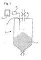
- Fig. 1 shows in a schematic vertical section a container with a level measuring device.
- the level measuring device comprises, in a manner known per se, a transmitter / receiver unit 3 mounted in the interior of the container 1 on its ceiling 2, an evaluation unit 4 connected to the transmitter / receiver unit 3, and a display unit 5, e.g. B. a picture tube.
- the evaluation unit 4 can be implemented as a suitably programmed microprocessor associated with the transceiver unit 3; but it may also be a non-specialized computer, which communicates with the transmitter / receiver unit 3 via an interface (not shown) and is able to execute a program that realizes a method to be described in more detail below.
- the transmitter / receiver unit 3 sends a signal, in particular an ultrasonic signal, into the lower area of the container 1, where is to be detected contents 7, and receives a reflected from the contents 7 and from the walls of the container 1 echo signal.
- Fig. 2 is a graph showing a typical course of such an echo signal.
- the amplitude of the echo signal in decibels is plotted on the abscissa the distance traveled in meters corresponding to the propagation time of the echo signal, and in ordinates the amplitude of the echo signal.
- Two curves 10, 11 show the typical time course of an echo signal in each case in the non-filling operation of the container or in a current filling process. The comparison of the two curves shows that the signal amplitude curve of the curve 11 corresponding to the filling process is lower overall and also has fewer details.
- curves 10 and 11 show that in the case of the container on which these curves were measured, there are significant amplitude differences between the two curves for path lengths of 16-32 m and of about 39-46 m.
- the function p (x) has the value x for positive x and otherwise the value 0.
- Fig. 3 shows a curve 14, formed from a series of values of this sum R, which were recorded on a container over a period of time in which filling operations and stages alternated without filling the container. It can be seen clearly that the values of the sum R lie in two distinct ranges of values S1, S2, depending on whether a filling process is running, as in the intervals d1, d3, d5, or not, as in the intervals d2, d4 ,
Description
Die vorliegende Erfindung betrifft ein Verfahren und eine Vorrichtung zum Erfassen eines Befüllvorgangs.The present invention relates to a method and a device for detecting a filling process.
Zur Überwachung des Füllstands für fließ- oder schüttfähige Materialien werden häufig Sensoren eingesetzt, die ein Signal in den Behälter aussenden, aus dem Behälter zurückgeworfene Signale aufnehmen und durch eine Signalanalyse eine Abschätzung des Füllstandes des Behälters erlauben.To monitor the level of free-flowing or pourable materials sensors are often used to send out a signal in the container, record signals reflected from the container and allow by signal analysis, an estimate of the level of the container.
Diese Sensoren funktionieren befriedigend, solange die Füllstandsverhältnisse im Inneren des Behälters sich nicht zu stark ändern, so dass eine wohl definierte Oberfläche des Füllguts existiert, deren Beitrag zum Echosignal isoliert und ausgewertet werden kann. Eine solche Auswertung wird zwar erschwert durch Echobeiträge, die von den Wänden des Behälters oder Behälteranbauten zurückgeworfen werden, doch können diese Störechobeiträge im allgemeinen dadurch vom Echo des Füllgutspiegels unterschieden werden, dass erstere sich im Laufe der Zeit nur dann ändern, wenn die das Echo zurückwerfende Oberfläche entweder vom Füllgut überdeckt oder wieder freigegeben wird. Das Echo des Füllgutspiegels ist also von Störechos langfristig dadurch unterscheidbar, dass bei ersterem die Laufzeit des Echobeitrags langfristig variabel ist, wohingegen bei letzteren die Laufzeit des Echobeitrags unverändert bleibt und statt dessen die Amplitude variiert.These sensors work satisfactorily, as long as the level conditions inside the container do not change too much, so that a well-defined surface of the medium exists whose contribution to the echo signal can be isolated and evaluated. While such evaluation is hampered by echo contributions reflected from the walls of the container or container attachments, these spurious contributions can generally be distinguished from the echo of the product level by the fact that the former only change over time as the echo recoils Surface either covered by the contents or released again. The echo of the filling material level is therefore distinguishable from false echoes in the long term in that the duration of the echo contribution is variable in the long term, whereas in the latter the duration of the echo contribution remains unchanged and instead the amplitude varies.
Wenn ein solcher Behälter befüllt wird, ändern sich die Echosignalverhältnisse. Durch Staub- bzw. Füllgutpartikel in der Luft kann es zu einer Dämpfung der Signale kommen. Die Amplitude der Störechosignale als auch das Echosignal des Füllgutspiegels ändern sich; Füllgut kann an den Behälterwänden haften bleiben oder von diesen abfallen, so dass Informationen über Störechobeiträge, die zu einem früheren Zeitpunkt gesammelt worden sind, während und nach dem Befüllen nicht mehr notwendigerweise gültig sein müssen. Insbesondere wenn die verwendeten Signale akustische Signale sind, kann das Geräusch des Befüllvorgangs sich dem Echosignal überlagern und Echobeiträge verdecken. Auch der Befüllstrom selber kann, wenn er von dem ausgesendeten Signal getroffen wird, Störechosignale liefern.When such a container is filled, the echo signal ratios change. Dust or Füllgutpartikel in the air can lead to a damping of the signals. The amplitude of the false echo signals as well as the echo signal of the product level change; Fillings may adhere to or fall off the walls of the container, so that information about clutter items collected at an earlier time need not necessarily be valid during and after filling. In particular, when the signals used are acoustic signals, the noise of the filling process can be superimposed on the echo signal and obscure echo contributions. Also, the filling current itself, when hit by the transmitted signal, can provide false echo signals.
Alle diese Einflüsse führen dazu, dass die Füllstandsmessung anhand eines Echosignals unter Verwendung von Algorithmen, die befriedigende Ergebnisse liefern, bei laufender Befüllung unbrauchbare Ergebnisse liefern können. Um ständig über zuverlässige Füllstandsmessewerte zu verfügen, ist es daher notwendig, zur Füllstandsabschätzung aus dem Echosignal unterschiedliche Algorithmen oder Parameter einzusetzen, je nach dem, ob gerade ein Befüllvorgang stattfindet oder nicht.All of these influences mean that level measurement based on an echo signal, using algorithms that provide satisfactory results, can yield unusable results while filling. In order to constantly have reliable fill level measurement values, it is therefore necessary to use different algorithms or parameters for filling level estimation from the echo signal, depending on whether a fill process is taking place or not.
Als Stand der Technik werden die
Wenn die Auswertung der Echosignale automatisch in einer Auswertungseinheit vorgenommen werden soll, ist es daher erforderlich, dieser zusätzlich zum Echosignal auch eine Information darüber zuzuführen, ob gerade ein Befüllvorgang stattfindet oder nicht. Eine solche Information kann z. B. erhalten werden durch Abgreifen eines Stellsignals, das den offenen oder geschlossenen Zustand einer Einfüllklappe des Behälters steuert, von einer Steuereinrichtung der Einfüllklappe oder durch einen an der Klappe angeordneten Positionsgeber. In beiden Fällen ist es erforderlich, dass der Behälter bzw. dessen Steuereinrichtung zum Abgreifen des benötigten Signals vorbereitet sind oder dass an ihnen bauliche Änderungen vorgenommen werden.If the evaluation of the echo signals is to be carried out automatically in an evaluation unit, it is therefore necessary to provide this information in addition to the echo signal, whether or not a filling process is taking place. Such information can z. B. be obtained by tapping a control signal that controls the open or closed state of a filler flap of the container, by a control device of the filler or by a flap arranged on the position sensor. In both cases it is necessary that the Container or its control device are prepared for tapping the required signal or that structural changes are made to them.
Aufgabe der vorliegenden Erfindung ist, ein Verfahren zum Erfassen eines Befüllvorgangs in einem Behälter anzugeben, die solche Anforderungen an den Behälter nicht stellen.The object of the present invention is to provide a method for detecting a filling process in a container that does not impose such requirements on the container.
Die Aufgabe wird gelöst durch ein Verfahren mit den Merkmalen des Patentanspruchs 1.The object is achieved by a method having the features of
Ein erfindungsgemäßes Verfahren zum Betreiben eines Füllstandsmessgerätes zur Überwachung des Füllstandes von fließ- oder schüttfähigen Materialien in einem Behälter, wobei sich das Füllgut in einem unteren Bereich des Behälters weist folgende Schritte auf
- a) Aussenden eines Ultraschall- oder Mikrowellensignals in Richtung Füllgut und Aufzeichnen eines zeitlichen Verlaufs von zurückgeworfenen Echosignalen über eine vorgegebene Zeitspanne, bei nicht laufendem Befüllvorgang,
- b) Ermitteln mindestens eines insbesondere amplitudenabhängigen Parameters durch Addieren von Differenzen von an aufeinanderfolgenden Zeitpunkten aufgenommenen Messwerten der Amplitude aus den zurückgeworfenen Echosignalen, wobei eine Differenz nur dann beim Addieren berücksichtigt wird, wenn die Amplitude des späteren Messwerts höher ist als die des früheren,
- c) Festlegen eines Erwartungsbereiches anhand von Messungen des Parameters bei diversen Füllstandspegeln des Behälters, ohne laufenden Befüllvorgang,
- d) Aussenden des Signals in Richtung Füllgut und Vergleich des oder der Ermitteln des Parameters mit dem oder den in b) ermittelten Parametern und
- e) Feststellen eines laufenden Befüllvorgangs, wenn der oder die Parameter innerhalb eines vorgegebenen Abschnitts eines Weglängenbereiches außerhalb eines des Erwartungsbereichs liegt.
- a) emitting an ultrasonic or microwave signal in the direction of contents and recording a time course of reflected echo signals over a predetermined period of time, when not running the filling process,
- b) determining at least one in particular amplitude-dependent parameter by adding differences of measured values of the amplitude taken from the reflected echo signals at successive times, a difference only being taken into account in the adding when the amplitude of the later measured value is higher than that of the previous one,
- c) definition of an expected range based on measurements of the parameter at various filling level levels of the container, without running filling operation,
- d) transmission of the signal in the direction of contents and comparison of or determining the parameter with the one or more determined in b) parameters and
- e) determining a current filling process, if the or the parameter within a predetermined portion of a path length range is outside of the expectation range.
Um die Grenzen der Erwartungsbereiche zweckmäßig festzulegen, werden Messungen des Parameters durchgeführt, ohne dass ein Befüllvorgang stattfindet, und die Erwartungsbereiche werden anhand der so erhaltenen, für den Nicht-Befüllbetrieb des Behälters typischen Parameterwerte definiert.In order to expediently set the limits of the expectation ranges, measurements of the parameter are performed without a filling process taking place and the expected ranges are defined on the basis of the parameter values thus obtained, which are typical for the non-filling operation of the container.
Diese Messungen werden bei diversen Füllstandspegeln des Behälters durchgeführt Vorzugsweise generieren sich beim Einbau des Gerätes die Parameter im laufenden Betrieb selbständig.These measurements are carried out at various filling level levels of the container. Preferably, during installation of the device, the parameters are generated independently during operation.
Als Parameter geeignet ist das Ausmaß der Amplitudenschwankungen im zeitlichen Verlauf der Echosignale. Diese sind relativ gering, wenn die Echosignale von einem starken Störgeräusch des Befüllvorgangs überlagert sind bzw. die aus dem Behälter zurückgeworfenen Echosignale durch einen Füllgutstrahl gedämpft werden.Suitable as a parameter is the extent of the amplitude fluctuations in the time course of the echo signals. These are relatively small when the echo signals are superimposed by a strong noise of the filling or the echo signals reflected from the container are attenuated by a Füllgutstrahl.
Ein solcher Parameter kann auf einfache Weise erhalten werden durch Addieren von Differenzen von an aufeinanderfolgenden Zeitpunkten aufgenommenen Messwerten der Amplitude der Echosignale.Such a parameter can be easily obtained by adding differences of measured values of the amplitude of the echo signals taken at successive times.
Da die Echoamplitude im allgemeinen im Laufe der Zeit nach dem Aussenden des Signals abfällt, ist es zweckmäßig, beim Berechnen des Parameters nur diejenigen Differenzen zu addieren, bei denen die Amplitude des späteren Messwerts höher ist als die des früheren.Since the echo amplitude generally decays over time after the signal has been transmitted, it is expedient to add only those differences in which the amplitude of the later measured value is higher than that of the previous one when calculating the parameter.
Weitere Merkmale und Vorteile der Erfindung ergeben sich aus der nachfolgenden Beschreibung von Ausführungsbeispielen mit Bezug auf die beigefügten Figuren. Es zeigen:
- Fig. 1
- einen schematischen Schnitt durch einen mit einer Füllstandsmessvorrichtung ausgestatteten Schüttgutbehälter;
- Fig. 2
- den zeitlichen Verlauf der Amplitude eines typischen Echosignals ohne Befüllung und während der Befüllung des Behälters; und
- Fig. 3
- den zeitlichen Verlauf eines Rauhheitsparameters des Echosignals, berechnet für eine Vielzahl von nacheinander erzeugten Echos.
- Fig. 1
- a schematic section through a equipped with a level measuring device bulk goods container;
- Fig. 2
- the time course of the amplitude of a typical echo signal without filling and during the filling of the container; and
- Fig. 3
- the time course of a roughness parameter of the echo signal, calculated for a plurality of successively generated echoes.
Die unterschiedlichen Amplituden dieser zwei Kurven 10, 11 lassen sich in unterschiedlicher Weise zur Beurteilung des Vorliegens eines Befüllungsvorgangs nutzen.The different amplitudes of these two
Der Vergleich der Kurven 10 und 11 zeigt, dass im Fall des Behälters, an dem diese Kurven gemessen wurden, bei Weglängen von 16-32 m und von ca. 39-46 m deutliche Amplitudenunterschiede zwischen den zwei Kurven bestehen.The comparison of
Eine weitere Möglichkeit zum Erfassen eine Befüllungsvorgangs durch Analyse der Echosignale ergibt sich aus der in
Um diese Rauheit zu quantifizieren und vergleichen zu können, wird gemäß einer weiteren Ausgestaltung der Erfindung eine Vielzahl von Abtastwerten h(t1), h(t2), ... des Echosignals aufgenommen, wobei die Abtastzeitpunkte t1, t2, ... mit einer vorgegebenen Schrittweite Dt aufeinanderfolgen, und für jedes Echosignal wird die Summe 
berechnet, wobei die Funktion p(x) den Wert x für positive x und sonst den Wert 0 hat.In order to be able to quantify and compare this roughness, according to a further embodiment of the invention, a plurality of samples h (t1), h (t2), ... of the echo signal are recorded, the sampling times t1, t2, predetermined step width Dt, and for each echo signal is the sum
The function p (x) has the value x for positive x and otherwise the
Fig. 3 zeigt eine Kurve 14, gebildet aus einer Folge von Werten dieser Summe R, die an einem Behälter im Laufe einer Zeit aufgenommen wurden, in denen sich Befüllungsvorgänge und Stadien ohne Befüllung des Behälters abwechselten. Man erkennt deutlich, dass die Werte der Summe R in zwei deutlich von einander getrennten Wertebereichen S1, S2 liegen, je nachdem, ob ein Befüllungsvorgang läuft, wie in den Intervallen d1, d3, d5, oder nicht, wie in den Intervallen d2, d4.Fig. 3 shows a
Die oben als Kriterien für die Erkennung eines Befüllungsvorgangs in Betracht gezogenen Parameter punktuelle Amplitude, gemittelte Amplitude, Rauheit R sowie andere, hier nicht eigens erwähnte, können im Rahmen der vorliegenden Erfindung auch durch ihre zeitliche Ableitung im Laufe aufeinanderfolgender Messvorgänge ersetzt werden. So lässt sich zum Beispiel für die zeitliche Ableitung der Amplitude oder der Rauheit ein Erwartungsbereich angeben, der um Null liegt. Wenn die im Laufe aufeinanderfolgender Messvorgänge beobachtete Änderung des Parameters außerhalb des Erwartungsbereichs liegt, so lässt dies auf einen Befüllungsvorgang schließen.The parameters considered above as criteria for the detection of a filling process punctual amplitude, average amplitude, roughness R and others, not specifically mentioned here, can be replaced in the context of the present invention by their temporal derivative in the course of successive measurement operations. Thus, for example, for the time derivative of the amplitude or the roughness an expectation range can be specified, which is around zero. If the change in the parameter observed in the course of successive measuring operations is outside the expected range, this indicates a filling process.
Claims (1)
- A method of operating a filling level measuring instrument for monitoring the filling level of flowable or pourable materials in a container, wherein the filled material is present in a lower region of the container, with the steps:a) emitting an ultrasonic or microwave signal in the direction of the filled material and plotting a time pattern of reflected echo signals over a pre-set period of time, when the filling procedure is not in operation,b) determining from the reflected echo signals an amplitude-dependent parameter by adding differences of measurement figures of the amplitude recorded at successive points in time, wherein a difference is taken into consideration in the addition only when the amplitude of the later measurement figure is higher than that of the earlier one,c) setting a range of expectation with reference to measurements of the parameter in the case of diverse filling levels of the container, without the filling procedure being in operation,d) emitting the signal in the direction of the filled material and determining the parameter,e) setting a filling procedure in operation when the parameter is outside the range of expectation.
Applications Claiming Priority (2)
| Application Number | Priority Date | Filing Date | Title |
|---|---|---|---|
| DE10139242 | 2001-08-09 | ||
| DE10139242A DE10139242A1 (en) | 2001-08-09 | 2001-08-09 | Method and device for detecting a filling process |
Publications (3)
| Publication Number | Publication Date |
|---|---|
| EP1283412A2 EP1283412A2 (en) | 2003-02-12 |
| EP1283412A3 EP1283412A3 (en) | 2004-06-23 |
| EP1283412B1 true EP1283412B1 (en) | 2013-07-17 |
Family
ID=7694973
Family Applications (1)
| Application Number | Title | Priority Date | Filing Date |
|---|---|---|---|
| EP02011726.3A Expired - Lifetime EP1283412B1 (en) | 2001-08-09 | 2002-05-27 | Method for detecting a filling process |
Country Status (3)
| Country | Link |
|---|---|
| US (1) | US6829932B2 (en) |
| EP (1) | EP1283412B1 (en) |
| DE (1) | DE10139242A1 (en) |
Cited By (1)
| Publication number | Priority date | Publication date | Assignee | Title |
|---|---|---|---|---|
| EP3112821A1 (en) | 2015-07-02 | 2017-01-04 | VEGA Grieshaber KG | Method and device for fill level measurement |
Families Citing this family (7)
| Publication number | Priority date | Publication date | Assignee | Title |
|---|---|---|---|---|
| DE102005011686B4 (en) * | 2005-03-11 | 2020-02-27 | Krohne S.A. | Method for measuring the level of a medium provided in a container on the basis of the radar principle |
| US7819144B2 (en) * | 2005-09-01 | 2010-10-26 | Wotring Blake R | Method and apparatus for loading and conditioning materials |
| US7467548B2 (en) * | 2005-10-14 | 2008-12-23 | Rosemount Tank Radar Ab | Radar level gauge system and coupling |
| DE102012101725A1 (en) * | 2012-03-01 | 2013-09-05 | Sick Ag | Method for level measurement |
| DE102014200924A1 (en) * | 2014-01-20 | 2015-07-23 | Alfons Tschritter Gmbh | Apparatus and method for the promotion of flowable materials, in particular bulk materials |
| DE102018123432A1 (en) * | 2018-09-24 | 2020-03-26 | Endress+Hauser SE+Co. KG | Detection of event-dependent states during level measurement |
| US11867798B2 (en) * | 2019-09-13 | 2024-01-09 | Samsung Electronics Co., Ltd. | Electronic device including sensor and method of determining path of electronic device |
Family Cites Families (21)
| Publication number | Priority date | Publication date | Assignee | Title |
|---|---|---|---|---|
| CH607002A5 (en) * | 1976-06-09 | 1978-11-30 | Endress G H & Co | |
| US4437497A (en) * | 1981-09-23 | 1984-03-20 | Enander Frederick A | Ultrasonic control of filling a container |
| DE3337690A1 (en) | 1983-10-17 | 1985-04-25 | VEGA Grieshaber GmbH & Co, 7620 Wolfach | Method and device for measuring the filling level in a container by means of sound/ultrasonic waves |
| DE3339984A1 (en) * | 1983-11-04 | 1985-05-23 | Endress U. Hauser Gmbh U. Co, 7867 Maulburg | SOUND AND ULTRASONIC DISTANCE MEASURING DEVICE |
| DE3438045C2 (en) * | 1983-11-04 | 1986-12-18 | Endress U. Hauser Gmbh U. Co, 7867 Maulburg | Arrangement for signal transmission in ultrasonic echo sounders |
| US4890266A (en) * | 1987-04-22 | 1989-12-26 | Federal Industries Industrial Group Inc. | Acoustic range finding system |
| DE3822993A1 (en) * | 1988-07-07 | 1990-01-11 | Bosch Gmbh Robert | LEVEL INDICATOR |
| US5131271A (en) * | 1990-04-16 | 1992-07-21 | Magnetrol International, Inc. | Ultrasonic level detector |
| DE4218303C1 (en) * | 1992-06-03 | 1994-03-03 | Endress Hauser Gmbh Co | Method and arrangement for distance measurement according to the pulse transit time principle |
| DE4234300C2 (en) * | 1992-10-12 | 1998-11-26 | Grieshaber Vega Kg | Level measurement method |
| DE4308373C2 (en) * | 1993-03-16 | 1995-04-13 | Siemens Ag | Process for the detection and separation of useful and false echoes in the received signal from distance sensors, which work according to the pulse-echo principle |
| US5337289A (en) * | 1993-07-16 | 1994-08-09 | The United States Of America As Represented By The Department Of Energy | Phased-array ultrasonic surface contour mapping system and method for solids hoppers and the like |
| DE4332071C2 (en) | 1993-09-21 | 1995-09-07 | Endress Hauser Gmbh Co | Level measurement method according to the radar principle |
| US5498867A (en) * | 1993-11-22 | 1996-03-12 | Sachio Uehara | Wavelength-division multiplex digital optical position sensor |
| DE4405238C2 (en) | 1994-02-18 | 1998-07-09 | Endress Hauser Gmbh Co | Arrangement for measuring the level in a container |
| DE19531540C2 (en) * | 1995-08-25 | 1999-05-27 | Krohne Messtechnik Kg | Method for measuring the level of a liquid |
| DE19531662A1 (en) * | 1995-08-29 | 1997-03-06 | Claas Ohg | Device for the automatic filling of loading containers |
| EP0770859A1 (en) * | 1995-10-27 | 1997-05-02 | Endress + Hauser Gmbh + Co. | Calibration method for filling level measurement |
| DE19723646C2 (en) * | 1997-06-05 | 1999-07-29 | Endress Hauser Gmbh Co | Method for measuring the level of a product in a container according to the radar principle |
| EP1014049A3 (en) * | 1998-12-21 | 2001-03-07 | Michael Dipl.-Ing. Horst | Device for liquid level control |
| EP1069438A1 (en) * | 1999-07-15 | 2001-01-17 | Endress + Hauser Gmbh + Co. | Method and device for highly accurate determination of the level of a product in a container |
-
2001
- 2001-08-09 DE DE10139242A patent/DE10139242A1/en not_active Withdrawn
-
2002
- 2002-05-27 EP EP02011726.3A patent/EP1283412B1/en not_active Expired - Lifetime
- 2002-07-25 US US10/202,008 patent/US6829932B2/en not_active Expired - Lifetime
Cited By (1)
| Publication number | Priority date | Publication date | Assignee | Title |
|---|---|---|---|---|
| EP3112821A1 (en) | 2015-07-02 | 2017-01-04 | VEGA Grieshaber KG | Method and device for fill level measurement |
Also Published As
| Publication number | Publication date |
|---|---|
| EP1283412A2 (en) | 2003-02-12 |
| US6829932B2 (en) | 2004-12-14 |
| DE10139242A1 (en) | 2003-03-06 |
| US20030033869A1 (en) | 2003-02-20 |
| EP1283412A3 (en) | 2004-06-23 |
Similar Documents
| Publication | Publication Date | Title |
|---|---|---|
| EP1523661B1 (en) | Method and device for determining an expectancy range for a level echo and a spurious echo | |
| EP2856086B1 (en) | Method for measuring fill-level in accordance with the travel time principle | |
| EP1573278B1 (en) | Filling-level measurement device and method for measuring the filling level according to the propagation time principle | |
| DE4338743C2 (en) | Method and device for operating an ultrasonic sensor | |
| EP1839017B1 (en) | Method for checking the proper functioning of a level indicator | |
| DE4025326C2 (en) | Method and device for measuring the liquid level of a moving liquid in a container | |
| WO2008080840A1 (en) | Method for determining and monitoring the filling level of a medium in a container according to a propagation time measurement method | |
| WO1994022033A1 (en) | Process for recognizing and discriminating between useful and interfering echos in the reception signal of distance sensors working according to the pulse-echo principle | |
| EP0668488A2 (en) | Device for measuring the filling level of a container | |
| EP2223059A1 (en) | Method for filling level measurement | |
| DE3337690A1 (en) | Method and device for measuring the filling level in a container by means of sound/ultrasonic waves | |
| DE4234300C2 (en) | Level measurement method | |
| DE2620590A1 (en) | PROCEDURE FOR ORIFICE SETTING DURING THE AUTOMATED TEST PIECE THICKNESS MEASUREMENT AND / OR NON-DESTRUCTION-FREE MATERIAL TESTING WITH ULTRASOUND | |
| EP1695043B1 (en) | Filling level measurement method according to the running time principle | |
| DE3937585C2 (en) | Distance measuring device | |
| EP1283412B1 (en) | Method for detecting a filling process | |
| WO2006063933A2 (en) | Level gauge operating according to the propagation time principle, and method for the initial operation thereof | |
| DE2753472A1 (en) | PROCEDURE FOR AUTOMATIC SELF-MONITORING OF NON-DESTRUCTION-FREE TESTING SYSTEMS | |
| EP3054271A1 (en) | Limit level switch with integrated position sensor | |
| WO2003102512A1 (en) | Ultrasonic measurement of the running time and quantity for detecting the concentration of particles in a flowing fluid | |
| DE10260959A1 (en) | Level measuring device and method for level measurement | |
| DE4027030C2 (en) | ||
| EP3199926B1 (en) | Method for operating a contactless ultrasonic or radar filling level measuring device | |
| AT401687B (en) | MEASURING METHOD FOR DETECTING THE FILLING QUANTITY OF A STANDARD CONTAINER OD. DGL. | |
| DE4206990A1 (en) | Controlling sideways position of construction or agricultural machine - using pair of ultrasonic detectors to generate control input to e.g. tractor |
Legal Events
| Date | Code | Title | Description |
|---|---|---|---|
| PUAI | Public reference made under article 153(3) epc to a published international application that has entered the european phase |
Free format text: ORIGINAL CODE: 0009012 |
|
| AK | Designated contracting states |
Designated state(s): AT BE CH CY DE DK ES FI FR GB GR IE IT LI LU MC NL PT SE TR |
|
| AX | Request for extension of the european patent |
Extension state: AL LT LV MK RO SI |
|
| PUAL | Search report despatched |
Free format text: ORIGINAL CODE: 0009013 |
|
| AK | Designated contracting states |
Kind code of ref document: A3 Designated state(s): AT BE CH CY DE DK ES FI FR GB GR IE IT LI LU MC NL PT SE TR |
|
| AX | Request for extension of the european patent |
Extension state: AL LT LV MK RO SI |
|
| 17P | Request for examination filed |
Effective date: 20040714 |
|
| AKX | Designation fees paid |
Designated state(s): DE FR GB SE |
|
| RBV | Designated contracting states (corrected) |
Designated state(s): DE FR GB SE |
|
| 17Q | First examination report despatched |
Effective date: 20061215 |
|
| GRAJ | Information related to disapproval of communication of intention to grant by the applicant or resumption of examination proceedings by the epo deleted |
Free format text: ORIGINAL CODE: EPIDOSDIGR1 |
|
| GRAP | Despatch of communication of intention to grant a patent |
Free format text: ORIGINAL CODE: EPIDOSNIGR1 |
|
| GRAS | Grant fee paid |
Free format text: ORIGINAL CODE: EPIDOSNIGR3 |
|
| GRAA | (expected) grant |
Free format text: ORIGINAL CODE: 0009210 |
|
| AK | Designated contracting states |
Kind code of ref document: B1 Designated state(s): DE FR GB SE |
|
| REG | Reference to a national code |
Ref country code: GB Ref legal event code: FG4D Free format text: NOT ENGLISH |
|
| REG | Reference to a national code |
Ref country code: DE Ref legal event code: R096 Ref document number: 50215803 Country of ref document: DE Effective date: 20130912 |
|
| REG | Reference to a national code |
Ref country code: SE Ref legal event code: TRGR |
|
| PLBE | No opposition filed within time limit |
Free format text: ORIGINAL CODE: 0009261 |
|
| STAA | Information on the status of an ep patent application or granted ep patent |
Free format text: STATUS: NO OPPOSITION FILED WITHIN TIME LIMIT |
|
| 26N | No opposition filed |
Effective date: 20140422 |
|
| REG | Reference to a national code |
Ref country code: DE Ref legal event code: R097 Ref document number: 50215803 Country of ref document: DE Effective date: 20140422 |
|
| REG | Reference to a national code |
Ref country code: FR Ref legal event code: PLFP Year of fee payment: 14 |
|
| PGFP | Annual fee paid to national office [announced via postgrant information from national office to epo] |
Ref country code: GB Payment date: 20150521 Year of fee payment: 14 |
|
| PGFP | Annual fee paid to national office [announced via postgrant information from national office to epo] |
Ref country code: FR Payment date: 20150519 Year of fee payment: 14 |
|
| GBPC | Gb: european patent ceased through non-payment of renewal fee |
Effective date: 20160527 |
|
| REG | Reference to a national code |
Ref country code: FR Ref legal event code: ST Effective date: 20170131 |
|
| PG25 | Lapsed in a contracting state [announced via postgrant information from national office to epo] |
Ref country code: FR Free format text: LAPSE BECAUSE OF NON-PAYMENT OF DUE FEES Effective date: 20160531 |
|
| PG25 | Lapsed in a contracting state [announced via postgrant information from national office to epo] |
Ref country code: GB Free format text: LAPSE BECAUSE OF NON-PAYMENT OF DUE FEES Effective date: 20160527 |
|
| PGFP | Annual fee paid to national office [announced via postgrant information from national office to epo] |
Ref country code: SE Payment date: 20180523 Year of fee payment: 17 |
|
| PG25 | Lapsed in a contracting state [announced via postgrant information from national office to epo] |
Ref country code: SE Free format text: LAPSE BECAUSE OF NON-PAYMENT OF DUE FEES Effective date: 20190528 |
|
| REG | Reference to a national code |
Ref country code: SE Ref legal event code: EUG |
|
| PGFP | Annual fee paid to national office [announced via postgrant information from national office to epo] |
Ref country code: DE Payment date: 20210525 Year of fee payment: 20 |
|
| REG | Reference to a national code |
Ref country code: DE Ref legal event code: R071 Ref document number: 50215803 Country of ref document: DE |