EP1283383B1 - Stepless speed change unit - Google Patents
Stepless speed change unit Download PDFInfo
- Publication number
- EP1283383B1 EP1283383B1 EP01906137A EP01906137A EP1283383B1 EP 1283383 B1 EP1283383 B1 EP 1283383B1 EP 01906137 A EP01906137 A EP 01906137A EP 01906137 A EP01906137 A EP 01906137A EP 1283383 B1 EP1283383 B1 EP 1283383B1
- Authority
- EP
- European Patent Office
- Prior art keywords
- belt
- spring
- tension
- ratio
- transmission
- Prior art date
- Legal status (The legal status is an assumption and is not a legal conclusion. Google has not performed a legal analysis and makes no representation as to the accuracy of the status listed.)
- Expired - Lifetime
Links
Images


Classifications
-
- F—MECHANICAL ENGINEERING; LIGHTING; HEATING; WEAPONS; BLASTING
- F16—ENGINEERING ELEMENTS AND UNITS; GENERAL MEASURES FOR PRODUCING AND MAINTAINING EFFECTIVE FUNCTIONING OF MACHINES OR INSTALLATIONS; THERMAL INSULATION IN GENERAL
- F16H—GEARING
- F16H7/00—Gearings for conveying rotary motion by endless flexible members
- F16H7/18—Means for guiding or supporting belts, ropes, or chains
-
- F—MECHANICAL ENGINEERING; LIGHTING; HEATING; WEAPONS; BLASTING
- F16—ENGINEERING ELEMENTS AND UNITS; GENERAL MEASURES FOR PRODUCING AND MAINTAINING EFFECTIVE FUNCTIONING OF MACHINES OR INSTALLATIONS; THERMAL INSULATION IN GENERAL
- F16H—GEARING
- F16H9/00—Gearings for conveying rotary motion with variable gear ratio, or for reversing rotary motion, by endless flexible members
- F16H9/02—Gearings for conveying rotary motion with variable gear ratio, or for reversing rotary motion, by endless flexible members without members having orbital motion
- F16H9/04—Gearings for conveying rotary motion with variable gear ratio, or for reversing rotary motion, by endless flexible members without members having orbital motion using belts, V-belts, or ropes
- F16H9/12—Gearings for conveying rotary motion with variable gear ratio, or for reversing rotary motion, by endless flexible members without members having orbital motion using belts, V-belts, or ropes engaging a pulley built-up out of relatively axially-adjustable parts in which the belt engages the opposite flanges of the pulley directly without interposed belt-supporting members
- F16H9/16—Gearings for conveying rotary motion with variable gear ratio, or for reversing rotary motion, by endless flexible members without members having orbital motion using belts, V-belts, or ropes engaging a pulley built-up out of relatively axially-adjustable parts in which the belt engages the opposite flanges of the pulley directly without interposed belt-supporting members using two pulleys, both built-up out of adjustable conical parts
- F16H9/20—Gearings for conveying rotary motion with variable gear ratio, or for reversing rotary motion, by endless flexible members without members having orbital motion using belts, V-belts, or ropes engaging a pulley built-up out of relatively axially-adjustable parts in which the belt engages the opposite flanges of the pulley directly without interposed belt-supporting members using two pulleys, both built-up out of adjustable conical parts both flanges of the pulleys being adjustable
-
- F—MECHANICAL ENGINEERING; LIGHTING; HEATING; WEAPONS; BLASTING
- F16—ENGINEERING ELEMENTS AND UNITS; GENERAL MEASURES FOR PRODUCING AND MAINTAINING EFFECTIVE FUNCTIONING OF MACHINES OR INSTALLATIONS; THERMAL INSULATION IN GENERAL
- F16H—GEARING
- F16H61/00—Control functions within control units of change-speed- or reversing-gearings for conveying rotary motion ; Control of exclusively fluid gearing, friction gearing, gearings with endless flexible members or other particular types of gearing
- F16H61/66—Control functions within control units of change-speed- or reversing-gearings for conveying rotary motion ; Control of exclusively fluid gearing, friction gearing, gearings with endless flexible members or other particular types of gearing specially adapted for continuously variable gearings
- F16H61/662—Control functions within control units of change-speed- or reversing-gearings for conveying rotary motion ; Control of exclusively fluid gearing, friction gearing, gearings with endless flexible members or other particular types of gearing specially adapted for continuously variable gearings with endless flexible members
- F16H61/66272—Control functions within control units of change-speed- or reversing-gearings for conveying rotary motion ; Control of exclusively fluid gearing, friction gearing, gearings with endless flexible members or other particular types of gearing specially adapted for continuously variable gearings with endless flexible members characterised by means for controlling the torque transmitting capability of the gearing
-
- F—MECHANICAL ENGINEERING; LIGHTING; HEATING; WEAPONS; BLASTING
- F16—ENGINEERING ELEMENTS AND UNITS; GENERAL MEASURES FOR PRODUCING AND MAINTAINING EFFECTIVE FUNCTIONING OF MACHINES OR INSTALLATIONS; THERMAL INSULATION IN GENERAL
- F16H—GEARING
- F16H7/00—Gearings for conveying rotary motion by endless flexible members
- F16H7/08—Means for varying tension of belts, ropes, or chains
- F16H2007/0802—Actuators for final output members
- F16H2007/0808—Extension coil springs
-
- F—MECHANICAL ENGINEERING; LIGHTING; HEATING; WEAPONS; BLASTING
- F16—ENGINEERING ELEMENTS AND UNITS; GENERAL MEASURES FOR PRODUCING AND MAINTAINING EFFECTIVE FUNCTIONING OF MACHINES OR INSTALLATIONS; THERMAL INSULATION IN GENERAL
- F16H—GEARING
- F16H7/00—Gearings for conveying rotary motion by endless flexible members
- F16H7/08—Means for varying tension of belts, ropes, or chains
- F16H2007/0802—Actuators for final output members
- F16H2007/0823—Electric actuators
-
- F—MECHANICAL ENGINEERING; LIGHTING; HEATING; WEAPONS; BLASTING
- F16—ENGINEERING ELEMENTS AND UNITS; GENERAL MEASURES FOR PRODUCING AND MAINTAINING EFFECTIVE FUNCTIONING OF MACHINES OR INSTALLATIONS; THERMAL INSULATION IN GENERAL
- F16H—GEARING
- F16H7/00—Gearings for conveying rotary motion by endless flexible members
- F16H7/08—Means for varying tension of belts, ropes, or chains
- F16H2007/0889—Path of movement of the finally actuated member
- F16H2007/0893—Circular path
-
- F—MECHANICAL ENGINEERING; LIGHTING; HEATING; WEAPONS; BLASTING
- F16—ENGINEERING ELEMENTS AND UNITS; GENERAL MEASURES FOR PRODUCING AND MAINTAINING EFFECTIVE FUNCTIONING OF MACHINES OR INSTALLATIONS; THERMAL INSULATION IN GENERAL
- F16H—GEARING
- F16H7/00—Gearings for conveying rotary motion by endless flexible members
- F16H7/08—Means for varying tension of belts, ropes, or chains
- F16H2007/0889—Path of movement of the finally actuated member
- F16H2007/0897—External to internal direction
-
- F—MECHANICAL ENGINEERING; LIGHTING; HEATING; WEAPONS; BLASTING
- F16—ENGINEERING ELEMENTS AND UNITS; GENERAL MEASURES FOR PRODUCING AND MAINTAINING EFFECTIVE FUNCTIONING OF MACHINES OR INSTALLATIONS; THERMAL INSULATION IN GENERAL
- F16H—GEARING
- F16H7/00—Gearings for conveying rotary motion by endless flexible members
- F16H7/08—Means for varying tension of belts, ropes, or chains
- F16H7/10—Means for varying tension of belts, ropes, or chains by adjusting the axis of a pulley
- F16H7/12—Means for varying tension of belts, ropes, or chains by adjusting the axis of a pulley of an idle pulley
- F16H7/1254—Means for varying tension of belts, ropes, or chains by adjusting the axis of a pulley of an idle pulley without vibration damping means
- F16H7/1281—Means for varying tension of belts, ropes, or chains by adjusting the axis of a pulley of an idle pulley without vibration damping means where the axis of the pulley moves along a substantially circular path
Definitions
- the present invention relates to a continuously variable transmission, and more particularly, it relates to a V belt continuously variable transmission for an automobile, according to the preamble of claim 1.
- a general continuously variable transmission includes a driving pulley, a driven pulley and an endless V belt running across these pulleys, in such a way that the transmission ratio can be continuously variable by changing the running diameters of the belt around the driving pulley and the driven pulley radially in opposite directions.
- the continuously variable transmission can implement smooth driving without shift shock.
- Japanese Unexamined Patent Application Publication JP 5280613 A proposes a continuously variable transmission including actuators for changing the running diameters of a belt around a driving pulley and a driven pulley respectively, a transmission ratio changing mechanism for interlocking the actuators such that the running diameters of the belt around those pulleys are changed radially in opposite directions to each other so as to make the transmission ratio variable, and a tension generating mechanism for pressing the slack side of the belt running across the pulleys so as to have the belt tension larger than that naturally generated depending on the transmission ratio.
- This tension generating mechanism is formed by an arm swingably supported on a transmission case, a tension roller rotatably mounted on one end of the arm and a spring urging the arm so that the tension roller presses the outer surface of the slack side of the belt.
- the tension roller can be arranged not to interfere with either pulley in an initial stage, the position of the tension roller may be varied when the pulleys are worn down or the belt is elongated due to endurance driving test or the like. As a result, the tension roller may come to disadvantageously interfere with the pulleys.
- the closest prior art DE 3838754 A relates to a transmission construction for a pedestrian-operated type work vehicle having an engine at a front of vehicle body and a transmission rearwardly of the engine.
- An engine output shaft and a transmission input shaft are projected laterally from the vehicle body and interconnected via a belt type stepless transmission.
- a change speed operational member of the transmission is disposed within a vehicle front limit defined by an engine cover and a vehicle side limit defined by a belt cover.
- a belt support wheel is interposed in the belt transmission. Consequently, the transmission construction is formed compact yet capable of providing a wide speed range.
- DE 2159018 A relates to a belt control system for adjusting and biasing a cone belt by tension rollers for a infinitely variable change-speed gear having two cone rolls.
- the tension rollers have a common pivot which is shiftable in an actual direction.
- the tension rollers are connected with one or several common springs.
- DE 1136850 B relates to means for measuring and/or evaluating tension variations in a flexible material such as a transmission belt.
- a spring biased member in contact with the flexible material and deflecting the material of the extended position thereof is provided.
- a transmission mechanism is provided between the contact member and the loaded spring. The ratio of transmission of the transmission mechanism is variable such that deflection of the working point of the spring caused by the contact member decreases with increasing approximation of the flexible material to its extended position, such that the movement is substantially or totally linear-proportional to the tension variation of the material.
- the transmission of the present invention comprises a belt running across a driving pulley and a driven pulley, a transmission ratio changing mechanism for changing the running diameters of the belt around the pulleys radially in opposite directions to each other, and a tension-adjusting unit for pressing the belt so as to generate belt tension.
- the tension-adjusting unit includes a tension roller coming into pressure contact with the slack side of the belt from outside, a swing arm swingably mounted on a transmission case, at least one link member for linking the tension roller to the swing arm, and urging means for urging the swing arm in such a direction that the tension roller presses the belt.
- the transmission ratio changing mechanism operates only to change the running diameters of the belt around the driving pulley and the driven pulley radially in opposite directions to each other, whereas the tension-adjusting unit independently operates to generate belt tension so that the belt will not slip on the pulleys.
- the tension-adjusting unit presses the slack side of the belt with the tension roller from outside, thereby generating proper belt tension.
- the belt is prevented from being excessively tensioned, and power transmittal efficiency is improved because the contact areas of the belt running around the pulleys are increased.
- the tension roller of the present invention is mounted on the swing arm, which is swingably supported on the transmission case, not directly but via one or a plurality of link members, whereby support means for the tension roller can be in a linkage structure having at least two degrees of freedom.
- the tension roller can automatically move to a position where it does not interfere with the pulleys at any transmission ratio ranging from the highest to the lowest transmission ratios.
- interference between the tension roller and the pulleys can be reliably prevented even when the pulleys are worn down or the belt is elongated due to endurance driving or the like.
- the distance between the axes of the driving pulley and the driven pulley need not be increased for preventing interference between the tension roller and the pulleys, whereby the size of the transmission body can be miniaturized.
- a rotation axis of the swing arm is preferably provided on a position outside of the driving pulley and closer to the driving pulley than to the driven pulley.
- the rotation axis of the swing arm is provided closer to the driving pulley like this, the angle between the swing arm and the link member is narrower at a low transmission ratio as compared with those angles at a middle transmission ratio and at a high transmission ratio such that the tension roller is strongly pressed against the belt. Therefore, the belt tension can be increased at the low transmission ratio as compared with that at the higher transmission ratios, whereby the power transmittal efficiency is effectively improved and the life span of the belt is increased.
- a first spring and a second spring are provided on the tension-adjusting unit so that joined forces of those two springs are applied to the swing arm.
- the belt pressing force of the first spring is set to be large at the high and the low transmission ratios, and small at the middle transmission ratio.
- the second spring consists of a compression spring having an end rotatably supported on the transmission case and another end rotatably coupled to the swing arm.
- the urging force direction of this second spring also changes such that the rotational force of the swing arm in a direction for pressing the belt caused by this second spring at the middle transmission ratio exceeds those forces at the highest and the lowest transmission ratios.
- the urging force direction of the second spring is changed.
- the belt tension characteristic, which changes in accordance with the transmission ratio, obtained by the second spring is inverse to that obtained by the first spring. Therefore, even if the first spring causes excessive belt tension at the low and the high transmission ratios or insufficient tension at the middle transmission ratio, the belt tension can be reduced at the low and the high transmission ratios or increased at the middle transmission ratio due to the action of the second spring.
- employing the first and second springs together can solve both of the problems with respect to insufficient tension at the middle transmission ratio and excessive tension at the low and the high transmission ratios, thereby providing a desirable belt tension characteristic.
- the middle transmission ratio may not necessarily have just the central transmission ratio between the lowest and the highest transmission ratios, but may have any transmission ratio around the central ratio between the lowest and the highest transmission ratios.
- the second spring is preferably so arranged that a coupling point of the second spring to the swing arm at the highest and the lowest transmission ratio is located opposite to the belt with reference to a straight line connecting an end of the second spring and an end of the swing arm.
- the direction of rotational force of the swing arm caused by the second spring becomes opposite to that caused by the first spring. Consequently, even when the first spring is set to cause excessive belt tension at the lowest and the highest transmission ratios, the second spring can correct the belt tension so as to obtain a desirable tension characteristic.
- Various means can be employed for the transmission ratio changing mechanism according to the present invention.
- the movable sheaves of both pulleys can be operated stably to change the diameters synchronously and radially in opposite directions to each other.
- Figs. 1 to 13 show a continuously variable transmission.
- Figs. 1 to 4 show the specific structure of the continuously variable transmission, and
- Fig. 6 shows the skeleton structure thereof.
- This continuously variable transmission which is employed in a vehicle having a transversely mounted FF (front engine-front drive) drive system, generally comprises a starting clutch 2 driven by an engine output shaft 1, an input shaft 3 forming an output shaft of the clutch 2, a power shaft 4, a driving shaft 10 having a driving pulley 11, a driven shaft 20 having a driven pulley 21, an endless V belt 15 running across the driving pulley 11 and the driven pulley 21, a reduction shaft 30, output shafts 32 coupled with wheels, a ratio-changing motor 40, a tension-adjusting unit (tensioner) 50 and the like.
- the input shaft 3, the power shaft 4, the driving shaft 10, the driven shaft 20, the reduction shaft 30 and the output shafts 32 are non-coaxially arranged in parallel with each other.
- the clutch 2 is formed by a dry clutch, which can be engaged/disengaged and half-engaged by operating a release fork 2a by a clutch control motor (not shown).
- the input shaft 3 is rotatably supported by a transmission case 6 via a bearing, while a forward gear (forward movement gear) 3a and a reverse gear (reverse movement gear) 3b integrally provided on the input shaft 3 are located in a second gear chamber 6c of the transmission case 6.
- the power shaft 4 is extended between the right and left sidewalls of the transmission case 6, such that both ends thereof are rotatably supported by bearings.
- a forward gear (forward movement gear) 4a meshing with the forward gear 3a of the input shaft 3 is integrally provided on an end of the power shaft 4 closer to the engine.
- a reduction gear 4b is fixed to another end of the power shaft 4 opposite to the engine.
- the reduction gear 4b of the power shaft 4 meshes with a reduction gear 10a rotatably supported on an end of the driving shaft 10 opposite to the engine.
- a synchronous forward shifting means 12 provided on the side of the driving shaft 10 opposite to the engine, selectively couples the reduction gear 10a to the driving shaft 10. Namely, the shifting means 12 can be switched to two positions, i.e., to a forward-drive position "D" or a neutral position "N".
- the reduction gears 4b and 10a and the shifting means 12 form a direct drive mechanism 13 for forward movement, which is located in a first gear chamber 6a formed on a side of the transmission case 6 opposite to the engine.
- the first gear chamber 6a is lubricated with oil.
- the driving pulley 11 includes a fixed sheave 11a fixed onto the driving shaft 10, a movable sheave 11b axially movably supported on the driving shaft 10 and an actuator 14 provided at the back of the movable sheave 11b.
- the actuator 14 is arranged to be closer to the engine than the belt 15.
- the actuator 14 is a ball screw that is axially moved by the ratio-changing motor 40.
- the actuator 14 includes a female screw member 14b rotatably supported by the movable sheave 11b via a bearing 14a, a male screw member 14c supported by the transmission case 6, and a ratio-changing gear 14d fixed to the outer periphery of the female screw member 14b.
- the ratio-changing gear 14d is larger in diameter and smaller in thickness than the movable sheave 11b of the driving pulley 11.
- the driven pulley 21 includes a fixed sheave 21a fixed onto the driven shaft 20, a movable sheave 21b axially movably supported by the driven shaft 20 and an actuator 22 provided at the back of the movable sheave 21b.
- the actuator 22 is arranged on a side opposite to the engine beyond the V belt 15.
- the actuator 22, which is also a ball screw similar to the actuator 14 of the driving pulley 11, includes a female screw member 22b rotatably supported by the movable sheave 21b via a bearing 22a, a male screw member 22c supported by the transmission case 6, and a ratio-changing gear 22d fixed to the outer periphery of the female screw member 22b.
- the ratio-changing gear 22d is also larger in diameter and smaller in thickness than the movable sheave 21b of the driven pulley 21.
- a synchronous reverse shifting means 25 selectively couples the gear 24 to the driven shaft 20. Namely, the shifting means 25 can be switched to two positions, i.e. to a reverse position "R” or the neutral position "N".
- the reverse gears 3b and 24 and the shifting means 25 form a direct drive mechanism 26 for reverse movement.
- This reduction gear 27 further meshes with a ring gear 31a of a differential gear unit 31 via a gear 30b integrally formed on the reduction shaft 30.
- the gears 30a and 30b of the reduction shaft 30 and the ring gear 31a form a reduction mechanism 29.
- the wheels are driven via the output shafts 32 provided on the differential gear unit 31.
- the direct drive mechanism 26 for reverse movement, the reduction shaft 30 and the differential gear unit 31 are located in a second gear chamber 6b formed on the side of the transmission case 6 closer to the engine. This gear chamber 6b is lubricated with oil.
- the forward gear 3a of the input shaft 3 and the forward gear 4a of the power shaft 4, which are also located in the gear chamber 6b, are similarly lubricated with oil.
- the first and second gear chambers 6a and 6b of the transmission case 6 are lubricated with oil as hereinabove described.
- the driving pulley 11 and the driven pulley 21 are arranged in a pulley chamber 6c interposed between the first and second gear chambers 6a and 6b.
- the pulley chamber 6c is a non-lubricated space, and the belt 15 is formed by a dry-type belt.
- a supply oil path and a return oil path are provided between those two chambers 6a and 6b.
- the supply oil path and the return oil path are defined by an axial hole 4c of the power shaft 4, and a radial clearance 5 between a second ratio-changing shaft 46 described later and the power shaft 4.
- Each of the axial hole 4c and the radial clearance 5 may define either the supply oil path or the return oil path.
- a shift lever is operated so as to switch the forward shifting means 12 to the forward drive position "D".
- the reverse shifting means 25 is automatically switched to the neutral position "N”.
- power inputted from the clutch 2 via the input shaft 3 is transmitted to the output shaft 32 via the forward gears 3a and 4a, the power shaft 4, the direct drive mechanism 13 for forward movement (the reduction gears 4b and 10a and the shifting means 12), the driving shaft 10, the driving pulley 11, the V-belt 15, the driven pulley 21, the driven shaft 20, the reduction gear 27, the reduction shaft 30 and the differential gear unit 31, as shown by thick arrows.
- the shift lever In the reverse movement, the shift lever is operated to move the reverse shifting means 25 to the reverse position "R". At this time, the forward shifting means 12 is automatically switched to the neutral position "N". As shown in Fig. 8 , power input from the clutch 2 via the input shaft 3 is transmitted to the output shat 32 via the direct drive mechanism 26 for reverse movement (the reverse gears 3b and 24 and the reverse shifting means 25), the driven shaft 20, the reduction gear 27, the reduction shaft 30 and the differential gear unit 31, as shown by thick arrows.
- the tensioner 50 for pressing the slack side of the belt 15 is provided so as to supply belt tension as described later.
- the slack side of the belt alters to the tense side thereof, and hence the tensioner 50 disadvantageously presses the tense side so as to apply excessive load to the belt 15.
- a pulley unit defined by the driving pulley 11, the driven pulley 21 and the belt 15 is driven only in forward movement and not driven in reverse movement. Therefore, no reverse load is applied to the belt 15, whereby the burden on the belt 15 is reduced.
- the ratio-changing motor 40 is mounted on the outer side of the transmission case 6, particularly on a position obliquely above the driving pulley 11.
- the motor 40 is, for example, a servo-motor having a brake 41, and its output gear 42 meshes with a reduction gear 43.
- the gears 42 and 43 are located in a motor housing 44 lubricated with oil, and previously assembled with each other.
- a shaft 43a of the reduction gear 43 projects from the motor housing 44.
- a gear 45a, provided on the first ratio-changing shaft 45, is a trapezoidal gear having a length corresponding to the moving stroke of the movable sheave 11b. This gear 45a meshes with the ratio-changing gear 14d provided on the driving pulley 21.
- the gear 14d responsively rotates so that the movable sheave 11b can be axially moved due to the action of the ball screw (the actuator 14). In other words, the running diameter of the belt 15 around the driving pulley 11 can be continuously changed.
- the ratio-changing gear 14d of the driving pulley 11 also meshes with a first idler gear 46a of a sleeve-shaped second ratio-changing shaft 46 in which the power shaft 4 is rotatably received.
- a second idler gear 46b of the second ratio-changing shaft 46 meshes with the ratio-changing gear 22d of the driven pulley 21.
- the idler gears 46a and 46b are also formed by trapezoidal gears having lengths corresponding to moving strokes of the movable sheaves 11b and 21b, similarly to the gear 45a of the first ratio-changing shaft 45.
- the torque of the ratio-changing motor 40 is transmitted to the ratio-changing gear 22d of the driven pulley 21 via the first ratio-changing shaft 45, the ratio-changing gear 14d of the driving pulley 11 and the second ratio-changing shaft 46. Therefore, the movable sheave 11a of the driving pulley 11 and the movable sheave 21a of the driven pulley 21 can synchronously move in the axial direction so as to change the running diameters of the belt 15 around the pulleys 11 and 21 radially in opposite directions to each other.
- the gear train (42, 43, 45, 14d, 46a, 46b and 22d) for transmitting the torque of the ratio-changing motor 40 are formed by reversible gears, they may be rotated by reactive force of the movable sheaves 11a and 21a due to the belt tension so as to disadvantageously change the transmission ratio. Therefore, the ratio-changing motor 40 is provided with the brake 41 for preventing the gears from undesirable rotation.
- the unit for adjusting tension to the belt 15, i.e., the tensioner 50 is now described.
- the ratio-changing motor 40 as hereinabove described changes the running diameters of the belt 15 around the pulleys 11 and 21.
- the belt 15 may slip with respect to the pulleys 11 and 21 depending on the transmitted torque.
- the tensioner 50 is provided for supplying tension to the belt 15 responsive to the transmitted torque.
- the tensioner 50 includes a tension roller 51, which is swingably supported by a swing arm 53 via a link member 52.
- the swing arm 53 has a rotation axis 53a, which is provided on a portion obliquely above the driving pulley 11, and is urged by a spring 54 toward the belt 15. Therefore, the tension roller 51 inwardly presses the slack side of the belt 15 with prescribed force.
- the tensioner 50 inwardly presses the belt 15 from outside in order to obtain prescribed belt tension as well as to increase the contact areas of the belt 15 around the pulleys 11 and 21, thereby improving the power transmittal efficiency.
- a shaft 52a located on an end of the link 52 is rotatably supported on the forward end of the arm 52, while a shaft 52b located on the other end of the link 52 rotatably supports the central portion of the tension roller 51.
- a gear 53b is formed on the outer peripheral surface of the forward end of the arm 53 so as to mesh with a pinion gear 56 of an assist motor 55 provided for controlling belt tension.
- the aforementioned spring 54 supplies initial tension.
- the assist motor 55 is normally or reversely driven for adding or subtracting tension caused by the assist motor 55 to or from the initial tension so that the optimum belt tension can be obtained. In an automobile having relatively small fluctuation of the transmitted torque, however, the assist motor 55 may be omitted so that only the spring 54 supplies the tension.
- the final belt tension Tb can be rendered variable in the range of 300N to 700N. Therefore, even when the assist motor 55 generates relatively small torque, the belt tension can be varied over a wide range.
- the aforementioned assist motor 55 is controlled by a controller, which is not shown.
- Various signals indicating the rotational speed of the driving shaft 10, the rotational speed of the driven shaft 20, input torque (torque inputted in the driving pulley 11) and the like are inputted into the controller, for controlling the assist motor 55 in response to the input torque or to the transmission ratio.
- the belt tension can be set to arbitrary characteristics shown in Figs. 12 and 13 .
- Fig. 12 shows the relation between the input torque and the tension on the slack side of the belt, which are so set that the belt tension is increased as the input torque is increased.
- the assist motor 55 is controlled in response to the input torque transmitted to the driving pulley 11, for controlling the belt tension to the characteristic shown in Fig. 12 .
- a torque sensor may be provided on the driving shaft 10 for detecting the input torque, or the input torque may be estimated from negative pressure of an engine suction pipe.
- Fig. 13 shows the relation between the transmission ratio and the tension on the slack side of the belt, which are so set that the belt tension is increased at the low range and reduced at the middle and high ranges.
- the engine torque is increased at the low range for starting or uphill driving, and reduced at the high range for high-speed driving.
- the belt tension is preferably set to the minimum necessary level in consideration of the life span of the belt.
- the tension roller 51 is mounted on the arm 53 via the link 52, such that it does not interfere with either pulley 11 or 12.
- the reason for this linkage structure is described with reference to Figs. 9 to 11 . If the tension roller 51 is directly mounted on the arm 53 as in the prior art, the tension roller 51 moves along a rotation locus of the arm 53 about the rotation axis 53a. When the transmission ratio of this continuously variable transmission is changed from the lowest transmission ratio to the highest transmission ratio, the tension roller 51 may interfere with either pulley 11 or 21.
- the tension roller 51 readily interferes with either pulley particularly when the same is prepared from a large-sized roller for reducing the burden applied on the belt 15.
- the tensioner 50 is not restricted to the aforementioned linkage structure having two degrees of freedom, but two links may be employed for attaining a linkage structure having three degrees of freedom.
- the rotation axis 53a of the arm 53 is arranged in the vicinity of the driving pulley 11 for the following reason: vertical pressing force T1 applied from the tension roller 51 to the belt 15 varies depending on the transmission ratio as shown in Figs. 9 to 11 , so as to generate belt tension proportionate to the pressing force T1.
- the pressing force T1 is given by the vector sum of spring force T2 of the spring 54 and force T3 perpendicular thereto. In this case, the urging force of the assist motor 55 is ignored.
- Figs. 14 to 22 show a continuously variable transmission according to an embodiment of the present invention.
- the transmission according to the embodiment is similar in structure to the transmission described above except a tension-adjusting unit (tensioner) 60. Therefore, parts of the embodiment identical to those of the transmission described above are denoted by the same reference numerals, to omit redundant description.
- the feature of the embodiment resides in that a first spring 64 and a second spring 67 are provided on the tensioner 60 in order to apply joined urging force of the springs 64 and 67 to a swing arm 63. In this case, no assist motor is employed.
- the tensioner 60 includes a tension roller 61, which is swingably supported by the arm 63 via a link member 62.
- a rotation axis 63a of the arm 63 is supported on a transmission case 6 above a driving pulley 11.
- a pin 63b to be hooked by an end of the tension spring (first spring) 64 projects from the side surface of the forward end of the arm 63.
- the other end of the tension spring 64 is attached to a shaft 65 provided on the transmission case 6. Therefore, the arm 63 is rotationally urged by the spring 64 so that the tension roller 61 inwardly presses the slack side of an endless V belt 15.
- the tensioner 60 thus inwardly presses the belt 15 from outside in order to obtain prescribed belt tension as well as to increase the contact areas of the belt 15 around the pulleys 11 and 21, thereby improving power transmittal efficiency.
- the link 62 has a pivot or a shaft 62a on an end thereof and the shaft 62a is rotatably supported on the forward end of the arm 62.
- the link 62 also has the other end 62b that supports a central shaft 61a of the tension roller 61.
- a hinge pin or a shaft 63c projects from a side surface of the forward end of the arm 63, and an end of an expansion guide 66 is rotatably coupled to the shaft 63c.
- the other end of the expansion guide 66 is rotatably coupled to a shaft 68 provided on the transmission case 6.
- the compression spring (second spring) 67 is mounted in the expansion guide 66, to be guided by the expansion guide 66 only in an expansion direction, so as not to be distorted or bent when the spring 67 and the guide 66 swing around the shaft 68.
- Figs. 17 , 18 and 19 show motions of the pulley unit at the highest transmission ratio, at the middle transmission ratio and at the lowest transmission ratio respectively.
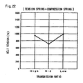
- Figs. 20, 21 and 22 show changes of the belt tension in cases when only the tension spring 64 is used, when only the compression spring 67 is used, and when both of the springs 64 and 67 are used respectively.
- the belt 15 has little allowance in its length at the lowest and highest transmission ratios. Hence the amount of distortion of the belt 15 caused by the tension roller 61 is so small that the tension roller 61 is not dropped between the pulleys 11 and 21. On the other hand, at the middle transmission ratio, the belt 15 has an allowance in its length as shown in Fig. 18 . Hence the amount of distortion of the belt 15 caused by the tension roller 61 is so large that the tension roller 61 is deeply dropped between the pulleys 11 and 21.
- the fulcrum 65 of the tension spring 64 mounted to the transmission case 6 is located opposite to the arm 63 beyond the belt 15. Therefore, the spring force of the tension spring 64 acts in such a direction (direction A) that the tension roller 61 inwardly presses the belt 15. As shown in Fig. 20 , the belt tension caused by the tension spring 64 at the middle transmission ratio is much smaller than those at the high and the low transmission ratios.
- the compression spring 67 is arranged in the vicinity of a straight line L connecting its fulcrum 68 to the transmission case 6 and the rotation axis 63a of the arm 63.
- the coupling point 63c of the compression spring 67 to the arm 63 is located oppositely to the belt 15 beyond the line L at the high and the low transmission ratios, and located closer to the belt 15 than the line L at the middle transmission ratio. Therefore, the spring force of the compression spring 67 acts in a direction (direction B) for separating the tension roller 61 from the belt 15 at the high and the low transmission ratios, and in the direction (direction A) for pressing the belt 15 with the tension roller 61 at the middle transmission ratio.
- the belt tension caused by the compression spring 67 works on the plus side (pressing side) at the middle transmission ratio, whereas it works on the minus side (pulling side) at the high and the low transmission ratios.
- the joined belt tension at the middle transmission ratio is set to the minimum necessary value (e.g., 700N) for preventing slip of the belt 15 on the pulleys
- the joined belt tension at the high and the low transmission ratios can be suppressed to about 950 to 1000N, so as to prevent reaching an excessive level. Therefore, both prevention of slipping of the belt 15 and improvement of the life span of the belt 15 can be compatibly attained.
- the belt tension at the lowest transmission ratio is slightly higher than that at the highest transmission ratio, as shown in Fig. 20 . This is because the rotation axis 63a of the arm 63 is arranged on the side of the driving pulley 11.
- the coupling point 63c of the compression spring 67 to the arm 63 is located opposite to the belt 15 beyond the straight line L at the high and the low transmission ratios and is located closer to the belt 15 than the line L at the middle transmission ratio.
- the present invention is not restricted to this embodiment but the coupling point 63c may be located opposite to the belt 15 beyond the line L or located closer to the belt 15 than the line L regardless of the transmission ratio.
- the coupling point 63c is preferably set to be located opposite to the belt 15 beyond the line L at the lowest and highest transmission ratios so that the belt tension at those ratios can be reduced by the compression spring 67.
- the value of the belt tension caused by the compression spring 67 at the middle transmission ratio may not necessarily be on the plus side (pressing side) but may alternatively be on the minus side or zero.
- the present invention is not restricted to the aforementioned embodiment.
- the rotation axis of the arm 63 may not necessarily be outside of the driving pulley 11, but may be provided coaxially with the driving pulley 11 or with the driven pulley 21.
- one end of the arm 63 is swingably supported on the transmission case 6 and the other end thereof are rotatably coupled to the link 62 respectively in the aforementioned embodiment, the present invention is not restricted to these structures.
- an intermediate portion of the arm 63 may be swingably supported on the transmission case 6, so that the link 62 is coupled to an end and an urging means is coupled to the other end.
- the coupling points of the tension roller 61 to the link 62, and the coupling point of the link 62 to the arm 63 may not necessarily be located on both ends of the link 62.
- the tension spring 64 is employed as the first spring for rotationally urging the arm 63
- a compression spring may alternatively be employed or a torsion spring may be provided on the rotation axis 63a of the arm 63.
- the coupling position of the first spring 64 to the arm 63 may not necessarily be the forward end (the side closer to the tension roller) of the arm 63.
- the first spring 64 may be coupled to the other end of this arm 63, which extends oppositely to the forward end.
Description
- The present invention relates to a continuously variable transmission, and more particularly, it relates to a V belt continuously variable transmission for an automobile, according to the preamble of claim 1.
- In general, various types of continuously variable transmissions are proposed and partially put into practice. A general continuously variable transmission includes a driving pulley, a driven pulley and an endless V belt running across these pulleys, in such a way that the transmission ratio can be continuously variable by changing the running diameters of the belt around the driving pulley and the driven pulley radially in opposite directions. Thus, the continuously variable transmission can implement smooth driving without shift shock.
-
Japanese Unexamined Patent Application Publication JP 5280613 A - However, in the tension generating mechanism having the aforementioned structure, where the tension roller is rotatably mounted on one end of the arm and the arm is urged by the spring for pressing the tension roller against the belt, such a problem may occur that the tension roller disadvantageously interferes with the driving pulley or the driven pulley. This is because the tension roller moves along the rotation locus of the end of the arm. Even if the rotation axis or the length of the arm is so set that the tension roller interferes with neither pulley at the lowest transmission ratio or the lowest vehicle speed ratio, the tension roller may interfere with either pulley at the highest transmission ratio or the highest vehicle speed ratio. Therefore, it is difficult to set the rotation axis or the length of the arm such that the tension roller does not interfere with the pulleys at any transmission ratio. If the distance between the axes of the driving pulley and the driven pulley were increased, the tension roller could be arranged not to interfere with either pulley at any transmission ratio. This case, however, would cause a problem that the size of the transmission body itself is disadvantageously increased.
- Even if the tension roller can be arranged not to interfere with either pulley in an initial stage, the position of the tension roller may be varied when the pulleys are worn down or the belt is elongated due to endurance driving test or the like. As a result, the tension roller may come to disadvantageously interfere with the pulleys.
- The closest prior art
DE 3838754 A relates to a transmission construction for a pedestrian-operated type work vehicle having an engine at a front of vehicle body and a transmission rearwardly of the engine. An engine output shaft and a transmission input shaft are projected laterally from the vehicle body and interconnected via a belt type stepless transmission. A change speed operational member of the transmission is disposed within a vehicle front limit defined by an engine cover and a vehicle side limit defined by a belt cover. Also, a belt support wheel is interposed in the belt transmission. Consequently, the transmission construction is formed compact yet capable of providing a wide speed range. There is also preferably an automatic tensioning wheel. -
DE 2159018 A relates to a belt control system for adjusting and biasing a cone belt by tension rollers for a infinitely variable change-speed gear having two cone rolls. The tension rollers have a common pivot which is shiftable in an actual direction. Moreover, the tension rollers are connected with one or several common springs. -
DE 1136850 B relates to means for measuring and/or evaluating tension variations in a flexible material such as a transmission belt. A spring biased member in contact with the flexible material and deflecting the material of the extended position thereof is provided. A transmission mechanism is provided between the contact member and the loaded spring. The ratio of transmission of the transmission mechanism is variable such that deflection of the working point of the spring caused by the contact member decreases with increasing approximation of the flexible material to its extended position, such that the movement is substantially or totally linear-proportional to the tension variation of the material. - This object can be attained by a continuously variable transmission according to claim 1. The transmission of the present invention comprises a belt running across a driving pulley and a driven pulley, a transmission ratio changing mechanism for changing the running diameters of the belt around the pulleys radially in opposite directions to each other, and a tension-adjusting unit for pressing the belt so as to generate belt tension. The tension-adjusting unit includes a tension roller coming into pressure contact with the slack side of the belt from outside, a swing arm swingably mounted on a transmission case, at least one link member for linking the tension roller to the swing arm, and urging means for urging the swing arm in such a direction that the tension roller presses the belt.
- According to the present invention, the transmission ratio changing mechanism operates only to change the running diameters of the belt around the driving pulley and the driven pulley radially in opposite directions to each other, whereas the tension-adjusting unit independently operates to generate belt tension so that the belt will not slip on the pulleys. The tension-adjusting unit presses the slack side of the belt with the tension roller from outside, thereby generating proper belt tension. When the belt is pressed at its slack side from outside like this, the belt is prevented from being excessively tensioned, and power transmittal efficiency is improved because the contact areas of the belt running around the pulleys are increased.
- The tension roller of the present invention is mounted on the swing arm, which is swingably supported on the transmission case, not directly but via one or a plurality of link members, whereby support means for the tension roller can be in a linkage structure having at least two degrees of freedom. As a result, the tension roller can automatically move to a position where it does not interfere with the pulleys at any transmission ratio ranging from the highest to the lowest transmission ratios. Thus, interference between the tension roller and the pulleys can be reliably prevented even when the pulleys are worn down or the belt is elongated due to endurance driving or the like. Further, the distance between the axes of the driving pulley and the driven pulley need not be increased for preventing interference between the tension roller and the pulleys, whereby the size of the transmission body can be miniaturized.
- As described in
claim 2, a rotation axis of the swing arm is preferably provided on a position outside of the driving pulley and closer to the driving pulley than to the driven pulley. When the rotation axis of the swing arm is provided closer to the driving pulley like this, the angle between the swing arm and the link member is narrower at a low transmission ratio as compared with those angles at a middle transmission ratio and at a high transmission ratio such that the tension roller is strongly pressed against the belt. Therefore, the belt tension can be increased at the low transmission ratio as compared with that at the higher transmission ratios, whereby the power transmittal efficiency is effectively improved and the life span of the belt is increased. - A first spring and a second spring are provided on the tension-adjusting unit so that joined forces of those two springs are applied to the swing arm. The belt pressing force of the first spring is set to be large at the high and the low transmission ratios, and small at the middle transmission ratio. On the other hand, the second spring consists of a compression spring having an end rotatably supported on the transmission case and another end rotatably coupled to the swing arm. When the transmission ratio changes, the urging force direction of this second spring also changes such that the rotational force of the swing arm in a direction for pressing the belt caused by this second spring at the middle transmission ratio exceeds those forces at the highest and the lowest transmission ratios. In other words, by utilizing the swinging of the arm which depends on the transmission ratio, the urging force direction of the second spring is changed.
- In this way, the belt tension characteristic, which changes in accordance with the transmission ratio, obtained by the second spring is inverse to that obtained by the first spring. Therefore, even if the first spring causes excessive belt tension at the low and the high transmission ratios or insufficient tension at the middle transmission ratio, the belt tension can be reduced at the low and the high transmission ratios or increased at the middle transmission ratio due to the action of the second spring. Thus, employing the first and second springs together can solve both of the problems with respect to insufficient tension at the middle transmission ratio and excessive tension at the low and the high transmission ratios, thereby providing a desirable belt tension characteristic.
- The middle transmission ratio may not necessarily have just the central transmission ratio between the lowest and the highest transmission ratios, but may have any transmission ratio around the central ratio between the lowest and the highest transmission ratios.
- As described in claim 3, the second spring is preferably so arranged that a coupling point of the second spring to the swing arm at the highest and the lowest transmission ratio is located opposite to the belt with reference to a straight line connecting an end of the second spring and an end of the swing arm.
- In this case, at the highest and the lowest transmission ratios, the direction of rotational force of the swing arm caused by the second spring becomes opposite to that caused by the first spring. Consequently, even when the first spring is set to cause excessive belt tension at the lowest and the highest transmission ratios, the second spring can correct the belt tension so as to obtain a desirable tension characteristic.
- Various means can be employed for the transmission ratio changing mechanism according to the present invention. As described in claim 4, it is preferable to rotate a ratio-changing gear of the driving pulley and a ratio-changing gear of the driven pulley by means of a single ratio-changing motor via a gear train, such that by the rotation of those ratio-changing gears, ball screws provided on the respective pulleys are driven so as to axially move movable sheaves of the pulleys. In this case, the movable sheaves of both pulleys can be operated stably to change the diameters synchronously and radially in opposite directions to each other.
-
-
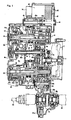
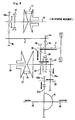
Fig. 1 is an expanded sectional view showing a continuously variable transmission; -
Fig. 2 is a side view of the internal structure of the continuously variable transmission shown inFig. 1 ; -
Fig. 3 is a sectional view of a pulley part of the continuously variable transmission shown inFig. 1 . -
Fig. 4 is an enlarged sectional view taken along the line IV-IV inFig. 3 ; -
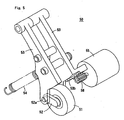
Fig. 5 is a perspective view of an example of the tension-adjusting unit; -
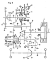
Fig. 6 is a skeleton diagram of the continuously variable transmission shown inFig. 1 ; -
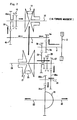
Fig. 7 is a skeleton diagram showing a power flow of the continuously variable transmission in forward movement; -
Fig. 8 is a skeleton diagram showing a power flow of the continuously variable transmission in reverse movement; -
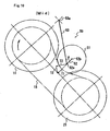
Fig. 9 illustrates a contact position of a tension roller to a belt at a low transmission ratio; -
Fig. 10 illustrates a contact position of the tension roller to a belt at a middle transmission ratio; -
Fig. 11 illustrates a contact position of the roller to a belt at a high transmission ratio; -
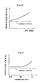
Fig. 12 illustrates the relation between input torque and tension on the slack side of the belt; -
Fig. 13 illustrates the relation between the transmission ratio and the tension on the slack side of the belt; -
Fig. 14 is a sectional view of a pulley part of the continuously variable transmission according to an embodiment of the present invention; -
Fig. 15 is a partially fragmented sectional view of a tension-adjusting unit of the continuously variable transmission shown inFig. 14 ; -
Fig. 16 is a perspective view of a swing arm of the tension-adjusting unit shown inFig. 14 ; -
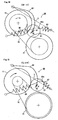
Fig. 17 illustrates a position of contact between a tension roller and a belt at the highest transmission ratio in the continuously variable transmission shown inFig. 14 ; -
Fig. 18 illustrates a position of contact between the tension roller and the belt at the middle transmission ratio in the continuously variable transmission shown inFig. 14 ; -
Fig. 19 illustrates a position of contact between the tension roller and the belt at the lowest transmission ratio in the continuously variable transmission shown inFig. 14 ; -
Fig. 20 illustrates the relation between belt tension and the transmission ratio when only a tension spring is used; -
Fig. 21 illustrates the relation between the belt tension and the transmission ratio when only a compression spring is used; and -
Fig. 22 illustrates the relation between the belt tension and the transmission ratio when both of the tension spring and the compression spring are used. -
Figs. 1 to 13 show a continuously variable transmission.Figs. 1 to 4 show the specific structure of the continuously variable transmission, andFig. 6 shows the skeleton structure thereof. - This continuously variable transmission, which is employed in a vehicle having a transversely mounted FF (front engine-front drive) drive system, generally comprises a starting clutch 2 driven by an engine output shaft 1, an input shaft 3 forming an output shaft of the clutch 2, a power shaft 4, a driving
shaft 10 having a drivingpulley 11, a drivenshaft 20 having a drivenpulley 21, anendless V belt 15 running across the drivingpulley 11 and the drivenpulley 21, areduction shaft 30,output shafts 32 coupled with wheels, a ratio-changingmotor 40, a tension-adjusting unit (tensioner) 50 and the like. The input shaft 3, the power shaft 4, the drivingshaft 10, the drivenshaft 20, thereduction shaft 30 and theoutput shafts 32 are non-coaxially arranged in parallel with each other. - The
clutch 2 is formed by a dry clutch, which can be engaged/disengaged and half-engaged by operating a release fork 2a by a clutch control motor (not shown). - The input shaft 3 is rotatably supported by a
transmission case 6 via a bearing, while a forward gear (forward movement gear) 3a and a reverse gear (reverse movement gear) 3b integrally provided on the input shaft 3 are located in asecond gear chamber 6c of thetransmission case 6. - The power shaft 4 is extended between the right and left sidewalls of the
transmission case 6, such that both ends thereof are rotatably supported by bearings. A forward gear (forward movement gear) 4a meshing with theforward gear 3a of the input shaft 3 is integrally provided on an end of the power shaft 4 closer to the engine. Areduction gear 4b is fixed to another end of the power shaft 4 opposite to the engine. Thereduction gear 4b of the power shaft 4 meshes with areduction gear 10a rotatably supported on an end of the drivingshaft 10 opposite to the engine. Thesegears shaft 10 at a reduction ratio suitable for driving thebelt 15. A synchronous forward shifting means 12, provided on the side of the drivingshaft 10 opposite to the engine, selectively couples thereduction gear 10a to the drivingshaft 10. Namely, the shifting means 12 can be switched to two positions, i.e., to a forward-drive position "D" or a neutral position "N". The reduction gears 4b and 10a and the shifting means 12 form adirect drive mechanism 13 for forward movement, which is located in afirst gear chamber 6a formed on a side of thetransmission case 6 opposite to the engine. Thefirst gear chamber 6a is lubricated with oil. - The driving
pulley 11 includes a fixedsheave 11a fixed onto the drivingshaft 10, amovable sheave 11b axially movably supported on the drivingshaft 10 and anactuator 14 provided at the back of themovable sheave 11b. Theactuator 14 is arranged to be closer to the engine than thebelt 15. According to this embodiment, theactuator 14 is a ball screw that is axially moved by the ratio-changingmotor 40. Theactuator 14 includes afemale screw member 14b rotatably supported by themovable sheave 11b via abearing 14a, amale screw member 14c supported by thetransmission case 6, and a ratio-changinggear 14d fixed to the outer periphery of thefemale screw member 14b. The ratio-changinggear 14d is larger in diameter and smaller in thickness than themovable sheave 11b of the drivingpulley 11. - The driven
pulley 21 includes a fixedsheave 21a fixed onto the drivenshaft 20, amovable sheave 21b axially movably supported by the drivenshaft 20 and anactuator 22 provided at the back of themovable sheave 21b. Theactuator 22 is arranged on a side opposite to the engine beyond theV belt 15. Theactuator 22, which is also a ball screw similar to theactuator 14 of the drivingpulley 11, includes afemale screw member 22b rotatably supported by themovable sheave 21b via abearing 22a, amale screw member 22c supported by thetransmission case 6, and a ratio-changinggear 22d fixed to the outer periphery of thefemale screw member 22b. The ratio-changinggear 22d is also larger in diameter and smaller in thickness than themovable sheave 21b of the drivenpulley 21. - A
reverse gear 24, which is rotatably supported on a portion of the drivenshaft 20 closer to the engine than the drivenpulley 21, meshes with thereverse gear 3b fixed to the input shaft 3. A synchronous reverse shifting means 25 selectively couples thegear 24 to the drivenshaft 20. Namely, the shifting means 25 can be switched to two positions, i.e. to a reverse position "R" or the neutral position "N". The reverse gears 3b and 24 and the shifting means 25 form adirect drive mechanism 26 for reverse movement. - A
reduction gear 27, which is integrally fixed on an end of the drivenshaft 20 closer to the engine, meshes with agear 30a fixed to thereduction shaft 30. Thisreduction gear 27 further meshes with aring gear 31a of adifferential gear unit 31 via agear 30b integrally formed on thereduction shaft 30. Thegears reduction shaft 30 and thering gear 31a form areduction mechanism 29. The wheels are driven via theoutput shafts 32 provided on thedifferential gear unit 31. Thedirect drive mechanism 26 for reverse movement, thereduction shaft 30 and thedifferential gear unit 31 are located in a second gear chamber 6b formed on the side of thetransmission case 6 closer to the engine. This gear chamber 6b is lubricated with oil. Theforward gear 3a of the input shaft 3 and theforward gear 4a of the power shaft 4, which are also located in the gear chamber 6b, are similarly lubricated with oil. - The first and
second gear chambers 6a and 6b of thetransmission case 6 are lubricated with oil as hereinabove described. The drivingpulley 11 and the drivenpulley 21 are arranged in apulley chamber 6c interposed between the first andsecond gear chambers 6a and 6b. According to this embodiment, thepulley chamber 6c is a non-lubricated space, and thebelt 15 is formed by a dry-type belt. - In order to circulate the lubricating oil stored in the first and
second gear chambers 6a and 6b axially separated from each other, a supply oil path and a return oil path are provided between those twochambers 6a and 6b. The supply oil path and the return oil path are defined by anaxial hole 4c of the power shaft 4, and a radial clearance 5 between a second ratio-changingshaft 46 described later and the power shaft 4. Each of theaxial hole 4c and the radial clearance 5 may define either the supply oil path or the return oil path. By circulating the oil though these paths, the clearance 5 between the power shaft 4 and the second ratio-changingshaft 46 can be lubricated as well. - The power flows in forward movement and reverse movement of the continuously variable transmission having the aforementioned structure are described with reference to
Figs. 7 and8 . - In the forward movement, a shift lever is operated so as to switch the forward shifting means 12 to the forward drive position "D". At this time, the reverse shifting means 25 is automatically switched to the neutral position "N". As shown in
Fig. 7 , power inputted from theclutch 2 via the input shaft 3 is transmitted to theoutput shaft 32 via the forward gears 3a and 4a, the power shaft 4, thedirect drive mechanism 13 for forward movement (the reduction gears 4b and 10a and the shifting means 12), the drivingshaft 10, the drivingpulley 11, the V-belt 15, the drivenpulley 21, the drivenshaft 20, thereduction gear 27, thereduction shaft 30 and thedifferential gear unit 31, as shown by thick arrows. - In the reverse movement, the shift lever is operated to move the reverse shifting means 25 to the reverse position "R". At this time, the forward shifting means 12 is automatically switched to the neutral position "N". As shown in
Fig. 8 , power input from theclutch 2 via the input shaft 3 is transmitted to the output shat 32 via thedirect drive mechanism 26 for reverse movement (the reverse gears 3b and 24 and the reverse shifting means 25), the drivenshaft 20, thereduction gear 27, thereduction shaft 30 and thedifferential gear unit 31, as shown by thick arrows. - The
tensioner 50 for pressing the slack side of thebelt 15 is provided so as to supply belt tension as described later. When thebelt 15 is reversely driven, the slack side of the belt alters to the tense side thereof, and hence thetensioner 50 disadvantageously presses the tense side so as to apply excessive load to thebelt 15. According to this embodiment, however, a pulley unit defined by the drivingpulley 11, the drivenpulley 21 and thebelt 15 is driven only in forward movement and not driven in reverse movement. Therefore, no reverse load is applied to thebelt 15, whereby the burden on thebelt 15 is reduced. - A transmission ratio changing mechanism is now described.
- The ratio-changing
motor 40 is mounted on the outer side of thetransmission case 6, particularly on a position obliquely above the drivingpulley 11. Themotor 40 is, for example, a servo-motor having abrake 41, and itsoutput gear 42 meshes with areduction gear 43. Thegears shaft 43a of thereduction gear 43 projects from the motor housing 44. When the motor housing 44 is fixed to thetransmission case 6, theshaft 43a is faucet-engaged with and integrally fixed to a sleeve-shaped first ratio-changingshaft 45 that is rotatably supported on thetransmission case 6. Thus, the motor housing 44 is isolated from the inner space of thetransmission case 6, whereby the lubricating oil stored in the motor housing 44 can be prevented from flowing into thetransmission case 6. Agear 45a, provided on the first ratio-changingshaft 45, is a trapezoidal gear having a length corresponding to the moving stroke of themovable sheave 11b. Thisgear 45a meshes with the ratio-changinggear 14d provided on the drivingpulley 21. When thegear 45a of theshaft 45 is rotated, thegear 14d responsively rotates so that themovable sheave 11b can be axially moved due to the action of the ball screw (the actuator 14). In other words, the running diameter of thebelt 15 around the drivingpulley 11 can be continuously changed. - The ratio-changing
gear 14d of the drivingpulley 11 also meshes with afirst idler gear 46a of a sleeve-shaped second ratio-changingshaft 46 in which the power shaft 4 is rotatably received. Also, asecond idler gear 46b of the second ratio-changingshaft 46 meshes with the ratio-changinggear 22d of the drivenpulley 21. The idler gears 46a and 46b are also formed by trapezoidal gears having lengths corresponding to moving strokes of themovable sheaves gear 45a of the first ratio-changingshaft 45. The torque of the ratio-changingmotor 40 is transmitted to the ratio-changinggear 22d of the drivenpulley 21 via the first ratio-changingshaft 45, the ratio-changinggear 14d of the drivingpulley 11 and the second ratio-changingshaft 46. Therefore, themovable sheave 11a of the drivingpulley 11 and themovable sheave 21a of the drivenpulley 21 can synchronously move in the axial direction so as to change the running diameters of thebelt 15 around thepulleys - When the gear train (42, 43, 45, 14d, 46a, 46b and 22d) for transmitting the torque of the ratio-changing
motor 40 are formed by reversible gears, they may be rotated by reactive force of themovable sheaves motor 40 is provided with thebrake 41 for preventing the gears from undesirable rotation. - The unit for adjusting tension to the
belt 15, i.e., thetensioner 50 is now described. - The ratio-changing
motor 40 as hereinabove described changes the running diameters of thebelt 15 around thepulleys belt 15 may slip with respect to thepulleys Figs. 3 to 5 , therefore, thetensioner 50 is provided for supplying tension to thebelt 15 responsive to the transmitted torque. Thetensioner 50 includes atension roller 51, which is swingably supported by aswing arm 53 via alink member 52. Theswing arm 53 has arotation axis 53a, which is provided on a portion obliquely above the drivingpulley 11, and is urged by aspring 54 toward thebelt 15. Therefore, thetension roller 51 inwardly presses the slack side of thebelt 15 with prescribed force. In this way, thetensioner 50 inwardly presses thebelt 15 from outside in order to obtain prescribed belt tension as well as to increase the contact areas of thebelt 15 around thepulleys shaft 52a located on an end of thelink 52 is rotatably supported on the forward end of thearm 52, while ashaft 52b located on the other end of thelink 52 rotatably supports the central portion of thetension roller 51. Agear 53b is formed on the outer peripheral surface of the forward end of thearm 53 so as to mesh with apinion gear 56 of anassist motor 55 provided for controlling belt tension. - The
aforementioned spring 54 supplies initial tension. Theassist motor 55 is normally or reversely driven for adding or subtracting tension caused by theassist motor 55 to or from the initial tension so that the optimum belt tension can be obtained. In an automobile having relatively small fluctuation of the transmitted torque, however, theassist motor 55 may be omitted so that only thespring 54 supplies the tension. - Assuming that Ts represents belt tension resulting from the spring force of the
spring 54 and Ta represents belt tension caused by theassist motor 55, final belt tension Tb can be expressed as follows:
- For example, assuming that the belt tension Ts is equal to 500N and the belt tension Ta is equal to 200N, the final belt tension Tb can be rendered variable in the range of 300N to 700N. Therefore, even when the
assist motor 55 generates relatively small torque, the belt tension can be varied over a wide range. - The
aforementioned assist motor 55 is controlled by a controller, which is not shown. Various signals indicating the rotational speed of the drivingshaft 10, the rotational speed of the drivenshaft 20, input torque (torque inputted in the driving pulley 11) and the like are inputted into the controller, for controlling theassist motor 55 in response to the input torque or to the transmission ratio. Thus, the belt tension can be set to arbitrary characteristics shown inFigs. 12 and 13 . -
Fig. 12 shows the relation between the input torque and the tension on the slack side of the belt, which are so set that the belt tension is increased as the input torque is increased. - When the input torque is increased, the torque transmitted to the
belt 15 is also increased in general, and hence it is preferable to increase the belt tension for preventing slipping in consideration of the power transmittal efficiency. Therefore, theassist motor 55 is controlled in response to the input torque transmitted to the drivingpulley 11, for controlling the belt tension to the characteristic shown inFig. 12 . A torque sensor may be provided on the drivingshaft 10 for detecting the input torque, or the input torque may be estimated from negative pressure of an engine suction pipe. -
Fig. 13 shows the relation between the transmission ratio and the tension on the slack side of the belt, which are so set that the belt tension is increased at the low range and reduced at the middle and high ranges. In general, the engine torque is increased at the low range for starting or uphill driving, and reduced at the high range for high-speed driving. At the low range, the running diameter of the belt around the driving pulley is small and hence large belt tension is necessary for attaining desirable power transmittal efficiency. On the other hand, at the middle and high ranges that are frequently employed, the belt tension is preferably set to the minimum necessary level in consideration of the life span of the belt. When theassist motor 55 is controlled in response to the transmission ratio so as to set the belt tension to the characteristic as shown inFig. 13 , therefore, desirable characteristic of the belt tension, where good power transmittal efficiency and long life span of the belt can be obtained, will be realized. The transmission ratio can be readily obtained from the ratio of the rotational speed of the driving shaft to the rotational speed of the driven shaft. - In the
aforementioned tensioner 50, thetension roller 51 is mounted on thearm 53 via thelink 52, such that it does not interfere with eitherpulley Figs. 9 to 11 . If thetension roller 51 is directly mounted on thearm 53 as in the prior art, thetension roller 51 moves along a rotation locus of thearm 53 about therotation axis 53a. When the transmission ratio of this continuously variable transmission is changed from the lowest transmission ratio to the highest transmission ratio, thetension roller 51 may interfere with eitherpulley tension roller 51 readily interferes with either pulley particularly when the same is prepared from a large-sized roller for reducing the burden applied on thebelt 15. On the other hand, when thetension roller 51 is mounted on thearm 53 via thelink 52, a linkage structure having two degrees of freedom is attained. In this case, the angle θ between thearm 53 and thelink 52 automatically changes and thetension roller 51 can automatically move to a position where it does not interfere with eitherpulley Fig. 9 , at the middle transmission ratio as shown inFig. 10 and at the highest transmission ratio as shown inFig. 11 respectively. Therefore, interference between thetension roller 51 and eitherpulley tension roller 51 has a large diameter as described in this embodiment. - The
tensioner 50 is not restricted to the aforementioned linkage structure having two degrees of freedom, but two links may be employed for attaining a linkage structure having three degrees of freedom. - The
rotation axis 53a of thearm 53 is arranged in the vicinity of the drivingpulley 11 for the following reason: vertical pressing force T1 applied from thetension roller 51 to thebelt 15 varies depending on the transmission ratio as shown inFigs. 9 to 11 , so as to generate belt tension proportionate to the pressing force T1. The pressing force T1 is given by the vector sum of spring force T2 of thespring 54 and force T3 perpendicular thereto. In this case, the urging force of theassist motor 55 is ignored. When therotation axis 53a of thearm 53 is arranged in the vicinity of the drivingpulley 11 as hereinabove described, the angle θ made between thearm 53 and thelink 52 changes depending on the transmission ratio, so that the pressing force T1 at the middle and the high ranges becomes smaller than that at the low range. Therefore, a belt tension characteristic substantially similar to that shown inFig. 13 can be obtained by using only thespring 54, without theassist motor 55. -
Figs. 14 to 22 show a continuously variable transmission according to an embodiment of the present invention. The transmission according to the embodiment is similar in structure to the transmission described above except a tension-adjusting unit (tensioner) 60. Therefore, parts of the embodiment identical to those of the transmission described above are denoted by the same reference numerals, to omit redundant description. - The feature of the embodiment resides in that a
first spring 64 and asecond spring 67 are provided on thetensioner 60 in order to apply joined urging force of thesprings swing arm 63. In this case, no assist motor is employed. - The
tensioner 60 includes atension roller 61, which is swingably supported by thearm 63 via alink member 62. Arotation axis 63a of thearm 63 is supported on atransmission case 6 above a drivingpulley 11. As shown inFig. 16 , apin 63b to be hooked by an end of the tension spring (first spring) 64 projects from the side surface of the forward end of thearm 63. The other end of thetension spring 64 is attached to ashaft 65 provided on thetransmission case 6. Therefore, thearm 63 is rotationally urged by thespring 64 so that thetension roller 61 inwardly presses the slack side of anendless V belt 15. Thetensioner 60 thus inwardly presses thebelt 15 from outside in order to obtain prescribed belt tension as well as to increase the contact areas of thebelt 15 around thepulleys link 62 has a pivot or ashaft 62a on an end thereof and theshaft 62a is rotatably supported on the forward end of thearm 62. Thelink 62 also has theother end 62b that supports acentral shaft 61a of thetension roller 61. A hinge pin or ashaft 63c projects from a side surface of the forward end of thearm 63, and an end of anexpansion guide 66 is rotatably coupled to theshaft 63c. The other end of theexpansion guide 66 is rotatably coupled to ashaft 68 provided on thetransmission case 6. The compression spring (second spring) 67 is mounted in theexpansion guide 66, to be guided by theexpansion guide 66 only in an expansion direction, so as not to be distorted or bent when thespring 67 and theguide 66 swing around theshaft 68. - Operation of the belt pressing force of the
tension roller 61 caused by thetension spring 64 and thecompression spring 67 depending on the transmission ratio is now described with reference toFigs. 17 to 22 . -
Figs. 17 ,18 and 19 show motions of the pulley unit at the highest transmission ratio, at the middle transmission ratio and at the lowest transmission ratio respectively.Figs. 20, 21 and22 show changes of the belt tension in cases when only thetension spring 64 is used, when only thecompression spring 67 is used, and when both of thesprings - As
Figs. 17 and19 clearly show, thebelt 15 has little allowance in its length at the lowest and highest transmission ratios. Hence the amount of distortion of thebelt 15 caused by thetension roller 61 is so small that thetension roller 61 is not dropped between thepulleys belt 15 has an allowance in its length as shown inFig. 18 . Hence the amount of distortion of thebelt 15 caused by thetension roller 61 is so large that thetension roller 61 is deeply dropped between thepulleys - The
fulcrum 65 of thetension spring 64 mounted to thetransmission case 6 is located opposite to thearm 63 beyond thebelt 15. Therefore, the spring force of thetension spring 64 acts in such a direction (direction A) that thetension roller 61 inwardly presses thebelt 15. As shown inFig. 20 , the belt tension caused by thetension spring 64 at the middle transmission ratio is much smaller than those at the high and the low transmission ratios. - On the other hand, the
compression spring 67 is arranged in the vicinity of a straight line L connecting itsfulcrum 68 to thetransmission case 6 and therotation axis 63a of thearm 63. Thecoupling point 63c of thecompression spring 67 to thearm 63 is located oppositely to thebelt 15 beyond the line L at the high and the low transmission ratios, and located closer to thebelt 15 than the line L at the middle transmission ratio.
Therefore, the spring force of thecompression spring 67 acts in a direction (direction B) for separating thetension roller 61 from thebelt 15 at the high and the low transmission ratios, and in the direction (direction A) for pressing thebelt 15 with thetension roller 61 at the middle transmission ratio. In other words, as shown inFig. 21 , the belt tension caused by thecompression spring 67 works on the plus side (pressing side) at the middle transmission ratio, whereas it works on the minus side (pulling side) at the high and the low transmission ratios. - As a result, when the belt tensions caused by the
springs Fig. 22 . For example, when the joined belt tension at the middle transmission ratio is set to the minimum necessary value (e.g., 700N) for preventing slip of thebelt 15 on the pulleys, the joined belt tension at the high and the low transmission ratios can be suppressed to about 950 to 1000N, so as to prevent reaching an excessive level. Therefore, both prevention of slipping of thebelt 15 and improvement of the life span of thebelt 15 can be compatibly attained. - Although the amounts of distortion of the
tension spring 64 at the highest and the lowest transmission ratios are the same, the belt tension at the lowest transmission ratio is slightly higher than that at the highest transmission ratio, as shown inFig. 20 . This is because therotation axis 63a of thearm 63 is arranged on the side of the drivingpulley 11. - In this embodiment, the
coupling point 63c of thecompression spring 67 to thearm 63 is located opposite to thebelt 15 beyond the straight line L at the high and the low transmission ratios and is located closer to thebelt 15 than the line L at the middle transmission ratio. However, the present invention is not restricted to this embodiment but thecoupling point 63c may be located opposite to thebelt 15 beyond the line L or located closer to thebelt 15 than the line L regardless of the transmission ratio. - When the tension caused by the
tension spring 64 reaches an excessive level at the highest and the lowest transmission ratios as shown inFig. 20 , however, thecoupling point 63c is preferably set to be located opposite to thebelt 15 beyond the line L at the lowest and highest transmission ratios so that the belt tension at those ratios can be reduced by thecompression spring 67. - The value of the belt tension caused by the
compression spring 67 at the middle transmission ratio may not necessarily be on the plus side (pressing side) but may alternatively be on the minus side or zero. - The present invention is not restricted to the aforementioned embodiment.
- For example, the rotation axis of the
arm 63 may not necessarily be outside of the drivingpulley 11, but may be provided coaxially with the drivingpulley 11 or with the drivenpulley 21. - Although one end of the
arm 63 is swingably supported on thetransmission case 6 and the other end thereof are rotatably coupled to thelink 62 respectively in the aforementioned embodiment, the present invention is not restricted to these structures. For example, an intermediate portion of thearm 63 may be swingably supported on thetransmission case 6, so that thelink 62 is coupled to an end and an urging means is coupled to the other end. - Similarly, the coupling points of the
tension roller 61 to thelink 62, and the coupling point of thelink 62 to thearm 63 may not necessarily be located on both ends of thelink 62. - Though the
tension spring 64 is employed as the first spring for rotationally urging thearm 63, a compression spring may alternatively be employed or a torsion spring may be provided on therotation axis 63a of thearm 63. The coupling position of thefirst spring 64 to thearm 63 may not necessarily be the forward end (the side closer to the tension roller) of thearm 63. When an intermediate portion of thearm 63 is swingably supported on thetransmission case 6, thefirst spring 64 may be coupled to the other end of thisarm 63, which extends oppositely to the forward end.
Claims (4)
- A continuously variable transmission comprising an endless belt (15) running across a driving pulley (11) and a driven pulley (21), a transmission ratio changing mechanism for changing the running diameters of said belt (15) around said pulleys (11, 21) radially in opposite directions to each other and a tension-adjusting unit (60) for pressing said belt (15) to obtain belt tension, wherein
said tension-adjusting unit (60) includes:a tension roller (61) coming into pressure contact with the slack side of said belt (15) from outside,a swing arm (63) swingably mounted on a transmission case,at least one link member (62) for linking said tension roller (61) to said swing arm (63), andurging means (64, 67) for swingingly urging said swing arm (63) in such a direction that said tension roller (61) presses said belt (15),characterized in that said urging means for swingingly urging said swing arm (63) includes:a first spring (64) for swingingly urging said swing arm (63) in such a direction that said tension roller (61) presses said belt (15) such that the urging force of said first spring (64) at a highest transmission ratio and a lowest transmission ratio exceeds the urging force of said first spring (64) at a middle transmission ratio, anda second spring (67) formed by a compression spring having an end rotatably supported on said transmission case (6) and another end rotatably coupled to said swing arm (63), whereinsaid second spring (67) is provided on a position where its urging force direction changes depending on the transmission ratio such that the rotational force of said swing arm (63) in a direction for pressing said belt caused by said second spring (67) at the middle transmission ratio exceeds the rotational forces of said swing arm (63) in the direction for pressing said belt caused by said second spring (67) at the highest transmission ratio and the lowest transmission ratio. - The continuously variable transmission according to claim 1, wherein a rotation axis (63a) of said swing arm (63) is provided on a position outside of said driving pulley (11) and closer to said driving pulley (11) than to said driven pulley (21).
- The continuously variable transmission according to claim 1, wherein said second spring (67) is so arranged that a coupling point (63c) of said second spring (67) to said swing arm (63) at the highest transmission ratio and the lowest transmission ratio is located opposite to said belt (15) with reference to a straight line (L) connecting a fulcrum (68) of said second spring (67) and said rotation axis (63a) of said swing arm (63).
- The continuously variable transmission according to any of claims 1 to 3, wherein said transmission ratio changing mechanism includes a ratio-changing motor (40), a first ball screw (14) axially moving a movable sheave (11b) of said driving pulley (11) by rotation of a ratio-changing gear (14d), a second ball screw (22) axially moving a movable sheave (21b) of said driven pulley (21) by rotation of a ratio-changing gear (22d), and a gear train (42, 43, 45, 46) transmitting the torque of said ratio-changing motor (40) to said ratio-changing gears (14d, 22d) of said driving pulley and said driven pulley.
Applications Claiming Priority (3)
| Application Number | Priority Date | Filing Date | Title |
|---|---|---|---|
| JP2000147549 | 2000-05-19 | ||
| JP2000147549A JP3267596B2 (en) | 2000-05-19 | 2000-05-19 | Continuously variable transmission |
| PCT/JP2001/001175 WO2001088411A1 (en) | 2000-05-19 | 2001-02-19 | Stepless speed change unit |
Publications (3)
| Publication Number | Publication Date |
|---|---|
| EP1283383A1 EP1283383A1 (en) | 2003-02-12 |
| EP1283383A4 EP1283383A4 (en) | 2003-07-23 |
| EP1283383B1 true EP1283383B1 (en) | 2008-04-23 |
Family
ID=18653717
Family Applications (1)
| Application Number | Title | Priority Date | Filing Date |
|---|---|---|---|
| EP01906137A Expired - Lifetime EP1283383B1 (en) | 2000-05-19 | 2001-02-19 | Stepless speed change unit |
Country Status (8)
| Country | Link |
|---|---|
| US (1) | US6884191B2 (en) |
| EP (1) | EP1283383B1 (en) |
| JP (1) | JP3267596B2 (en) |
| KR (1) | KR100468959B1 (en) |
| CN (1) | CN1180189C (en) |
| AU (1) | AU2001234093A1 (en) |
| DE (1) | DE60133732T2 (en) |
| WO (1) | WO2001088411A1 (en) |
Families Citing this family (20)
| Publication number | Priority date | Publication date | Assignee | Title |
|---|---|---|---|---|
| US6902502B2 (en) * | 2001-09-06 | 2005-06-07 | Daihatsu Motor Co., Ltd. | Continuously variable transmission |
| EP1464870B1 (en) * | 2003-04-02 | 2012-08-29 | DAYCO EUROPE S.r.l. | Drive assembly for driving a rotary member, in particular a combustion engine water pump shaft |
| FR2865518A1 (en) * | 2004-01-26 | 2005-07-29 | Hutchinson | Handle reversible movement controlling method for power transmission system, involves rotating movable fulcrum pin around another pin whose axes are parallel by off-centering axes of one pin with respect to another |
| JP2007071254A (en) * | 2005-09-05 | 2007-03-22 | Yamaha Motor Co Ltd | V-belt type continuously variable transmission and riding type vehicle |
| JP2007071253A (en) * | 2005-09-05 | 2007-03-22 | Yamaha Motor Co Ltd | Riding type vehicle and power unit |
| US8109849B1 (en) * | 2006-03-06 | 2012-02-07 | Honda Motor Co., Ltd. | Device for releasing tension from auto tensioning cylinder |
| EP2126421A1 (en) * | 2006-12-27 | 2009-12-02 | Robert Bosch GmbH | Continuously variable transmission |
| KR101428067B1 (en) * | 2008-04-08 | 2014-08-07 | 현대자동차주식회사 | Play measurement apparatus and method for pulley of CVT |
| CN103180642B (en) * | 2010-10-18 | 2016-08-17 | 舍弗勒技术股份两合公司 | Buncher |
| CN102287505B (en) * | 2011-08-01 | 2014-06-04 | 李凯 | High-torque stepless speed changer |
| CN104776189A (en) * | 2015-05-04 | 2015-07-15 | 周玉红 | Driving guide wheel adjusting mechanism |
| US9618099B2 (en) * | 2015-07-13 | 2017-04-11 | Gates Corporation | Tensioner with secondary damping |
| US9863512B2 (en) * | 2015-08-12 | 2018-01-09 | Deere & Company | Continuously variable transmission belt guide |
| CN105546065A (en) * | 2016-02-01 | 2016-05-04 | 江苏苏净集团有限公司 | Rotary wheel driving device and rotary wheel dehumidifier |
| JP6428733B2 (en) * | 2016-09-13 | 2018-11-28 | トヨタ自動車株式会社 | Control device for chain belt type continuously variable transmission for vehicle |
| KR102552020B1 (en) * | 2018-10-19 | 2023-07-05 | 현대자동차 주식회사 | Tensioner for hybrid electric vehicle |
| US11499607B2 (en) * | 2019-04-25 | 2022-11-15 | Johnson Controls Tyco IP Holdings LLP | Drive belt tensioner systems and methods |
| CN110863951B (en) * | 2019-12-20 | 2023-12-22 | 湖北科技学院 | Rotating speed control system of small wind driven generator |
| TR202015361A2 (en) * | 2020-09-28 | 2020-10-21 | Bursa Uludag Ueniversitesi | Control Mechanism Developed for Continuously Variable Transfer (CVT) System |
| US11906108B1 (en) * | 2022-07-29 | 2024-02-20 | Deere & Company | Belt trap with integrated tensioner |
Family Cites Families (18)
| Publication number | Priority date | Publication date | Assignee | Title |
|---|---|---|---|---|
| DE1136850B (en) | 1960-06-02 | 1962-09-20 | Elisabeth Kyra Casagrande | Device for measuring and / or evaluating voltage changes in a flexible material |
| DE2159018A1 (en) | 1971-11-29 | 1973-05-30 | Rudolf Peschke | CONTROL DEVICE FOR A BEVEL BELT DRIVE |
| JPS6069859A (en) | 1983-09-26 | 1985-04-20 | Mita Ind Co Ltd | File management system |
| JPS6069859U (en) * | 1983-10-19 | 1985-05-17 | ヤンマー農機株式会社 | Transmission device for agricultural machinery |
| KR930000801B1 (en) | 1987-11-17 | 1993-02-05 | 구보다 뎃꼬오 가부시끼가이샤 | Transmission construction for pedestrian-operated type work vehicle |
| JPH02107859A (en) | 1988-07-07 | 1990-04-19 | Toyota Motor Corp | Planetary gear device |
| FR2636522A1 (en) | 1988-09-21 | 1990-03-23 | Kaysersberg Sa | PERIODIC TOWEL |
| JPH02107859U (en) * | 1989-02-13 | 1990-08-28 | ||
| JPH02121664U (en) * | 1989-03-17 | 1990-10-03 | ||
| JPH03199719A (en) | 1989-12-28 | 1991-08-30 | Aisin Aw Co Ltd | Ball spline device |
| CN2077576U (en) | 1990-10-21 | 1991-05-22 | 吴瑞镛 | Self-tension device for driving belt of phonograph |
| JPH05106700A (en) | 1991-10-14 | 1993-04-27 | Kubota Corp | Continuously variable belt transmission |
| JP2840157B2 (en) | 1992-03-31 | 1998-12-24 | バンドー化学株式会社 | Continuously variable transmission |
| JP3149557B2 (en) * | 1992-08-07 | 2001-03-26 | アイシン・エィ・ダブリュ株式会社 | Belt type continuously variable transmission |
| JP2922728B2 (en) * | 1992-09-08 | 1999-07-26 | 株式会社クボタ | Transmission linkage for work vehicle |
| US5286233A (en) * | 1993-02-24 | 1994-02-15 | Engelstad Jonathan L | Electric control of a harvester fan |
| DE19634343C2 (en) * | 1996-08-24 | 2003-01-02 | Daimler Chrysler Ag | Clamping device for traction means with fixed clamping path |
| DE19822632A1 (en) | 1998-05-20 | 1999-11-25 | Mannesmann Sachs Ag | Device for increasing the stiffness of a tension device in continuously variable tension device gearbox |
-
2000
- 2000-05-19 JP JP2000147549A patent/JP3267596B2/en not_active Expired - Fee Related
-
2001
- 2001-02-19 WO PCT/JP2001/001175 patent/WO2001088411A1/en active IP Right Grant
- 2001-02-19 US US10/148,203 patent/US6884191B2/en not_active Expired - Fee Related
- 2001-02-19 CN CNB018038182A patent/CN1180189C/en not_active Expired - Fee Related
- 2001-02-19 EP EP01906137A patent/EP1283383B1/en not_active Expired - Lifetime
- 2001-02-19 AU AU2001234093A patent/AU2001234093A1/en not_active Abandoned
- 2001-02-19 DE DE60133732T patent/DE60133732T2/en not_active Expired - Lifetime
- 2001-02-19 KR KR10-2002-7011608A patent/KR100468959B1/en not_active IP Right Cessation
Also Published As
| Publication number | Publication date |
|---|---|
| KR100468959B1 (en) | 2005-02-02 |
| US20020183149A1 (en) | 2002-12-05 |
| DE60133732T2 (en) | 2009-05-14 |
| JP3267596B2 (en) | 2002-03-18 |
| DE60133732D1 (en) | 2008-06-05 |
| CN1395661A (en) | 2003-02-05 |
| US6884191B2 (en) | 2005-04-26 |
| CN1180189C (en) | 2004-12-15 |
| AU2001234093A1 (en) | 2001-11-26 |
| WO2001088411A1 (en) | 2001-11-22 |
| EP1283383A4 (en) | 2003-07-23 |
| KR20030009377A (en) | 2003-01-29 |
| JP2001330097A (en) | 2001-11-30 |
| EP1283383A1 (en) | 2003-02-12 |
Similar Documents
| Publication | Publication Date | Title |
|---|---|---|
| EP1283383B1 (en) | Stepless speed change unit | |
| US6902502B2 (en) | Continuously variable transmission | |
| EP0967413B1 (en) | Toroidal continuously variable transmission | |
| KR101114597B1 (en) | Continuously variable transmission | |
| US5662547A (en) | Continuously variable transmission | |
| EP0383282B1 (en) | Pulley type speed-shifting device | |
| US5674150A (en) | Control apparatus for transmission | |
| US6317672B1 (en) | Controller for infinite speed ratio transmission | |
| EP1245865B1 (en) | Toroidal type continuously variable transmission | |
| US20050192134A1 (en) | Step motor arrangement in belt-type continuously variable transmission | |
| US5792019A (en) | Continuously variable transmission with torque converter for a vehicle and hydraulic control system for controlling the same | |
| JPH07122452B2 (en) | V-belt type continuously variable transmission | |
| JP3712345B2 (en) | Continuously variable transmission | |
| US6432019B1 (en) | Hydraulic circuit for toroidal continuous variable transmission | |
| JP3652218B2 (en) | Continuously variable transmission | |
| JP3290647B1 (en) | Continuously variable transmission | |
| JPH0743013B2 (en) | V-belt type continuously variable transmission | |
| KR100460903B1 (en) | Continuously variable transmission for vehicles | |
| JP2665443B2 (en) | Continuously variable transmission | |
| JP2583731B2 (en) | Continuously variable transmission | |
| JPH1122798A (en) | Belt type continuously variable transmission | |
| JP2583732B2 (en) | Continuously variable transmission | |
| KR100313808B1 (en) | Belt-type continuously variable transmission | |
| KR0168391B1 (en) | Cvt for a vehicle | |
| JP2001330094A (en) | Continuously variable transmission |
Legal Events
| Date | Code | Title | Description |
|---|---|---|---|
| PUAI | Public reference made under article 153(3) epc to a published international application that has entered the european phase |
Free format text: ORIGINAL CODE: 0009012 |
|
| 17P | Request for examination filed |
Effective date: 20020612 |
|
| AK | Designated contracting states |
Designated state(s): AT BE CH CY DE DK ES FI FR GB GR IE IT LI LU MC NL PT SE TR |
|
| A4 | Supplementary search report drawn up and despatched |
Effective date: 20030605 |
|
| RIC1 | Information provided on ipc code assigned before grant |
Ipc: 7F 16H 9/18 B Ipc: 7F 16H 7/12 A Ipc: 7F 16H 9/14 B |
|
| 17Q | First examination report despatched |
Effective date: 20030926 |
|
| RBV | Designated contracting states (corrected) |
Designated state(s): AT BE CH DE FR GB LI |
|
| GRAP | Despatch of communication of intention to grant a patent |
Free format text: ORIGINAL CODE: EPIDOSNIGR1 |
|
| RBV | Designated contracting states (corrected) |
Designated state(s): DE FR GB |
|
| GRAS | Grant fee paid |
Free format text: ORIGINAL CODE: EPIDOSNIGR3 |
|
| GRAA | (expected) grant |
Free format text: ORIGINAL CODE: 0009210 |
|
| AK | Designated contracting states |
Kind code of ref document: B1 Designated state(s): DE FR GB |
|
| REG | Reference to a national code |
Ref country code: GB Ref legal event code: FG4D |
|
| REF | Corresponds to: |
Ref document number: 60133732 Country of ref document: DE Date of ref document: 20080605 Kind code of ref document: P |
|
| ET | Fr: translation filed | ||
| PLBE | No opposition filed within time limit |
Free format text: ORIGINAL CODE: 0009261 |
|
| STAA | Information on the status of an ep patent application or granted ep patent |
Free format text: STATUS: NO OPPOSITION FILED WITHIN TIME LIMIT |
|
| 26N | No opposition filed |
Effective date: 20090126 |
|
| PGFP | Annual fee paid to national office [announced via postgrant information from national office to epo] |
Ref country code: FR Payment date: 20100223 Year of fee payment: 10 |
|
| PGFP | Annual fee paid to national office [announced via postgrant information from national office to epo] |
Ref country code: GB Payment date: 20100202 Year of fee payment: 10 Ref country code: DE Payment date: 20100226 Year of fee payment: 10 |
|
| GBPC | Gb: european patent ceased through non-payment of renewal fee |
Effective date: 20110219 |
|
| REG | Reference to a national code |
Ref country code: FR Ref legal event code: ST Effective date: 20111102 |
|
| REG | Reference to a national code |
Ref country code: DE Ref legal event code: R119 Ref document number: 60133732 Country of ref document: DE Effective date: 20110901 |
|
| PG25 | Lapsed in a contracting state [announced via postgrant information from national office to epo] |
Ref country code: FR Free format text: LAPSE BECAUSE OF NON-PAYMENT OF DUE FEES Effective date: 20110228 |
|
| PG25 | Lapsed in a contracting state [announced via postgrant information from national office to epo] |
Ref country code: GB Free format text: LAPSE BECAUSE OF NON-PAYMENT OF DUE FEES Effective date: 20110219 |
|
| PG25 | Lapsed in a contracting state [announced via postgrant information from national office to epo] |
Ref country code: DE Free format text: LAPSE BECAUSE OF NON-PAYMENT OF DUE FEES Effective date: 20110901 |