EP1283071A2 - Monitoring of chemical reactions in channels of a micro-reactor - Google Patents
Monitoring of chemical reactions in channels of a micro-reactor Download PDFInfo
- Publication number
- EP1283071A2 EP1283071A2 EP02254629A EP02254629A EP1283071A2 EP 1283071 A2 EP1283071 A2 EP 1283071A2 EP 02254629 A EP02254629 A EP 02254629A EP 02254629 A EP02254629 A EP 02254629A EP 1283071 A2 EP1283071 A2 EP 1283071A2
- Authority
- EP
- European Patent Office
- Prior art keywords
- reaction
- chemical
- channels
- channel
- fluid
- Prior art date
- Legal status (The legal status is an assumption and is not a legal conclusion. Google has not performed a legal analysis and makes no representation as to the accuracy of the status listed.)
- Granted
Links
Images

Classifications
-
- B—PERFORMING OPERATIONS; TRANSPORTING
- B01—PHYSICAL OR CHEMICAL PROCESSES OR APPARATUS IN GENERAL
- B01J—CHEMICAL OR PHYSICAL PROCESSES, e.g. CATALYSIS OR COLLOID CHEMISTRY; THEIR RELEVANT APPARATUS
- B01J19/00—Chemical, physical or physico-chemical processes in general; Their relevant apparatus
- B01J19/0093—Microreactors, e.g. miniaturised or microfabricated reactors
-
- G—PHYSICS
- G01—MEASURING; TESTING
- G01N—INVESTIGATING OR ANALYSING MATERIALS BY DETERMINING THEIR CHEMICAL OR PHYSICAL PROPERTIES
- G01N27/00—Investigating or analysing materials by the use of electric, electrochemical, or magnetic means
- G01N27/02—Investigating or analysing materials by the use of electric, electrochemical, or magnetic means by investigating impedance
- G01N27/04—Investigating or analysing materials by the use of electric, electrochemical, or magnetic means by investigating impedance by investigating resistance
- G01N27/06—Investigating or analysing materials by the use of electric, electrochemical, or magnetic means by investigating impedance by investigating resistance of a liquid
-
- B—PERFORMING OPERATIONS; TRANSPORTING
- B01—PHYSICAL OR CHEMICAL PROCESSES OR APPARATUS IN GENERAL
- B01J—CHEMICAL OR PHYSICAL PROCESSES, e.g. CATALYSIS OR COLLOID CHEMISTRY; THEIR RELEVANT APPARATUS
- B01J2219/00—Chemical, physical or physico-chemical processes in general; Their relevant apparatus
- B01J2219/00781—Aspects relating to microreactors
- B01J2219/00851—Additional features
- B01J2219/00858—Aspects relating to the size of the reactor
- B01J2219/0086—Dimensions of the flow channels
-
- B—PERFORMING OPERATIONS; TRANSPORTING
- B01—PHYSICAL OR CHEMICAL PROCESSES OR APPARATUS IN GENERAL
- B01J—CHEMICAL OR PHYSICAL PROCESSES, e.g. CATALYSIS OR COLLOID CHEMISTRY; THEIR RELEVANT APPARATUS
- B01J2219/00—Chemical, physical or physico-chemical processes in general; Their relevant apparatus
- B01J2219/00781—Aspects relating to microreactors
- B01J2219/0095—Control aspects
- B01J2219/00952—Sensing operations
- B01J2219/00954—Measured properties
- B01J2219/00957—Compositions or concentrations
-
- B—PERFORMING OPERATIONS; TRANSPORTING
- B01—PHYSICAL OR CHEMICAL PROCESSES OR APPARATUS IN GENERAL
- B01L—CHEMICAL OR PHYSICAL LABORATORY APPARATUS FOR GENERAL USE
- B01L3/00—Containers or dishes for laboratory use, e.g. laboratory glassware; Droppers
- B01L3/50—Containers for the purpose of retaining a material to be analysed, e.g. test tubes
- B01L3/502—Containers for the purpose of retaining a material to be analysed, e.g. test tubes with fluid transport, e.g. in multi-compartment structures
- B01L3/5027—Containers for the purpose of retaining a material to be analysed, e.g. test tubes with fluid transport, e.g. in multi-compartment structures by integrated microfluidic structures, i.e. dimensions of channels and chambers are such that surface tension forces are important, e.g. lab-on-a-chip
-
- G—PHYSICS
- G01—MEASURING; TESTING
- G01N—INVESTIGATING OR ANALYSING MATERIALS BY DETERMINING THEIR CHEMICAL OR PHYSICAL PROPERTIES
- G01N27/00—Investigating or analysing materials by the use of electric, electrochemical, or magnetic means
- G01N27/02—Investigating or analysing materials by the use of electric, electrochemical, or magnetic means by investigating impedance
- G01N27/04—Investigating or analysing materials by the use of electric, electrochemical, or magnetic means by investigating impedance by investigating resistance
- G01N27/06—Investigating or analysing materials by the use of electric, electrochemical, or magnetic means by investigating impedance by investigating resistance of a liquid
- G01N27/08—Investigating or analysing materials by the use of electric, electrochemical, or magnetic means by investigating impedance by investigating resistance of a liquid which is flowing continuously
- G01N27/10—Investigation or analysis specially adapted for controlling or monitoring operations or for signalling
Definitions
- the invention relates to methods and apparatus for monitoring chemical reactions.
- a micro-reactor generally has a plurality of interconnected channels having widths in the region of 10 ⁇ m to 500 ⁇ m.
- Micro-reactors also generally have a plurality of reservoirs which communicate with the channels. Reagents for a reaction can be placed into respective reservoirs. Voltages are then applied between the reservoirs so as to cause the reagents to move and mix in the channels.
- a method of monitoring a chemical reaction comprising, performing a chemical reaction in a fluid, the reaction altering the conductivity of the fluid, applying a voltage so as to generate a current in the fluid, measuring the current, and using the current measurement to monitor the reaction.
- an apparatus for monitoring a chemical reaction comprising a device having at least one channel for performing a chemical reaction in a fluid therein, a power source for applying a voltage to fluid in the at least one channel, and means for measuring a current passing through the fluid in the channel.
- the apparatus comprises a micro-reactor 10, a power supply 12 and a processor 14.
- the micro-reactor 10 is formed from a base plate 16 and an upper block 18, both of which are of glass.
- the base plate 16 has an upper surface 20 and the upper block 18 has a lower surface 22.
- the upper surface 20 and the lower surface 22 are bonded to one another - these surfaces 20,22 being shown spaced from one another in Figure 2 as Figure 2 shows a stage in the manufacture of the micro-reactor 10.
- the micro-reactor 10 has five interconnected channels that extend between the base plate 16 and the upper block 18.
- the channels correspond to five interconnected grooves that were etched into the upper surface 20 of the base plate 16 before the base plate 16 and the upper block 18 were bonded together.
- the upper surface 20 was provided with a main groove 24 having first and second ends 26,28 and first, second, third and fourth side grooves extending outwardly from and perpendicularly to the main groove 24.
- the first side groove 30 extends from the first end 26 to a first side of the main groove 24.
- the second side groove 32 extends to a second side of the main groove 24, and from a position approximately one quarter of the distance from the first end 26 to the second end 28 of the main groove 24.
- the third side groove 34 extends to the first side of the main groove 24, and from a position approximately mid-way between the first and second ends 26,28 of the main groove 24.
- the fourth side groove 36 extends to the second side of the main groove 24, and from a position approximately three quarters of the distance from the first end 26 to the second end 28 of the main groove 24.
- Each of the side grooves 30,32,34,36 opens into the main groove 24.
- the main groove 24 and the side grooves 30,32,34,36 were etched into the upper surface 20 in a known manner.
- the main groove 24 and the four side grooves 30,32,34,36 had respective widths of 300 ⁇ m and respective depths of 100 ⁇ m.
- the lower surface 22 closes the grooves 24,30,32,34,36 so as to form the interconnected channels which, of course, have the same configuration as the grooves.
- the five channels will be referred to below as the main channel 24', the first side channel 30', the second side channel 32', the third side channel 34', and the fourth side channel 36'.
- the micro-reactor 10 also has first, second, third, fourth and fifth reservoirs 38,40,42,44,46.
- Each reservoir 38,40,42,44,46 is formed by a 2mm diameter cylindrical hole that extends through the upper block 18 from the lower surface 22 to an upper surface 48.
- the first reservoir 38 lies above and communicates with the outer end of the first side channel 30'
- the second reservoir 40 lies above and communicates with the outer end of the second side channel 32'
- the third reservoir 42 lies above and communicates with the outer end of the third side channel 34'
- the fourth reservoir 44 lies above and communicates with the outer end of the fourth side channel 36'
- the fifth reservoir 46 lies above and communicates with the second end 28 of the main channel 24'.
- Respective platinum wire electrodes are insertable in each of the first to fifth reservoirs 38,40,42,44,46.
- the power supply 12 has four high voltage channels (V 1 - V 4 in Figure 1) which can independently supply voltages in the range of zero to ⁇ 1,000V relative to a common ground 50.
- Each of the four channels (V 1 - V 4 ) can be electrically connected to a respective one of the platinum electrodes (not shown) in the first, second, third and fourth reservoirs 38,40,42,44.
- the common ground 50 is electrically connected to the platinum electrode in the fifth reservoir 46. This is shown schematically in Figure 1.
- the power supply 12 also has four output signal channels for outputting respective signals indicative of the voltages, relative to the common ground, of the high voltage channels V 1 - V 4 .
- the power supply 12 is adapted for measuring currents and has four output signal channels that output respective signals indicative of currents that run, during operation, in the channels of the micro-reactor 10.
- the four high voltage channels V 1 - V 4 are connected, respectively, to the first, second, third and fourth reservoirs 38,40,42,44, and the common ground is connected to the fifth reservoir 46
- a first output signal channel indicates the current running between the first reservoir 38 and the fifth reservoir 46
- a second output channel indicates current running between the second reservoir 40 and the fifth reservoir 46
- a third output channel indicates current running between the third reservoir 42 and the fifth reservoir 46
- a fourth output channel indicates current running between the fourth reservoir 44 and the fifth reservoir 46.
- the power supply 12 has four input signal channels. Each one of the input channels receives signals for controlling the voltage applied by a respective one of the four high voltage channels V 1 - V 4 .
- the power supply 12 has a setting and actual voltage accuracy of ⁇ 0.1%.
- the voltage stability is 0.5% over 1 hour.
- the response time is 90% voltage changing within 100 ⁇ s.
- the processor 14 comprises a standard PC on which is run a programme that allows the high voltages that are applied to the first, second, third and fourth reservoirs 38,40,42,44 to be controlled individually over time and that monitors the currents that run in the channels of the micro-reactor 10.
- the programme will be referred to as the control programme.
- the processor 14 is also provided with two interface boards 15 that allow the processor 14 to communicate with the power supply 12.
- the two interface boards are available from National Instruments under the model nos. PCI-6031E and PCI-6703.
- the processor 14, together with the interface boards 15, provide the four signals to the four input signal channels of the power supply 12 (which in turn control the high voltages applied by the voltage channels V 1 - V 4 .
- the arrangement is such that the voltage of each high voltage channel V 1 - V 4 can be raised and lowered individually, over time, independently of the voltages of the other high voltage channels V 1 - V 4 .
- the processor 14 also receives, via the interface boards 15, the four signals from the power supply 12 that indicate, respectively, the currents running between the first, second, third and fourth reservoirs 38,40,42,44, and the fifth reservoir 46. In this way, the processor 14 is able to monitor the currents running in the channels of the micro-reactor 10.
- the control programme is able to acquire the input data, that is to say the four input signals that relate to the voltages applied and the four input signals that indicate the currents running in the micro-reactor 10, at a rate of 10 times each second. This data is displayed and is also written to a spread sheet file for future analysis.
- the control programme is able to control the voltages applied to the micro-reactor 10, and receive the input data from the power supply 12, automatically.
- the first step is to calibrate the apparatus so as to determine the residual currents.
- the residual currents are the currents that are recorded by the apparatus when the processor 14 and the power supply 12 are set to apply voltages in the absence of any external load - that is to say when the micro-reactor 10 is not connected to the power supply 12. This is done by recording the residual currents (in the absence of any external load) as the set voltage is increased from zero to 1,000V in 50V steps. In the apparatus described above this operation reveals a straight line calibration curve extending from 0 ⁇ A at 0V to 100 ⁇ A at 1,000V.
- the results of the calibration step are stored in the processor 14, in the form of a look-up table, so that for any voltage applied by the power supply 12 to the micro-reactor 10 a corresponding residual current can be obtained from the look-up table.
- the control programme is set up so that, when a voltage is applied between any one of the first, second, third and fourth reservoirs 38,40,42,44, and the fifth reservoir 46, the appropriate residual current, corresponding to the applied voltage, is subtracted from the apparent current running between those two reservoirs.
- the apparatus can now be used to perform and monitor a chemical reaction.
- the exemplary Wittig reaction is shown schematically in Figure 3.
- 2-nitrobenzyltriphenyl-phosphonium bromide was reacted with sodium methoxide to yield a coloured intermediate (ylide) plus sodium bromide.
- the ylide reacted with methyl 4-formylbenzoate via an oxaphosphatane intermediate to yield a mixture of cis and trans products having an alkene bond.
- the solvent was degassed methanol.
- a solution of 2-nitrobenzyltriphenyl-phosphonium bromide (50 ⁇ L, 0.01 M) in dry degassed methanol was added to the first reservoir 38.
- Methyl 4-formylbenzoate (50 ⁇ L, 0.01 M) was premixed with sodium methoxide (0.015 M) and 50 ⁇ L of the premixed solution was introduced into the second reservoir 40.
- Dry degassed methanol was introduced into the fifth reservoir 46.
- Platinum electrodes were inserted into the liquids in the first, second and fifth reservoirs 38,40,46 (and no electrodes were present in the third and fourth reservoirs 42,44).
- the processor 14 was programmed so that the power supply 12 applied a voltage of + 700V to the first reservoir 38 and a voltage of 650V to the second reservoir 40, relative to the fifth reservoir 46 which was connected to the common ground 50.
- the applied voltages caused the 2-nitrobenzyltriphenyl-phosphonium bromide to move from the first reservoir 38 along the first side channel 30' to the main channel 24', along the main channel 24' to the fifth reservoir 46. Additionally, the methyl 4-formylbenzoate and the sodium methoxide were moved, by the voltages, from the second reservoir 40 along the second side channel 32' to the main channel 24', and along the main channel 24' to the fifth reservoir 46.
- the reagents met and reacted, as shown in Figure 3, in the main channel 24'. The movement of the reagents was caused by movement of the liquids by electroosmotic forces.
- the apparatus was used to monitor the currents running between the first reservoir 38 and the fifth reservoir 46, and also between the second reservoir 40 and the fifth reservoir 46.
- the voltages applied to the first and second reservoirs 38,40, and the currents running between these reservoirs and the fifth reservoir 46, are shown, over time, in Figure 4.
- the line 52 shows the current running between the first reservoir 38 and the fifth reservoir 46
- the line 54 shows the current running between the second reservoir 40 and the fifth reservoir 46.
- Figure 4 shows that the currents increased (while the voltages remained constant) within a time period of 40 seconds after the voltages were first applied.
- the increase in the measured currents corresponds to the production of sodium bromide in the reaction, as shown in Figure 3.
- the sodium bromide produced ionises and this increases the conductivity of the solutions in the channels of the micro-reactor 10. Accordingly, as the voltages applied remain constant, the currents increase.
- the results indicate that the first stage in the reaction, the reaction of 2-nitrobenzyltriphenyl-phosphonium bromide with sodium methoxide to give the ylide and sodium bromide, was complete after 40 seconds.
- the method is amenable to monitor any reaction in which the conductivity of the reaction mixture increases or decreases.
- the method is not limited to use of a micro-reactor having the channel geometry described above.
- Micro-reactors having any channel geometry may be used - the channel geometry being chosen in view of the chemical reaction desired to be performed.
- the method is not limited to the performance and monitoring of chemical reactions in micro-reactors. Reactions may be performed and currents measured in any suitable apparatus.
- the channels preferably have maximum cross-sectional dimensions in the range 10 ⁇ m to 500 ⁇ m.
- the method may also be used to monitor reactions in conductive gases.
- Monitoring may also be performed while reagents and/or products move due to electrophoresis.
- the voltages applied caused movement of the reagents and this controlled the reaction, by controlling mixing.
- the voltages it is preferable for the voltages to control reaction by movement of the reagents movement is not essential.
- reaction it is preferred, as for the reaction described above, that the reaction is not thermodynamically dependent on the current.
Abstract
Description
- The invention relates to methods and apparatus for monitoring chemical reactions.
- It is known to perform chemical reactions in micro-reactors. A micro-reactor generally has a plurality of interconnected channels having widths in the region of 10 µm to 500 µm. Micro-reactors also generally have a plurality of reservoirs which communicate with the channels. Reagents for a reaction can be placed into respective reservoirs. Voltages are then applied between the reservoirs so as to cause the reagents to move and mix in the channels.
- According to a first aspect of the invention there is provided a method of monitoring a chemical reaction comprising, performing a chemical reaction in a fluid, the reaction altering the conductivity of the fluid, applying a voltage so as to generate a current in the fluid, measuring the current, and using the current measurement to monitor the reaction.
- According to a second aspect of the invention there is provided an apparatus for monitoring a chemical reaction, the apparatus comprising a device having at least one channel for performing a chemical reaction in a fluid therein, a power source for applying a voltage to fluid in the at least one channel, and means for measuring a current passing through the fluid in the channel.
- The following is a more detailed description of an embodiment of the invention, by way of example, reference being made to the appended schematic drawings in which:-
- Figure 1 shows components of an apparatus suitable for monitoring a chemical reaction in a micro-reactor;
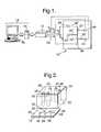
- Figure 2 shows a stage in the production of a micro-reactor that forms part of the apparatus of Figure 1;
- Figure 3 shows a two step Wittig reaction; and
- Figure 4 shows voltage and current measurements in the apparatus of Figure 1 when used to perform the Wittig reaction shown in Figure 3.
-
- As shown in Figure 1, the apparatus comprises a micro-reactor 10, a
power supply 12 and aprocessor 14. - As indicated in Figure 2, the micro-reactor 10 is formed from a
base plate 16 and anupper block 18, both of which are of glass. Thebase plate 16 has anupper surface 20 and theupper block 18 has alower surface 22. Theupper surface 20 and thelower surface 22 are bonded to one another - thesesurfaces micro-reactor 10. - The micro-reactor 10 has five interconnected channels that extend between the
base plate 16 and theupper block 18. The channels correspond to five interconnected grooves that were etched into theupper surface 20 of thebase plate 16 before thebase plate 16 and theupper block 18 were bonded together. As shown in Figure 2, before bonding of thebase plate 16 and theupper block 18, theupper surface 20 was provided with amain groove 24 having first andsecond ends main groove 24. Starting from thefirst end 26 of themain groove 24, thefirst side groove 30 extends from thefirst end 26 to a first side of themain groove 24. Thesecond side groove 32 extends to a second side of themain groove 24, and from a position approximately one quarter of the distance from thefirst end 26 to thesecond end 28 of themain groove 24. Thethird side groove 34 extends to the first side of themain groove 24, and from a position approximately mid-way between the first andsecond ends main groove 24. Thefourth side groove 36 extends to the second side of themain groove 24, and from a position approximately three quarters of the distance from thefirst end 26 to thesecond end 28 of themain groove 24. Each of the side grooves 30,32,34,36 opens into themain groove 24. - The
main groove 24 and the side grooves 30,32,34,36 were etched into theupper surface 20 in a known manner. Themain groove 24 and the fourside grooves - After bonding the
upper surface 20 of thebase plate 16 to thelower surface 22 of the upper block 18 (which is achieved using known thermal bonding techniques), thelower surface 22 closes thegrooves - The micro-reactor 10 also has first, second, third, fourth and
fifth reservoirs reservoir upper block 18 from thelower surface 22 to anupper surface 48. - The
first reservoir 38 lies above and communicates with the outer end of the first side channel 30', thesecond reservoir 40 lies above and communicates with the outer end of the second side channel 32', thethird reservoir 42 lies above and communicates with the outer end of the third side channel 34', thefourth reservoir 44 lies above and communicates with the outer end of the fourth side channel 36' and finally, thefifth reservoir 46 lies above and communicates with thesecond end 28 of the main channel 24'. - Respective platinum wire electrodes (not shown - 0.26mm in diameter) are insertable in each of the first to
fifth reservoirs - The
power supply 12 has four high voltage channels (V1 - V4 in Figure 1) which can independently supply voltages in the range of zero to ± 1,000V relative to acommon ground 50. Each of the four channels (V1 - V4) can be electrically connected to a respective one of the platinum electrodes (not shown) in the first, second, third andfourth reservoirs common ground 50 is electrically connected to the platinum electrode in thefifth reservoir 46. This is shown schematically in Figure 1. - The
power supply 12 also has four output signal channels for outputting respective signals indicative of the voltages, relative to the common ground, of the high voltage channels V1 - V4. - Additionally, the
power supply 12 is adapted for measuring currents and has four output signal channels that output respective signals indicative of currents that run, during operation, in the channels of the micro-reactor 10. For example, when the four high voltage channels V1 - V4 are connected, respectively, to the first, second, third andfourth reservoirs fifth reservoir 46, and when the channels are filled with conductive fluid, a first output signal channel indicates the current running between thefirst reservoir 38 and thefifth reservoir 46, a second output channel indicates current running between thesecond reservoir 40 and thefifth reservoir 46, a third output channel indicates current running between thethird reservoir 42 and thefifth reservoir 46, and finally, a fourth output channel indicates current running between thefourth reservoir 44 and thefifth reservoir 46. - Finally, the
power supply 12 has four input signal channels. Each one of the input channels receives signals for controlling the voltage applied by a respective one of the four high voltage channels V1 - V4. - The
power supply 12 has a setting and actual voltage accuracy of ± 0.1%. The voltage stability is 0.5% over 1 hour. Finally, the response time is 90% voltage changing within 100 µs. - The
processor 14 comprises a standard PC on which is run a programme that allows the high voltages that are applied to the first, second, third andfourth reservoirs processor 14 is also provided with twointerface boards 15 that allow theprocessor 14 to communicate with thepower supply 12. The two interface boards are available from National Instruments under the model nos. PCI-6031E and PCI-6703. - The
processor 14, together with theinterface boards 15, provide the four signals to the four input signal channels of the power supply 12 (which in turn control the high voltages applied by the voltage channels V1 - V4. The arrangement is such that the voltage of each high voltage channel V1 - V4 can be raised and lowered individually, over time, independently of the voltages of the other high voltage channels V1 - V4. - The
processor 14, via theinterface boards 15, also receives the four signals from thepower supply 12 which indicate the magnitudes of the voltages applied to the four high voltage channels V1 - V4. In this way, theprocessor 14 is able to monitor the actual voltages that are applied. - The
processor 14 also receives, via theinterface boards 15, the four signals from thepower supply 12 that indicate, respectively, the currents running between the first, second, third andfourth reservoirs fifth reservoir 46. In this way, theprocessor 14 is able to monitor the currents running in the channels of the micro-reactor 10. - The control programme is able to acquire the input data, that is to say the four input signals that relate to the voltages applied and the four input signals that indicate the currents running in the micro-reactor 10, at a rate of 10 times each second. This data is displayed and is also written to a spread sheet file for future analysis.
- The control programme is able to control the voltages applied to the micro-reactor 10, and receive the input data from the
power supply 12, automatically. - Use of the apparatus described above, to perform a chemical reaction and to monitor progress of the chemical reaction, will now be described.
- The first step is to calibrate the apparatus so as to determine the residual currents. The residual currents are the currents that are recorded by the apparatus when the
processor 14 and thepower supply 12 are set to apply voltages in the absence of any external load - that is to say when the micro-reactor 10 is not connected to thepower supply 12. This is done by recording the residual currents (in the absence of any external load) as the set voltage is increased from zero to 1,000V in 50V steps. In the apparatus described above this operation reveals a straight line calibration curve extending from 0 µA at 0V to 100 µA at 1,000V. - The results of the calibration step are stored in the
processor 14, in the form of a look-up table, so that for any voltage applied by thepower supply 12 to the micro-reactor 10 a corresponding residual current can be obtained from the look-up table. The control programme is set up so that, when a voltage is applied between any one of the first, second, third andfourth reservoirs fifth reservoir 46, the appropriate residual current, corresponding to the applied voltage, is subtracted from the apparent current running between those two reservoirs. - The apparatus can now be used to perform and monitor a chemical reaction.
- By way of example, use of the apparatus to perform and monitor a Wittig reaction will be described. The exemplary Wittig reaction is shown schematically in Figure 3. As shown in Figure 3, 2-nitrobenzyltriphenyl-phosphonium bromide was reacted with sodium methoxide to yield a coloured intermediate (ylide) plus sodium bromide. The ylide reacted with methyl 4-formylbenzoate via an oxaphosphatane intermediate to yield a mixture of cis and trans products having an alkene bond. The solvent was degassed methanol.
- A solution of 2-nitrobenzyltriphenyl-phosphonium bromide (50 µL, 0.01 M) in dry degassed methanol was added to the
first reservoir 38. Methyl 4-formylbenzoate (50 µL, 0.01 M) was premixed with sodium methoxide (0.015 M) and 50 µL of the premixed solution was introduced into thesecond reservoir 40. Dry degassed methanol was introduced into thefifth reservoir 46. Platinum electrodes were inserted into the liquids in the first, second andfifth reservoirs fourth reservoirs 42,44). - The
processor 14 was programmed so that thepower supply 12 applied a voltage of + 700V to thefirst reservoir 38 and a voltage of 650V to thesecond reservoir 40, relative to thefifth reservoir 46 which was connected to thecommon ground 50. - The applied voltages caused the 2-nitrobenzyltriphenyl-phosphonium bromide to move from the
first reservoir 38 along the first side channel 30' to the main channel 24', along the main channel 24' to thefifth reservoir 46. Additionally, the methyl 4-formylbenzoate and the sodium methoxide were moved, by the voltages, from thesecond reservoir 40 along the second side channel 32' to the main channel 24', and along the main channel 24' to thefifth reservoir 46. The reagents met and reacted, as shown in Figure 3, in the main channel 24'. The movement of the reagents was caused by movement of the liquids by electroosmotic forces. - During the course of the reaction, the apparatus was used to monitor the currents running between the
first reservoir 38 and thefifth reservoir 46, and also between thesecond reservoir 40 and thefifth reservoir 46. The voltages applied to the first andsecond reservoirs fifth reservoir 46, are shown, over time, in Figure 4. In Figure 4, theline 52 shows the current running between thefirst reservoir 38 and thefifth reservoir 46, and theline 54 shows the current running between thesecond reservoir 40 and thefifth reservoir 46. Figure 4 shows that the currents increased (while the voltages remained constant) within a time period of 40 seconds after the voltages were first applied. - The increase in the measured currents corresponds to the production of sodium bromide in the reaction, as shown in Figure 3. The sodium bromide produced ionises and this increases the conductivity of the solutions in the channels of the micro-reactor 10. Accordingly, as the voltages applied remain constant, the currents increase. Hence, the results indicate that the first stage in the reaction, the reaction of 2-nitrobenzyltriphenyl-phosphonium bromide with sodium methoxide to give the ylide and sodium bromide, was complete after 40 seconds.
- It will be appreciated that the method described above may be modified in very many ways.
- Firstly, the method is amenable to monitor any reaction in which the conductivity of the reaction mixture increases or decreases.
- Additionally, the method is not limited to use of a micro-reactor having the channel geometry described above. Micro-reactors having any channel geometry may be used - the channel geometry being chosen in view of the chemical reaction desired to be performed. Indeed, the method is not limited to the performance and monitoring of chemical reactions in micro-reactors. Reactions may be performed and currents measured in any suitable apparatus. Where micro-reactors are used, the channels preferably have maximum cross-sectional dimensions in the
range 10 µm to 500 µm. - Clearly, increases and decreases in currents that are measured will be interpreted according to the nature of the reaction that is being performed.
- Wherein the exemplary method described above monitors a reaction that occurs in a liquid, the method may also be used to monitor reactions in conductive gases.
- Monitoring may also be performed while reagents and/or products move due to electrophoresis.
- In the example described above, the voltages applied caused movement of the reagents and this controlled the reaction, by controlling mixing. Although it is preferable for the voltages to control reaction by movement of the reagents movement is not essential.
- It is preferred, as for the reaction described above, that the reaction is not thermodynamically dependent on the current.
Claims (17)
- A method of monitoring a chemical reaction comprising, performing a chemical reaction in a fluid, the reaction altering the conductivity of the fluid, applying a voltage so as to generate a current in the fluid, measuring the current, and using the current measurement to monitor the reaction.
- A method according to claim 1, wherein the reaction involves a chemical, the fluid being a liquid, the voltage causing electrokinetic movement of the chemical.
- A method according to claim 2, wherein said electrokinetic movement of the chemical comprises electroosmotic movement of the liquid.
- A method according to claim 2, wherein said electrokinetic movement of the chemical comprises electrophoretic movement of the chemical.
- A method according to any one of claims 2 to 4, wherein said electrokinetic movement controls the reaction.
- A method according to claim 5, wherein the chemical is a reagent in the reaction and said electrokinetic movement brings together the reagent with another reagent.
- A method according to any preceding claim, wherein the reaction is thermodynamically independent of the current.
- A method according to any preceding claim, wherein the reaction is performed in one or more channels in an apparatus, the apparatus having a first member with one or more grooves and a second member with a surface, the surface closing the one or more grooves to form the one or more channels.
- A method according to claim 8, wherein the or each channel has a maximum cross-sectional dimension in the range of 10 µm to 500 µm.
- A method according to any one of claims 1 to 7, wherein the reaction is performed in one or more channels, the or each channel having a maximum cross-sectional dimension in the range of 10 µm to 500 µm.
- A method according to any one of claims 8 to 10, when dependent on any one of claims 2 to 4, wherein said movement is movement along said one or more channels.
- A method according to any preceding claim, wherein the reaction involves the generation or removal of an ionised chemical causing or contributing to said altering the conductivity of the fluid.
- A method according to any preceding claim, wherein the voltage applied is varied under the control of a processor.
- A method according to claim 13, wherein the processor varies the voltage dependent on the current measurement.
- An apparatus for monitoring a chemical reaction, the apparatus comprising a device having at least one channel for performing a chemical reaction in a fluid therein, a power source for applying a voltage to fluid in the at least one channel, and means for measuring a current passing through the fluid in the channel.
- An apparatus according to claim 15, wherein the device comprises a first member having at least one groove and a second member having a surface, the surface closing the at least one groove to form said at least one channel.
- An apparatus according to claim 15 or claim 16, wherein the or each channel has a maximum cross-sectional dimension in the range of 10 µm to 500 µm.
Applications Claiming Priority (2)
| Application Number | Priority Date | Filing Date | Title |
|---|---|---|---|
| GB0119798 | 2001-08-10 | ||
| GB0119798A GB2379018B (en) | 2001-08-10 | 2001-08-10 | Monitoring of chemical reactions |
Publications (3)
| Publication Number | Publication Date |
|---|---|
| EP1283071A2 true EP1283071A2 (en) | 2003-02-12 |
| EP1283071A3 EP1283071A3 (en) | 2004-06-16 |
| EP1283071B1 EP1283071B1 (en) | 2011-11-16 |
Family
ID=9920366
Family Applications (1)
| Application Number | Title | Priority Date | Filing Date |
|---|---|---|---|
| EP02254629A Expired - Lifetime EP1283071B1 (en) | 2001-08-10 | 2002-07-02 | Monitoring of chemical reactions in channels of a micro-reactor |
Country Status (4)
| Country | Link |
|---|---|
| US (1) | US6989090B2 (en) |
| EP (1) | EP1283071B1 (en) |
| AT (1) | ATE534030T1 (en) |
| GB (1) | GB2379018B (en) |
Cited By (3)
| Publication number | Priority date | Publication date | Assignee | Title |
|---|---|---|---|---|
| EP1336432A2 (en) * | 2002-02-15 | 2003-08-20 | Syrris Limited | A microreactor |
| EP1336431A2 (en) * | 2002-02-15 | 2003-08-20 | Syrris Limited | A microreactor |
| WO2003095086A2 (en) * | 2002-05-11 | 2003-11-20 | The University Of Durham | Fluid reactor |
Families Citing this family (1)
| Publication number | Priority date | Publication date | Assignee | Title |
|---|---|---|---|---|
| GB2392920B (en) * | 2002-09-12 | 2006-03-08 | Univ Hull | Method of reacting carboxylic acids |
Family Cites Families (22)
| Publication number | Priority date | Publication date | Assignee | Title |
|---|---|---|---|---|
| US2525754A (en) * | 1948-09-29 | 1950-10-17 | Hall Lab Inc | Conductivity cell |
| US3912613A (en) * | 1973-09-17 | 1975-10-14 | Rudolph L Heuser | Two-electrode gas analysis system for electrically sensing and controlling redox reactions |
| US5149787A (en) * | 1984-05-22 | 1992-09-22 | The Blood Center Research Foundation | Method for maintaining intact, non-degraded factor VIII/von-Willebrand factor during blood processing |
| JPS6190047A (en) * | 1984-10-09 | 1986-05-08 | Taro Momo | Method for automatic measurement of biochemical reaction |
| US4794089A (en) * | 1986-03-25 | 1988-12-27 | Midwest Research Microscopy, Inc. | Method for electronic detection of a binding reaction |
| GB8619627D0 (en) * | 1986-08-12 | 1986-09-24 | Genetics Int Inc | Electrochemical assay |
| WO1990011291A1 (en) * | 1989-03-21 | 1990-10-04 | Biotech Instruments Limited | Monitoring reactions in solid-phase peptide synthesis by conductivity measurements |
| CA2079005A1 (en) * | 1990-04-11 | 1991-10-12 | Geoffrey Stephen Begg | Methods and apparatus allowing sequential chemical reactions |
| GB2244135B (en) * | 1990-05-04 | 1994-07-13 | Gen Electric Co Plc | Sensor devices |
| US5298139A (en) * | 1990-09-10 | 1994-03-29 | Board Of Trustees Of The Leland Stanford Junior University | End-column conductivity detector for capillary zone electrophoresis |
| US5262127A (en) * | 1992-02-12 | 1993-11-16 | The Regents Of The University Of Michigan | Solid state chemical micro-reservoirs |
| US5637469A (en) * | 1992-05-01 | 1997-06-10 | Trustees Of The University Of Pennsylvania | Methods and apparatus for the detection of an analyte utilizing mesoscale flow systems |
| JPH06265447A (en) * | 1993-03-16 | 1994-09-22 | Hitachi Ltd | Trace quantity reactor and trace element measuring instrument therewith |
| US5942443A (en) * | 1996-06-28 | 1999-08-24 | Caliper Technologies Corporation | High throughput screening assay systems in microscale fluidic devices |
| US5889200A (en) * | 1996-08-30 | 1999-03-30 | The University Of Dayton | Tandem technique for fluid monitoring |
| US6001231A (en) * | 1997-07-15 | 1999-12-14 | Caliper Technologies Corp. | Methods and systems for monitoring and controlling fluid flow rates in microfluidic systems |
| US5965410A (en) * | 1997-09-02 | 1999-10-12 | Caliper Technologies Corp. | Electrical current for controlling fluid parameters in microchannels |
| US6174675B1 (en) * | 1997-11-25 | 2001-01-16 | Caliper Technologies Corp. | Electrical current for controlling fluid parameters in microchannels |
| US6149787A (en) * | 1998-10-14 | 2000-11-21 | Caliper Technologies Corp. | External material accession systems and methods |
| US6361671B1 (en) * | 1999-01-11 | 2002-03-26 | The Regents Of The University Of California | Microfabricated capillary electrophoresis chip and method for simultaneously detecting multiple redox labels |
| US20020072054A1 (en) * | 2000-12-13 | 2002-06-13 | The Regents Of The University Of California | Sensor using impedance change to detect the end-point for PCR DNA amplification |
| US6729352B2 (en) * | 2001-06-07 | 2004-05-04 | Nanostream, Inc. | Microfluidic synthesis devices and methods |
-
2001
- 2001-08-10 GB GB0119798A patent/GB2379018B/en not_active Expired - Fee Related
-
2002
- 2002-07-02 EP EP02254629A patent/EP1283071B1/en not_active Expired - Lifetime
- 2002-07-02 AT AT02254629T patent/ATE534030T1/en active
- 2002-08-02 US US10/210,868 patent/US6989090B2/en not_active Expired - Lifetime
Non-Patent Citations (1)
| Title |
|---|
| None |
Cited By (10)
| Publication number | Priority date | Publication date | Assignee | Title |
|---|---|---|---|---|
| EP1336432A2 (en) * | 2002-02-15 | 2003-08-20 | Syrris Limited | A microreactor |
| EP1336431A2 (en) * | 2002-02-15 | 2003-08-20 | Syrris Limited | A microreactor |
| EP1336432A3 (en) * | 2002-02-15 | 2006-01-11 | Syrris Limited | A microreactor |
| EP1336431A3 (en) * | 2002-02-15 | 2006-01-18 | Syrris Limited | A microreactor |
| WO2003095086A2 (en) * | 2002-05-11 | 2003-11-20 | The University Of Durham | Fluid reactor |
| WO2003095086A3 (en) * | 2002-05-11 | 2004-01-08 | Univ Durham | Fluid reactor |
| GB2403919A (en) * | 2002-05-11 | 2005-01-19 | Univ Durham | Fluid reactor |
| JP2005525229A (en) * | 2002-05-11 | 2005-08-25 | ユニヴァーシティ・オヴ・ダーラム | Fluid reactor |
| GB2403919B (en) * | 2002-05-11 | 2006-09-06 | Univ Durham | Fluid reactor |
| US7541008B2 (en) | 2002-05-11 | 2009-06-02 | University Of Durham Of University Office | Fluid reactor |
Also Published As
| Publication number | Publication date |
|---|---|
| EP1283071B1 (en) | 2011-11-16 |
| EP1283071A3 (en) | 2004-06-16 |
| ATE534030T1 (en) | 2011-12-15 |
| GB2379018A (en) | 2003-02-26 |
| GB0119798D0 (en) | 2001-10-10 |
| US20030047454A1 (en) | 2003-03-13 |
| US6989090B2 (en) | 2006-01-24 |
| GB2379018B (en) | 2006-02-22 |
Similar Documents
| Publication | Publication Date | Title |
|---|---|---|
| EP0816837B1 (en) | Variable control of electroosmotic and/or electrophoretic forces within a fluid-containing structure via electrical forces | |
| Hashimoto et al. | Microchip capillary electrophoresis using on-line chemiluminescence detection | |
| ES2162643T3 (en) | PROCEDURE AND APPLIANCE TO REDUCE POLARIZATION IN AMPEROMETRIC SENSORS. | |
| Ge et al. | Electrophoretic separation in a microfluidic paper-based analytical device with an on-column wireless electrogenerated chemiluminescence detector | |
| Backofen et al. | A chip-based electrophoresis system with electrochemical detection and hydrodynamic injection | |
| Osbourn et al. | On-column electrochemical detection for microchip capillary electrophoresis | |
| Mao et al. | Dynamics of capillary isoelectric focusing in the absence of fluid flow: High-resolution computer simulation and experimental validation with whole column optical imaging | |
| Wang et al. | Capillary electrophoresis–electrochemistry microfluidic system for the determination of organic peroxides | |
| US7988839B2 (en) | Capillary electrophoresis systems and methods | |
| Wang et al. | Capillary Electrophoresis Chips with Thick‐Film Amperometric Detectors: Separation and Detection of Hydrazine Compounds | |
| JP2013502574A (en) | Proton concentration topography and method and device for producing the same | |
| EP1283071B1 (en) | Monitoring of chemical reactions in channels of a micro-reactor | |
| Wang et al. | Microchip capillary electrophoresis with electrochemical detector for fast measurements of aromatic amino acids | |
| Gabriel et al. | Hydrodynamic injection on electrophoresis microchips using an electronic micropipette | |
| Sueyoshi et al. | Application of a partial filling technique to electrophoretic analysis on microchip with T-cross channel configuration | |
| KR100596953B1 (en) | Device and method for variable control of electroosmotic or electrophoretic forces within a fluid-containing structure via electrical forces | |
| MXPA99000036A (en) | Variable control of the electroosmotic and / or electroforetic forces inside a quecony structure flush via electricity forces | |
| JP6361358B2 (en) | Electrophoresis device | |
| Dorairaj | Dual capillary electrophoresis device with electrochemical detection on a single platform | |
| Selvaganapathy | Microfabricated components for an integrated microfluidic electroanalysis system | |
| Brooks et al. | A microfabricated flow-through cell with parallel-opposed electrodes for recycling amperometric detection | |
| Dorairaj et al. | Dual capillary electrophoresis devices with electrochemical detection on a single platform | |
| CA2416606A1 (en) | Apparatus and method for reduction of bias in amperometric sensors |
Legal Events
| Date | Code | Title | Description |
|---|---|---|---|
| PUAI | Public reference made under article 153(3) epc to a published international application that has entered the european phase |
Free format text: ORIGINAL CODE: 0009012 |
|
| AK | Designated contracting states |
Designated state(s): AT BE BG CH CY CZ DE DK EE ES FI FR GB GR IE IT LI LU MC NL PT SE SK TR |
|
| AX | Request for extension of the european patent |
Extension state: AL LT LV MK RO SI |
|
| PUAL | Search report despatched |
Free format text: ORIGINAL CODE: 0009013 |
|
| AK | Designated contracting states |
Kind code of ref document: A3 Designated state(s): AT BE BG CH CY CZ DE DK EE ES FI FR GB GR IE IT LI LU MC NL PT SE SK TR |
|
| AX | Request for extension of the european patent |
Extension state: AL LT LV MK RO SI |
|
| RIC1 | Information provided on ipc code assigned before grant |
Ipc: 7G 01N 27/06 A Ipc: 7B 01J 19/00 B |
|
| 17P | Request for examination filed |
Effective date: 20041216 |
|
| AKX | Designation fees paid |
Designated state(s): AT BE BG CH CY CZ DE DK EE ES FI FR GB GR IE IT LI LU MC NL PT SE SK TR |
|
| RAP1 | Party data changed (applicant data changed or rights of an application transferred) |
Owner name: THE UNIVERSITY OF HULL |
|
| 17Q | First examination report despatched |
Effective date: 20091104 |
|
| GRAP | Despatch of communication of intention to grant a patent |
Free format text: ORIGINAL CODE: EPIDOSNIGR1 |
|
| RBV | Designated contracting states (corrected) |
Designated state(s): AT BE BG CH CY CZ DE DK EE ES FI FR GR IE IT LI LU MC NL PT SE SK TR |
|
| GRAS | Grant fee paid |
Free format text: ORIGINAL CODE: EPIDOSNIGR3 |
|
| GRAA | (expected) grant |
Free format text: ORIGINAL CODE: 0009210 |
|
| AK | Designated contracting states |
Kind code of ref document: B1 Designated state(s): AT BE BG CH CY CZ DE DK EE ES FI FR GR IE IT LI LU MC NL PT SE SK TR |
|
| REG | Reference to a national code |
Ref country code: CH Ref legal event code: EP |
|
| REG | Reference to a national code |
Ref country code: IE Ref legal event code: FG4D |
|
| REG | Reference to a national code |
Ref country code: DE Ref legal event code: R096 Ref document number: 60241553 Country of ref document: DE Effective date: 20120105 |
|
| REG | Reference to a national code |
Ref country code: NL Ref legal event code: VDEP Effective date: 20111116 |
|
| PG25 | Lapsed in a contracting state [announced via postgrant information from national office to epo] |
Ref country code: BE Free format text: LAPSE BECAUSE OF FAILURE TO SUBMIT A TRANSLATION OF THE DESCRIPTION OR TO PAY THE FEE WITHIN THE PRESCRIBED TIME-LIMIT Effective date: 20111116 Ref country code: GR Free format text: LAPSE BECAUSE OF FAILURE TO SUBMIT A TRANSLATION OF THE DESCRIPTION OR TO PAY THE FEE WITHIN THE PRESCRIBED TIME-LIMIT Effective date: 20120217 Ref country code: SE Free format text: LAPSE BECAUSE OF FAILURE TO SUBMIT A TRANSLATION OF THE DESCRIPTION OR TO PAY THE FEE WITHIN THE PRESCRIBED TIME-LIMIT Effective date: 20111116 Ref country code: NL Free format text: LAPSE BECAUSE OF FAILURE TO SUBMIT A TRANSLATION OF THE DESCRIPTION OR TO PAY THE FEE WITHIN THE PRESCRIBED TIME-LIMIT Effective date: 20111116 Ref country code: PT Free format text: LAPSE BECAUSE OF FAILURE TO SUBMIT A TRANSLATION OF THE DESCRIPTION OR TO PAY THE FEE WITHIN THE PRESCRIBED TIME-LIMIT Effective date: 20120316 |
|
| PG25 | Lapsed in a contracting state [announced via postgrant information from national office to epo] |
Ref country code: CY Free format text: LAPSE BECAUSE OF FAILURE TO SUBMIT A TRANSLATION OF THE DESCRIPTION OR TO PAY THE FEE WITHIN THE PRESCRIBED TIME-LIMIT Effective date: 20111116 |
|
| PG25 | Lapsed in a contracting state [announced via postgrant information from national office to epo] |
Ref country code: CZ Free format text: LAPSE BECAUSE OF FAILURE TO SUBMIT A TRANSLATION OF THE DESCRIPTION OR TO PAY THE FEE WITHIN THE PRESCRIBED TIME-LIMIT Effective date: 20111116 Ref country code: EE Free format text: LAPSE BECAUSE OF FAILURE TO SUBMIT A TRANSLATION OF THE DESCRIPTION OR TO PAY THE FEE WITHIN THE PRESCRIBED TIME-LIMIT Effective date: 20111116 Ref country code: DK Free format text: LAPSE BECAUSE OF FAILURE TO SUBMIT A TRANSLATION OF THE DESCRIPTION OR TO PAY THE FEE WITHIN THE PRESCRIBED TIME-LIMIT Effective date: 20111116 Ref country code: SK Free format text: LAPSE BECAUSE OF FAILURE TO SUBMIT A TRANSLATION OF THE DESCRIPTION OR TO PAY THE FEE WITHIN THE PRESCRIBED TIME-LIMIT Effective date: 20111116 Ref country code: BG Free format text: LAPSE BECAUSE OF FAILURE TO SUBMIT A TRANSLATION OF THE DESCRIPTION OR TO PAY THE FEE WITHIN THE PRESCRIBED TIME-LIMIT Effective date: 20120216 |
|
| PG25 | Lapsed in a contracting state [announced via postgrant information from national office to epo] |
Ref country code: IT Free format text: LAPSE BECAUSE OF FAILURE TO SUBMIT A TRANSLATION OF THE DESCRIPTION OR TO PAY THE FEE WITHIN THE PRESCRIBED TIME-LIMIT Effective date: 20111116 |
|
| REG | Reference to a national code |
Ref country code: AT Ref legal event code: MK05 Ref document number: 534030 Country of ref document: AT Kind code of ref document: T Effective date: 20111116 |
|
| PLBE | No opposition filed within time limit |
Free format text: ORIGINAL CODE: 0009261 |
|
| STAA | Information on the status of an ep patent application or granted ep patent |
Free format text: STATUS: NO OPPOSITION FILED WITHIN TIME LIMIT |
|
| 26N | No opposition filed |
Effective date: 20120817 |
|
| REG | Reference to a national code |
Ref country code: DE Ref legal event code: R097 Ref document number: 60241553 Country of ref document: DE Effective date: 20120817 |
|
| PG25 | Lapsed in a contracting state [announced via postgrant information from national office to epo] |
Ref country code: AT Free format text: LAPSE BECAUSE OF FAILURE TO SUBMIT A TRANSLATION OF THE DESCRIPTION OR TO PAY THE FEE WITHIN THE PRESCRIBED TIME-LIMIT Effective date: 20111116 |
|
| PG25 | Lapsed in a contracting state [announced via postgrant information from national office to epo] |
Ref country code: MC Free format text: LAPSE BECAUSE OF NON-PAYMENT OF DUE FEES Effective date: 20120731 |
|
| REG | Reference to a national code |
Ref country code: CH Ref legal event code: PL |
|
| PG25 | Lapsed in a contracting state [announced via postgrant information from national office to epo] |
Ref country code: ES Free format text: LAPSE BECAUSE OF FAILURE TO SUBMIT A TRANSLATION OF THE DESCRIPTION OR TO PAY THE FEE WITHIN THE PRESCRIBED TIME-LIMIT Effective date: 20120227 Ref country code: CH Free format text: LAPSE BECAUSE OF NON-PAYMENT OF DUE FEES Effective date: 20120731 Ref country code: LI Free format text: LAPSE BECAUSE OF NON-PAYMENT OF DUE FEES Effective date: 20120731 |
|
| REG | Reference to a national code |
Ref country code: IE Ref legal event code: MM4A |
|
| PG25 | Lapsed in a contracting state [announced via postgrant information from national office to epo] |
Ref country code: FI Free format text: LAPSE BECAUSE OF FAILURE TO SUBMIT A TRANSLATION OF THE DESCRIPTION OR TO PAY THE FEE WITHIN THE PRESCRIBED TIME-LIMIT Effective date: 20111116 |
|
| PG25 | Lapsed in a contracting state [announced via postgrant information from national office to epo] |
Ref country code: IE Free format text: LAPSE BECAUSE OF NON-PAYMENT OF DUE FEES Effective date: 20120702 |
|
| PG25 | Lapsed in a contracting state [announced via postgrant information from national office to epo] |
Ref country code: TR Free format text: LAPSE BECAUSE OF FAILURE TO SUBMIT A TRANSLATION OF THE DESCRIPTION OR TO PAY THE FEE WITHIN THE PRESCRIBED TIME-LIMIT Effective date: 20111116 |
|
| PG25 | Lapsed in a contracting state [announced via postgrant information from national office to epo] |
Ref country code: LU Free format text: LAPSE BECAUSE OF NON-PAYMENT OF DUE FEES Effective date: 20120702 |
|
| REG | Reference to a national code |
Ref country code: FR Ref legal event code: PLFP Year of fee payment: 15 |
|
| REG | Reference to a national code |
Ref country code: FR Ref legal event code: PLFP Year of fee payment: 16 |
|
| REG | Reference to a national code |
Ref country code: FR Ref legal event code: PLFP Year of fee payment: 17 |
|
| PGFP | Annual fee paid to national office [announced via postgrant information from national office to epo] |
Ref country code: FR Payment date: 20180726 Year of fee payment: 17 Ref country code: DE Payment date: 20180727 Year of fee payment: 17 |
|
| REG | Reference to a national code |
Ref country code: DE Ref legal event code: R119 Ref document number: 60241553 Country of ref document: DE |
|
| PG25 | Lapsed in a contracting state [announced via postgrant information from national office to epo] |
Ref country code: DE Free format text: LAPSE BECAUSE OF NON-PAYMENT OF DUE FEES Effective date: 20200201 |
|
| PG25 | Lapsed in a contracting state [announced via postgrant information from national office to epo] |
Ref country code: FR Free format text: LAPSE BECAUSE OF NON-PAYMENT OF DUE FEES Effective date: 20190731 |