EP1282140A1 - Magnetkern, insbesondere für einen Transformator oder eine Drossel, sowie Verfahren zum Herstellen eines Magnetkerns - Google Patents
Magnetkern, insbesondere für einen Transformator oder eine Drossel, sowie Verfahren zum Herstellen eines Magnetkerns Download PDFInfo
- Publication number
- EP1282140A1 EP1282140A1 EP01118228A EP01118228A EP1282140A1 EP 1282140 A1 EP1282140 A1 EP 1282140A1 EP 01118228 A EP01118228 A EP 01118228A EP 01118228 A EP01118228 A EP 01118228A EP 1282140 A1 EP1282140 A1 EP 1282140A1
- Authority
- EP
- European Patent Office
- Prior art keywords
- magnetic core
- stack
- connecting device
- weld seam
- base plate
- Prior art date
- Legal status (The legal status is an assumption and is not a legal conclusion. Google has not performed a legal analysis and makes no representation as to the accuracy of the status listed.)
- Granted
Links
- 238000004519 manufacturing process Methods 0.000 title claims abstract description 6
- 238000000034 method Methods 0.000 title claims description 7
- 238000003466 welding Methods 0.000 claims description 27
- 238000005452 bending Methods 0.000 claims description 2
- 239000004020 conductor Substances 0.000 claims description 2
- 230000000284 resting effect Effects 0.000 claims description 2
- 239000002184 metal Substances 0.000 claims 1
- 239000011241 protective layer Substances 0.000 description 4
- XEEYBQQBJWHFJM-UHFFFAOYSA-N Iron Chemical compound [Fe] XEEYBQQBJWHFJM-UHFFFAOYSA-N 0.000 description 2
- 238000007598 dipping method Methods 0.000 description 2
- 229910000831 Steel Inorganic materials 0.000 description 1
- 230000001419 dependent effect Effects 0.000 description 1
- 230000009189 diving Effects 0.000 description 1
- 238000005553 drilling Methods 0.000 description 1
- 230000005674 electromagnetic induction Effects 0.000 description 1
- 238000009434 installation Methods 0.000 description 1
- 229910052742 iron Inorganic materials 0.000 description 1
- 239000010410 layer Substances 0.000 description 1
- 238000003892 spreading Methods 0.000 description 1
- 239000010959 steel Substances 0.000 description 1
Images

Classifications
-
- H—ELECTRICITY
- H01—ELECTRIC ELEMENTS
- H01F—MAGNETS; INDUCTANCES; TRANSFORMERS; SELECTION OF MATERIALS FOR THEIR MAGNETIC PROPERTIES
- H01F27/00—Details of transformers or inductances, in general
- H01F27/24—Magnetic cores
- H01F27/245—Magnetic cores made from sheets, e.g. grain-oriented
-
- H—ELECTRICITY
- H01—ELECTRIC ELEMENTS
- H01F—MAGNETS; INDUCTANCES; TRANSFORMERS; SELECTION OF MATERIALS FOR THEIR MAGNETIC PROPERTIES
- H01F27/00—Details of transformers or inductances, in general
- H01F27/24—Magnetic cores
- H01F27/26—Fastening parts of the core together; Fastening or mounting the core on casing or support
- H01F27/263—Fastening parts of the core together
-
- H—ELECTRICITY
- H01—ELECTRIC ELEMENTS
- H01F—MAGNETS; INDUCTANCES; TRANSFORMERS; SELECTION OF MATERIALS FOR THEIR MAGNETIC PROPERTIES
- H01F27/00—Details of transformers or inductances, in general
- H01F27/40—Structural association with built-in electric component, e.g. fuse
- H01F27/402—Association of measuring or protective means
Definitions
- the present invention relates to the field of electromagnetic Components. It relates to a magnetic core according to the preamble of the claim 1 and a method for producing such a magnetic core. On such a magnetic core is e.g. B. from the document DE-C2-37 37 887 known.
- Magnetic cores for components based on electromagnetic induction such as z. B. transformers or chokes usually consist of a package of stacked iron sheets that reduce eddy current losses are isolated from each other.
- the laminated core usually shows in at the corners Through holes for screw bolts to be screwed of the laminated core and, if necessary, for attaching foot angles or other assembly aids.
- connection device can be provided that allows the end to connect a ground connection in an electrically conductive manner to the magnetic core.
- Out Screw terminals which are screwed to the magnetic core are known in practice can be. The same bolts can be used for screwing, which are also used to screw the stack of sheets together.
- connection device subsequent installation of such a connection device is complex. At the same time, it is difficult to make the necessary good electrical contact between the connection device and the core of the magnetic core and ensure permanently. This applies in particular to the case that the magnetic core is covered with an insulating protective layer by dipping carefully in the area of the connection device must be removed.
- the object is achieved by the entirety of the features of claims 1 and 12 solved.
- the essence of the invention is in a magnetic core with a the connection device by means of a welded welded laminated core to be firmly attached to the magnetic core by means of the same weld seam and to be electrically connected to the magnetic core. This is without procedural Safe and electrically perfect connection the connection device to all sheets of the magnetic core stack.
- connection device comprises a base plate resting on the top or bottom of the stack, from which a welding tab is bent at right angles, such that the welding tab runs with a welding edge in the welding seam.
- a such connection device can be easily as a stamped and bent part produce and enables easy attachment of the device to the magnetic core.
- the connecting device means for positioning the Includes connection device on the magnetic core preferably the magnetic core has a recess on the top or bottom of the stack, and the positioning means comprise a pin projecting at right angles from the base plate, which engages in the recess, and in particular the pin formed by a plate section bent at right angles from the base plate becomes.
- the recess is preferably one in the stacking direction through the Stacking hole in question.
- connection device Means for clamping an electrical conductor, wherein the means for clamping either one at right angles from the base plate outside clamp plate with a threaded hole, or a resilient clamping device which is connected to the base plate.
- connection device when placed on the stack is positioned by positioning means so that it has a welding edge the weld seam to be formed comes to rest.
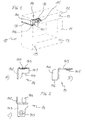
- Fig. 1 is a perspective side view of a first preferred embodiment of a magnetic core 10 according to the invention.
- the dot-dash Drawn magnetic core 10 consists of two in a manner known per se separate laminated cores, namely a lower part 11 and an upper part 12.
- Das Lower part 11 has the shape of a square U, but could also be E-shaped his.
- the upper part 12 has the shape of an I.
- the upper part 12 is on the lower part 11 set and with this on the abutting outer edges by welding seams 17 connected.
- the direction of the weld seams 17 is also the stacking direction the laminated cores (11, 12).
- the magnetic core 10 forms in the welded form a closed magnetic circuit in which the magnetic field lines from on the magnetic core 10 seated, not shown in Fig. 1, electromagnetic Coils run.
- connection device 14 is provided on the magnetic core 10, which has the configuration shown in Figs. 2A to 2C.
- the connection device 14 is preferably a stamped and bent part, e.g. from a 1.5 to 2 mm thick steel sheet is made.
- the connection device 14 has a base plate 141, on the one side a welding tab 142 is bent at right angles.
- the welding tab 142 is bounded on one side by a welding edge 146.
- a clamping plate 143 is bent at right angles.
- a threaded hole 145 is provided, in which a screw 16 for clamping a ground connection between the clamping plate 143 and a clamping plate 15 can be screwed (see Fig. 1).
- From the base plate 141 is also a narrow, elongated plate section bent at right angles and forms a pin 144. Pin 144 points in the same direction as that Welding lug 142.
- the clamping plate 143 points into the opposite one Direction.
- connection device 14 To attach the connection device 14 to the magnetic core 10, first of all the laminated core of the upper part 12 is placed on the laminated core of the lower part 12 and the connection device 14 - as shown in FIG. 1 - with the base plate 141 placed on the top of the (upper) laminated core (upper part 12) so that the angled welding tab 142 rests on the side of the laminated core, wherein the welding edge 146 on the parting line between the upper part 12 and the Lower part 11 comes to rest. The exact superimposition of the welding edge 146 and the parting line is ensured by the connection device 14 engages in this position with the pin 144 in one of the bores 13, which are arranged at the corners of the magnetic core 10.
- the welding tab 142 at the welding edge is simultaneously 146 included in the welding and the connection device 14 so cohesively connected to the magnetic core 10.
- the weld can be done, for example, using the TIG method.
- this protective layer also covers the inside of the Threaded hole 145. So when connecting a ground connection later the screw 16 still has good electrical contact with the clamping plate 143 produces, it is advantageous if the screw 16 is designed so that it the thread covered by the protective layer cuts free in the threaded hole 145.
- connection device 18 used in this example also has a base plate 181, of which a welding tab 182 a welding edge 186, a pin 184 and a clamping plate 183 with a Threaded hole 185 are bent at right angles.
- the parts listed have in essentially the same function as in the embodiment of FIG. 1, with the difference that the welding tab 182 is now below the weld seam 17 lies and the clamping plate 183 on the lower side of the connection device 18 is arranged.
- the threaded hole 185 must be inserted after the Magnetic core 10 are cut free.
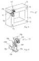
- the connecting device 19 shown in Fig. 5 individually reproduced, consists essentially of two parts:
- the first part comprises similar to the connection device 18 of FIG. 3A, a base plate 191, of one a welding tab 192 with a welding edge 198 and a pin 194 and a connecting plate 193 with a hole are bent at right angles.
- the second part is designed as a resilient clamping device in which a spring clip 197 is guided by a yoke 196 formed on a stamped and bent part.
- the Stamping-bending part with the spring clip 197 is with a nose in the hole in the Connection plate 193 inserted and by means of an attached to the base plate 191, spread locking element 195 latched against the base plate 191.
- the spreading of the locking element 195 ensures that when locking the resilient clamping device 196, 197 after immersing the magnetic core 10 scraped off an insulating layer deposited during dipping from the locking element 195 and so a good electrical contact is made.
- the springy Clamping device 196, 197 can directly lead to a ground connection without a screw be clamped while making contact.
Landscapes
- Engineering & Computer Science (AREA)
- Power Engineering (AREA)
- Coils Or Transformers For Communication (AREA)
- Manufacturing Cores, Coils, And Magnets (AREA)
Abstract
Description
- Fig. 1
- in einer perspektivischen Seitenansicht ein erstes bevorzugtes Ausführungsbeispiel eines Magnetkerns (strichpunktiert) mit Anschlussvorrichtung nach der Erfindung;
- Fig. 2
- in mehreren Teilansichten (A) bis (C) die Anschlussvorrichtung aus Fig. 1 für sich genommen;
- Fig. 3
- in einer Teilfigur (B) ein zu Fig. 1 vergleichbares anderes Ausführungsbeispiel der Erfindung; eine weitere Teilfigur (A) zeigt die Anschlussvorrichtung für sich genommen;
- Fig. 4
- ein weiteres bevorzugtes Ausführungsbeispiel der Erfindung mit einer Anschlussvorrichtung in Form einer federnden (schraubenlosen) Klemmeinrichtung; und
- Fig. 5
- für sich genommen die Anschlussvorrichtung aus Fig. 4.
- 10
- Magnetkern
- 11
- Unterteil
- 12
- Oberteil
- 13
- Bohrung
- 14
- Anschlussvorrichtung
- 15
- Klemmblech
- 16
- Schraube
- 17
- Schweißnaht
- 18
- Anschlussvorrichtung
- 19
- Anschlussvorrichtung
- 141,181,191
- Grundplatte
- 142,182,192
- Schweisslasche
- 143,183
- Klemmplatte
- 144,184,194
- Stift
- 145,185
- Gewindeloch
- 146,186,198
- Anschweisskante
- 193
- Anschlussplatte
- 195
- Rastelement
- 196
- Joch
- 197
- Federbügel
Claims (13)
- Magnetkern (10), insbesondere für einen Transformator oder eine Drossel, welcher Magnetkern (10) aus wenigstens einem Stapel von Kernblechen besteht, die durch wenigstens eine in Stapelrichtung an der Außenseite des Stapels verlaufende Schweissnaht (17) untereinander verbunden sind, und welcher Magnetkern (10) eine Anschlussvorrichtung (14, 18, 19) zum Verbinden des Magnetkerns (10) mit Masse aufweist, dadurch gekennzeichnet, dass die Anschlussvorrichtung (14, 18, 19) mittels der Schweissnaht (17) am Magnetkern (10) stoffschlüssig befestigt und mit dem Magnetkern (10) elektrisch leitend verbunden ist.
- Magnetkern nach Anspruch 1, dadurch gekennzeichnet, dass die Anschlussvorrichtung (14, 18, 19) eine auf der Ober-oder Unterseite des Stapels aufliegende Grundplatte (141, 181, 191) umfasst, von welcher eine Schweisslasche (142, 182, 192) rechtwinklig abgebogen ist, derart, dass die Schweisslasche (142, 182, 192) mit einer Anschweisskante (146, 186, 198) in der Schweissnaht (17) verläuft.
- Magnetkern nach Anspruch 2, dadurch gekennzeichnet, dass die Anschlussvorrichtung (14, 18, 19) Mittel (144, 184, 194) zum Positionieren der Anschlussvorrichtung (14, 18, 19) am Magnetkern (10) umfasst.
- Magnetkern nach Anspruch 3, dadurch gekennzeichnet, dass der Magnetkern (10) auf der Ober-oder Unterseite des Stapels eine Ausnehmung (13) aufweist, und dass die Positioniermittel einen von der Grundplatte (141, 181, 191) rechtwinklig abstehenden Stift (144, 184, 194) umfassen, welcher in die Ausnehmung (13) eingreift.
- Magnetkern nach Anspruch 4, dadurch gekennzeichnet, dass der Stift (144, 184,194) durch einen rechtwinklig von der Grundplatte (141, 181, 191) abgebogenen Plattenabschnitt gebildet wird.
- Magnetkern nach einem der Ansprüche 4 und 5,dadurch gekennzeichnet, dass die Ausnehmung eine in Stapelrichtung durch den Stapel verlaufende Bohrung (13) ist.
- Magnetkern nach einem der Ansprüche 2 bis 6, dadurch gekennzeichnet, dass die Anschlussvorrichtung (14, 18, 19) Mittel (15, 16, 143, 145; 183, 185; 193, 195, 196, 197) zum Festklemmen eines elektrischen Leiters aufweist.
- Magnetkern nach Anspruch 7, dadurch gekennzeichnet, dass die Mittel zum Festklemmen eine von der Grundplatte (141, 181) rechtwinklig nach außen abgebogene Klemmplatte (143, 183) mit einem Gewindeloch (145,185) umfassen.
- Magnetkern nach Anspruch 7, dadurch gekennzeichnet, dass die Mittel zum Festklemmen eine federnde Klemmvorrichtung (196,197) umfassen, welche mit der Grundplatte (191) verbunden ist.
- Magnetkern nach einem der Ansprüche 1 bis 9, dadurch gekennzeichnet, dass die Anschlussvorrichtung (14, 18, 19) aus Blech durch Stanzen und Biegen hergestellt ist.
- Magnetkern nach einem der Ansprüche 1 bis 10, dadurch gekennzeichnet, dass der Magnetkern (10) aus einem U- oder E-förmigen Unterteil (11) und einem I-förmigen Oberteil (12) besteht, und dass die Schweißnaht (17) das Unterteil (11) und dass Oberteil (12) miteinander verbindet.
- Verfahren zum Herstellen eines Magnetkerns (10) nach einem der Ansprüche 1 bis 11, dadurch gekennzeichnet, dass aus den Kernblechen ein Stapel gebildet wird, dass die Anschlussvorrichtung (14, 18, 19) auf den Stapel aus Kernblechen aufgesetzt wird, und dass die Kernbleche des Stapels und die Anschlussvorrichtung (14, 18, 19) durch einen Schweissvorgang unter Bildung der Schweissnaht (17) miteinander verbunden werden.
- Verfahren nach Anspruch 12, dadurch gekennzeichnet, dass die Anschlussvorrichtung (14, 18, 19) beim Aufsetzen auf den Stapel durch Positioniermittel (144, 184, 194) so positioniert wird, dass sie mit einer Anschweisskante (146, 186, 198) in der zu bildenden Schweissnaht (17) zu liegen kommt.
Priority Applications (4)
| Application Number | Priority Date | Filing Date | Title |
|---|---|---|---|
| DE50112933T DE50112933D1 (de) | 2001-07-30 | 2001-07-30 | Magnetkern, insbesondere für einen Transformator oder eine Drossel, sowie Verfahren zum Herstellen eines Magnetkerns |
| EP01118228A EP1282140B1 (de) | 2001-07-30 | 2001-07-30 | Magnetkern, insbesondere für einen Transformator oder eine Drossel, sowie Verfahren zum Herstellen eines Magnetkerns |
| AT01118228T ATE371938T1 (de) | 2001-07-30 | 2001-07-30 | Magnetkern, insbesondere für einen transformator oder eine drossel, sowie verfahren zum herstellen eines magnetkerns |
| ES01118228T ES2290075T3 (es) | 2001-07-30 | 2001-07-30 | Nucleo magnetico, especialmente para un transformador o un inductor, y procedimiento para la produccion de un nucleo magnetico. |
Applications Claiming Priority (1)
| Application Number | Priority Date | Filing Date | Title |
|---|---|---|---|
| EP01118228A EP1282140B1 (de) | 2001-07-30 | 2001-07-30 | Magnetkern, insbesondere für einen Transformator oder eine Drossel, sowie Verfahren zum Herstellen eines Magnetkerns |
Publications (2)
| Publication Number | Publication Date |
|---|---|
| EP1282140A1 true EP1282140A1 (de) | 2003-02-05 |
| EP1282140B1 EP1282140B1 (de) | 2007-08-29 |
Family
ID=8178158
Family Applications (1)
| Application Number | Title | Priority Date | Filing Date |
|---|---|---|---|
| EP01118228A Expired - Lifetime EP1282140B1 (de) | 2001-07-30 | 2001-07-30 | Magnetkern, insbesondere für einen Transformator oder eine Drossel, sowie Verfahren zum Herstellen eines Magnetkerns |
Country Status (4)
| Country | Link |
|---|---|
| EP (1) | EP1282140B1 (de) |
| AT (1) | ATE371938T1 (de) |
| DE (1) | DE50112933D1 (de) |
| ES (1) | ES2290075T3 (de) |
Citations (3)
| Publication number | Priority date | Publication date | Assignee | Title |
|---|---|---|---|---|
| US4899122A (en) * | 1987-12-05 | 1990-02-06 | Abb Ceag Licht- Und Stromversorgungstechnik Gmbh | Transformer, choke and the like |
| US5239278A (en) * | 1991-12-09 | 1993-08-24 | Basler Electric Company | Transformer and mounting bracket assembly |
| US5926946A (en) * | 1994-12-28 | 1999-07-27 | Matsushita Electric Industrial Co., Ltd. | Method for manufacturing reactor |
-
2001
- 2001-07-30 ES ES01118228T patent/ES2290075T3/es not_active Expired - Lifetime
- 2001-07-30 DE DE50112933T patent/DE50112933D1/de not_active Expired - Lifetime
- 2001-07-30 EP EP01118228A patent/EP1282140B1/de not_active Expired - Lifetime
- 2001-07-30 AT AT01118228T patent/ATE371938T1/de not_active IP Right Cessation
Patent Citations (3)
| Publication number | Priority date | Publication date | Assignee | Title |
|---|---|---|---|---|
| US4899122A (en) * | 1987-12-05 | 1990-02-06 | Abb Ceag Licht- Und Stromversorgungstechnik Gmbh | Transformer, choke and the like |
| US5239278A (en) * | 1991-12-09 | 1993-08-24 | Basler Electric Company | Transformer and mounting bracket assembly |
| US5926946A (en) * | 1994-12-28 | 1999-07-27 | Matsushita Electric Industrial Co., Ltd. | Method for manufacturing reactor |
Also Published As
| Publication number | Publication date |
|---|---|
| ATE371938T1 (de) | 2007-09-15 |
| EP1282140B1 (de) | 2007-08-29 |
| ES2290075T3 (es) | 2008-02-16 |
| DE50112933D1 (de) | 2007-10-11 |
Similar Documents
| Publication | Publication Date | Title |
|---|---|---|
| DE69319283T2 (de) | Metallträger für ein Mehrschicht-Leitergitter und Verfahren zum Herstellen desselben | |
| DE68917694T2 (de) | Schaltungsplattenzusammenbau und Kontaktstift, der darin verwendet wird. | |
| DE19821234B4 (de) | Verfahren und Vorrichtung zum elektrischen Anschluss einer in einem Sicherungsgehäuse montierten Schmelzsicherung mit einem externen elektrischen Draht | |
| DE112009001937T5 (de) | Schichttransformator für DC/DC-Umwandler | |
| DE69016189T2 (de) | Elektrische verbinder. | |
| DE112014006848T5 (de) | Verfahren zum Verbinden eines Anschlusselements und einer elektrischen Leitung und ein Verbindungsanschlusselement für eine elektrische Leitung | |
| DE102020100364B4 (de) | Leistungselektronische Baugruppe mit einem Substrat, einer Hülse und einem Kontaktstift und Verfahren zur Herstellung einer solchen Baugruppe | |
| DE60009834T2 (de) | Verfahren für Schaltungsaufbau und Schaltungsverbindungsanordnung in elektrischem Anschlusskasten | |
| DE60004173T2 (de) | Induktives elektronisches bauteil, und herstellungsverfahren | |
| DE3706964C2 (de) | ||
| DE102016106835B3 (de) | Busbar mit einer Mehrzahl von Filmkondensatoren | |
| DE2812976C2 (de) | Verfahren zur Feststellung des Versatzes zwischen Leiterbahnen und Kontaktlöchern bei einer Leiterplatte sowie eine Leiterplatte zur Verwendung in diesem Verfahren | |
| DE102017200466B4 (de) | Induktives Bauteil und Verfahren zur Herstellung eines induktiven Bauteils | |
| DE102007020290B4 (de) | Verfahren zur Herstellung eines becherförmigen Gehäuses für ein elektrisches Bauelement und damit hergestelltes Gehäuse sowie elektrisches Bauelement mit diesem Gehäuse | |
| DE10009042A1 (de) | Bauteil aus Blech zur Doppelmuster-Leitungsverbindung und gedruckte Schaltungsplatte | |
| EP1282140B1 (de) | Magnetkern, insbesondere für einen Transformator oder eine Drossel, sowie Verfahren zum Herstellen eines Magnetkerns | |
| EP0878870A1 (de) | HF-Koaxial-Steckverbinderteil | |
| DE3510638C1 (de) | Induktives Miniatur-Bauelement, insbesondere Miniatur-Spule sowie Verfahren zur Herstellung eines solchen Bauelements | |
| DE4337054B4 (de) | Spule | |
| DE2041110A1 (de) | Befestigungsvorrichtung zum Befestigen der aeusseren Enden zweier Spiralfedern in zeithaltenden Instrumenten | |
| EP0995135A2 (de) | Transponderanordnung und verfahren zu deren herstellung | |
| EP0768815A1 (de) | Verfahren zur Herstellung elektrischer Schaltungen mit einer Leiterplatte | |
| EP1287537B1 (de) | Induktives miniaturbauelement für smd-montage, sowie verfahren zu seiner herstellung | |
| DE60201537T2 (de) | Elektrische verbindungsanordnung für elektronische bauteile | |
| EP1598839B1 (de) | Übertrager für ein Gerät der Hochfrequenztechnik, der direkt auf einer Leiterplatte angeordnet ist |
Legal Events
| Date | Code | Title | Description |
|---|---|---|---|
| PUAI | Public reference made under article 153(3) epc to a published international application that has entered the european phase |
Free format text: ORIGINAL CODE: 0009012 |
|
| AK | Designated contracting states |
Designated state(s): AT BE CH CY DE DK ES FI FR GB GR IE IT LI LU MC NL PT SE TR |
|
| AX | Request for extension of the european patent |
Extension state: AL LT LV MK RO SI |
|
| 17P | Request for examination filed |
Effective date: 20030524 |
|
| AKX | Designation fees paid |
Designated state(s): AT BE CH CY DE DK ES FI FR GB GR IE IT LI LU MC NL PT SE TR |
|
| 17Q | First examination report despatched |
Effective date: 20040204 |
|
| GRAP | Despatch of communication of intention to grant a patent |
Free format text: ORIGINAL CODE: EPIDOSNIGR1 |
|
| GRAS | Grant fee paid |
Free format text: ORIGINAL CODE: EPIDOSNIGR3 |
|
| GRAA | (expected) grant |
Free format text: ORIGINAL CODE: 0009210 |
|
| AK | Designated contracting states |
Kind code of ref document: B1 Designated state(s): AT BE CH CY DE DK ES FI FR GB GR IE IT LI LU MC NL PT SE TR |
|
| REG | Reference to a national code |
Ref country code: GB Ref legal event code: FG4D Free format text: NOT ENGLISH |
|
| REG | Reference to a national code |
Ref country code: CH Ref legal event code: EP Ref country code: CH Ref legal event code: PCAR Free format text: ISLER & PEDRAZZINI AG;POSTFACH 1772;8027 ZUERICH (CH) Ref country code: CH Ref legal event code: NV Representative=s name: ISLER & PEDRAZZINI AG |
|
| REG | Reference to a national code |
Ref country code: IE Ref legal event code: FG4D Free format text: LANGUAGE OF EP DOCUMENT: GERMAN |
|
| REF | Corresponds to: |
Ref document number: 50112933 Country of ref document: DE Date of ref document: 20071011 Kind code of ref document: P |
|
| PG25 | Lapsed in a contracting state [announced via postgrant information from national office to epo] |
Ref country code: FI Free format text: LAPSE BECAUSE OF FAILURE TO SUBMIT A TRANSLATION OF THE DESCRIPTION OR TO PAY THE FEE WITHIN THE PRESCRIBED TIME-LIMIT Effective date: 20070829 |
|
| REG | Reference to a national code |
Ref country code: ES Ref legal event code: FG2A Ref document number: 2290075 Country of ref document: ES Kind code of ref document: T3 |
|
| GBV | Gb: ep patent (uk) treated as always having been void in accordance with gb section 77(7)/1977 [no translation filed] |
Effective date: 20070829 |
|
| REG | Reference to a national code |
Ref country code: IE Ref legal event code: FD4D |
|
| EN | Fr: translation not filed | ||
| PG25 | Lapsed in a contracting state [announced via postgrant information from national office to epo] |
Ref country code: DK Free format text: LAPSE BECAUSE OF FAILURE TO SUBMIT A TRANSLATION OF THE DESCRIPTION OR TO PAY THE FEE WITHIN THE PRESCRIBED TIME-LIMIT Effective date: 20070829 Ref country code: GR Free format text: LAPSE BECAUSE OF FAILURE TO SUBMIT A TRANSLATION OF THE DESCRIPTION OR TO PAY THE FEE WITHIN THE PRESCRIBED TIME-LIMIT Effective date: 20071130 |
|
| PG25 | Lapsed in a contracting state [announced via postgrant information from national office to epo] |
Ref country code: GB Free format text: LAPSE BECAUSE OF FAILURE TO SUBMIT A TRANSLATION OF THE DESCRIPTION OR TO PAY THE FEE WITHIN THE PRESCRIBED TIME-LIMIT Effective date: 20070829 Ref country code: IE Free format text: LAPSE BECAUSE OF FAILURE TO SUBMIT A TRANSLATION OF THE DESCRIPTION OR TO PAY THE FEE WITHIN THE PRESCRIBED TIME-LIMIT Effective date: 20070829 Ref country code: PT Free format text: LAPSE BECAUSE OF FAILURE TO SUBMIT A TRANSLATION OF THE DESCRIPTION OR TO PAY THE FEE WITHIN THE PRESCRIBED TIME-LIMIT Effective date: 20080129 |
|
| PG25 | Lapsed in a contracting state [announced via postgrant information from national office to epo] |
Ref country code: SE Free format text: LAPSE BECAUSE OF FAILURE TO SUBMIT A TRANSLATION OF THE DESCRIPTION OR TO PAY THE FEE WITHIN THE PRESCRIBED TIME-LIMIT Effective date: 20071129 |
|
| PLBE | No opposition filed within time limit |
Free format text: ORIGINAL CODE: 0009261 |
|
| STAA | Information on the status of an ep patent application or granted ep patent |
Free format text: STATUS: NO OPPOSITION FILED WITHIN TIME LIMIT |
|
| PGFP | Annual fee paid to national office [announced via postgrant information from national office to epo] |
Ref country code: CH Payment date: 20080527 Year of fee payment: 8 |
|
| 26N | No opposition filed |
Effective date: 20080530 |
|
| PGFP | Annual fee paid to national office [announced via postgrant information from national office to epo] |
Ref country code: TR Payment date: 20080618 Year of fee payment: 8 Ref country code: IT Payment date: 20080619 Year of fee payment: 8 |
|
| PGFP | Annual fee paid to national office [announced via postgrant information from national office to epo] |
Ref country code: ES Payment date: 20080709 Year of fee payment: 8 |
|
| PGFP | Annual fee paid to national office [announced via postgrant information from national office to epo] |
Ref country code: NL Payment date: 20080619 Year of fee payment: 8 Ref country code: AT Payment date: 20080610 Year of fee payment: 8 |
|
| PG25 | Lapsed in a contracting state [announced via postgrant information from national office to epo] |
Ref country code: MC Free format text: LAPSE BECAUSE OF NON-PAYMENT OF DUE FEES Effective date: 20080731 |
|
| PG25 | Lapsed in a contracting state [announced via postgrant information from national office to epo] |
Ref country code: CY Free format text: LAPSE BECAUSE OF FAILURE TO SUBMIT A TRANSLATION OF THE DESCRIPTION OR TO PAY THE FEE WITHIN THE PRESCRIBED TIME-LIMIT Effective date: 20070829 |
|
| REG | Reference to a national code |
Ref country code: CH Ref legal event code: PL |
|
| NLV4 | Nl: lapsed or anulled due to non-payment of the annual fee |
Effective date: 20100201 |
|
| PG25 | Lapsed in a contracting state [announced via postgrant information from national office to epo] |
Ref country code: CH Free format text: LAPSE BECAUSE OF NON-PAYMENT OF DUE FEES Effective date: 20090731 Ref country code: LI Free format text: LAPSE BECAUSE OF NON-PAYMENT OF DUE FEES Effective date: 20090731 |
|
| PG25 | Lapsed in a contracting state [announced via postgrant information from national office to epo] |
Ref country code: AT Free format text: LAPSE BECAUSE OF NON-PAYMENT OF DUE FEES Effective date: 20090730 |
|
| PG25 | Lapsed in a contracting state [announced via postgrant information from national office to epo] |
Ref country code: LU Free format text: LAPSE BECAUSE OF NON-PAYMENT OF DUE FEES Effective date: 20080730 Ref country code: BE Free format text: LAPSE BECAUSE OF NON-PAYMENT OF DUE FEES Effective date: 20080731 |
|
| REG | Reference to a national code |
Ref country code: ES Ref legal event code: FD2A Effective date: 20090731 |
|
| PG25 | Lapsed in a contracting state [announced via postgrant information from national office to epo] |
Ref country code: ES Free format text: LAPSE BECAUSE OF NON-PAYMENT OF DUE FEES Effective date: 20090731 |
|
| PG25 | Lapsed in a contracting state [announced via postgrant information from national office to epo] |
Ref country code: IT Free format text: LAPSE BECAUSE OF NON-PAYMENT OF DUE FEES Effective date: 20090730 |
|
| PG25 | Lapsed in a contracting state [announced via postgrant information from national office to epo] |
Ref country code: FR Free format text: LAPSE BECAUSE OF FAILURE TO SUBMIT A TRANSLATION OF THE DESCRIPTION OR TO PAY THE FEE WITHIN THE PRESCRIBED TIME-LIMIT Effective date: 20080425 |
|
| PG25 | Lapsed in a contracting state [announced via postgrant information from national office to epo] |
Ref country code: NL Free format text: LAPSE BECAUSE OF NON-PAYMENT OF DUE FEES Effective date: 20100201 |
|
| PGFP | Annual fee paid to national office [announced via postgrant information from national office to epo] |
Ref country code: DE Payment date: 20120720 Year of fee payment: 12 |
|
| PG25 | Lapsed in a contracting state [announced via postgrant information from national office to epo] |
Ref country code: TR Free format text: LAPSE BECAUSE OF NON-PAYMENT OF DUE FEES Effective date: 20090730 |
|
| PG25 | Lapsed in a contracting state [announced via postgrant information from national office to epo] |
Ref country code: DE Free format text: LAPSE BECAUSE OF NON-PAYMENT OF DUE FEES Effective date: 20140201 |
|
| REG | Reference to a national code |
Ref country code: DE Ref legal event code: R119 Ref document number: 50112933 Country of ref document: DE Effective date: 20140201 |