BACKGROUND OF THE INVENTION
Field of the Invention
-
The present invention relates to a weight sensor
device used in a seat, for measuring a weight of an
occupant seated on the seat in an automobile or the like.
Description of the Related Art
-
A mat type or electrostatic-capacitance type weight
sensor device is known which is used to measure a weight of
an occupant seated on a seat of an automobile or the like.
-
The conventional mat type weight sensor device
includes a plurality of pressure sensors arranged on a
plastic film. Each of the pressure sensors output a signal
indicative of electrical resistance corresponding to the
applied pressure thereto. The pressure sensors are
interposed between a cushion pad made of urethane foam or
the like and a facing sheet thereof. In this configuration,
the outputs from the pressure sensors are processed by an
operation unit mounted in an automobile or the like, to
determine a weight of an occupant seated on the seat.
-
The conventional electrostatic-capacitance type weight
sensor device, on the other hand, has two electrodes facing
each other. The electrodes are attached to a cushion
spring disposed on a seat cushion frame for improving a
feeling to ride in. In this configuration, electrostatic
capacitance between the electrodes, which changes according
to contraction and expansion of the cushion spring, is
measured to thereby determine a weight of an occupant
seated on the seat.
OBJECT AND SUMMARY OF THE INVENTION
-
It is an object of the present invention to provide a
weight sensor device which can accurately detect a weight
of an occupant seated on a seat and also which is easy to
attach to a seat frame of the seat and inexpensive to
manufacture.
-
The present invention provides a weight sensor device
for detecting a weight of an occupant seated on a seat, the
seat having a seat frame and a cushion. The weight sensor
device comprises a displacement member displaced downward
within the seat frame when the cushion is deformed due to
the weight of the occupant seated on the seat, and a
converter for converting a displacement of the displacement
member into an electric signal.
BRIEF DESCRIPTION OF THE DRAWINGS
-
The present invention will become more fully
understood from the detailed description given hereinbelow
and the accompanying drawings which are given by way of
illustration only, and thus, are not limitative of the
present invention, and wherein:
- Fig. 1 is a perspective view for showing a seat of an
automobile;
- Fig. 2 is a perspective view for showing a seat frame
of the seat with a weight sensor device of a first
embodiment according to the present invention;
- Fig. 3 is a plan view of the seat frame of Fig, 2;
- Fig. 4 is a cross-sectional view of seat frame of Fig.
2;
- Fig. 5 is an exploded perspective view for showing the
weight sensor device of the first embodiment;
- Fig. 6 is a front view for showing a sensing wire and
a rotary wheel of Fig. 5;
- Fig. 7 is a cross-sectional side view for showing the
rotary wheel of Fig. 6;
- Fig. 8 is a schematic diagram for showing a variable
resistor of the weight sensor device of Fig. 5;
- Fig. 9 is a cross-sectional front view for
schematically showing a state where an occupant is seated
on the seat with the weight sensor device of Fig. 5;
- Fig. 10 is a cross-sectional side view of Fig, 9;
- Fig. 11 is a plan view for showing a modification of
the weight sensor device of the first embodiment;
- Fig. 12 is a perspective view for showing the
modification of the weight sensor device of Fig. 11;
- Fig. 13 is a perspective view for showing the weight
sensor device of Fig, 11;
- Fig. 14 is a perspective view for showing a retaining
portion provided on a side wall of the seat frame of Fig.
11;
- Fig. 15 is a perspective view for showing the
retaining portion provided on a front wall of the seat
frame of Fig. 11;
- Fig. 16 is a perspective view for showing a buffer
member of Fig, 11;
- Fig. 17 is a perspective view for showing a state
where the sensing wire is passed through the buffer member
of Fig. 16 and the buffer member is hooked on meandering
springs;
- Fig. 18 is a perspective view for showing a seat
cushion with a weight sensor device of a second embodiment
according to the present invention;
- Fig. 19 is a plan view for showing a seat frame of the
seat cushion of Fig. 18;
- Fig. 20 is a cross-sectional side view of seat frame
of Fig. 19e;
- Fig. 21 is a an exploded perspective view for showing
the weight sensor of Fig. 20;
- Fig. 22 is a plan view for showing a sensor unit of
Fig 20;
- Fig. 23 is a side view for showing the sensor unit of
Fig. 20;
- Fig. 24 is a cross-sectional front view for showing
the sensor unit of Fig 20;
- Fig. 25 is a cross-sectional front view for
schematically showing a state where the occupant is seating
on the seat cushion with the weight sensor of the second
embodiment;
- Fig. 26 is a cross-sectional side view for
schematically showing the state where the occupant is
seating on the seat cushion of Fig. 25;
- Fig. 27 is a front view for showing a state of the
sensor unit of Fig. 20 when the occupant is not seated on
the seat cushion;
- Fig. 28 is a front view for showing a state of the
sensor unit of Fig. 20 when the occupant is seated on the
seat cushion;
- Fig. 29 is a perspective view for showing a
modification of the net of the second embodiment;
- Fig. 30 is a cross-sectional front view for showing a
seat cushion provided with the net of Fig. 29;
- Fig. 31 is a front view for showing a state of the
sensor unit of Fig 30 when the occupant is seated on the
seat cushion mounted;
- Fig. 32 is a perspective view for showing a
modification of the sensor unit of Fig. 22;
- Fig. 33 is a plan view for showing the sensor unit of
Fig. 32;
- Fig. 34 is a side view for showing the sensor unit of
Fig. 33
;
- Fig. 35 is a cross-sectional front view for showing
the sensor unit of Fig. 34;
- Fig. 36 is a perspective view for showing a
modification of the weight sensor device of the second
embodiment;
- Fig. 37 is a perspective view for showing an
engagement member for engaging the sensing wire of Fig. 36
with the net;
- Fig. 38 is a front view for showing the engagement
member of Fig. 37;
- Fig. 39 is a plan view for showing a seat frame with
the weight sensor device of Fig. 36;
- Fig. 40 is a cross-sectional front view for showing
the seat frame of Fig. 39;
- Fig. 41 is a perspective view for showing a seat
cushion with a weight sensor device of a third embodiment
according to the present invention;
- Fig. 42 is a plan view for showing a seat frame of the
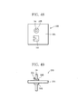
seat cushion of Fig. 41;
- Fig. 43 is a cross-sectional front view for showing
the seat frame of Fig 42;
- Fig. 44 is an exploded perspective view for showing
the weight sensor device of Fig. 41;
- Fig. 45 is a perspective view for showing a state
before a cramp member of Fig. 44 is fixed to the net;
- Fig. 46 is a perspective view for showing a state
after the cramp member is fixed to the net;
- Fig. 47 is a side view for showing a r part of a rod
extending from the cramp member;
- Fig. 48 is a plan view for showing a slider of the
weight sensor device of the third embodiment;
- Fig. 49 is a side view for showing the slider of Fig.
48;
- Fig. 50 is a perspective view for showing a variable
resistor of the weight sensor device of the third
embodiment;
- Fig. 51 is a plan view for showing a state of the
variable resistor of Fig. 50 before a terminal cover is
attached;
- Fig. 52 is a perspective view for showing a state
where the sliding element of the weight sensor device of
Fig. 49 is in contact with resistor strips of the variable
resistor;
- Fig. 53 is a cross-sectional front view for
schematically showing the state where the occupant is
seating on the seat cushion mounted with the weight sensor
device of the third embodiment;
- Fig. 54 is a cross-sectional side view for
schematically showing the state where the occupant is
seating on the seat cushion mounted with the weight sensor
of the third embodiment;
- Fig. 55 is a plan view for showing a modification of
the variable resistor of Fig. 51;
- Fig. 56 is a graph for showing a relationship between
the moving amount of the hook portion and an output of the
weight sensor device with the resistor strips shown in Fig.
55;
- Fig. 57 is a graph for showing a relationship between
the moving amount of the hook portion and an output of the
weight sensor device with the resistor strips shown in Fig.
51;
- Fig. 58 is a plan view for showing a modification of
the variable resistor of Fig 51;
- Fig. 59 is an exploded perspective view for showing a
modification of the weight sensor device of Fig. 44; and
- Fig. 60 is a cross-sectional view for showing a state
where a coil spring shown in Fig. 59 is housed.
-
DETAILED DESCRIPTION OF THE INVENTION
-
Embodiments of the invention will now be described
with reference to the accompanying figures, wherein like
numerals refer to like elements throughout. The
terminology used in the description presented herein is not
intended to be interpreted in any limited or restrictive
manner, simply because it is being utilized in conjunction
with a detailed description of certain specific embodiments
of the invention. Furthermore, embodiments of the
invention may include several novel features, no single one
of which is solely responsible for its desirable attributes
or which is essential to practicing the invention herein
described.
First Embodiment
-
Fig. 1 shows a seat 10 of an automobile. The seat 10
includes a seat cushion 20, a seat back 11, and a headrest
12.
-
As shown in Fig. 2, the seat cushion 20 has a seat
frame 22 and a cushion 21 mounted on the seat frame 22.
The seat frame 22 is substantially box-shaped as opened
upward, having a bottom wall 23 and a peripheral wall 24.
When mounted thereon with the cushion 21, the seat frame 22
cooperates with the cushion 21 to define a bottom chamber
therein.
-
The seat frame 22 is provided with three weight
sensors 30, which are arranged in the longitudinal
direction of the seat frame 22 with a predetermined spacing
therebetween.
-
The weight sensors 30 are each provided with a sensor
unit 40, which is attached to the peripheral wall 24 of the
seat frame 22, that is, a side wall 24a thereof.
Specifically, a unit holder 25 is integrally formed with
the side wall 24a. This unit holder 25 is box-shaped as
projected from the side wall 24a, communicating to the
bottom chamber.
-
The sensor unit 40 is housed in the unit holder 25.
From the sensor unit 40, a sensing wire 70 extends, to be
stretched over between the two side walls 24a and 24b. A
hook 71 is provided at one end of the sensing wire 70 and
engaged with a pair of engagement holes formed in the side
wall 24b.
-
As is clear from Figs. 3 and 4, the sensing wires 70
of the three weight sensors 30 extend parallel to each
other at the same height with respect to the bottom wall 23
of the seat frame 22.
-
As shown in Fig. 5, the sensor unit 40 is provided
with a substantially rectangular parallelepiped-shaped case
41. From a front face 43a of the case 41 is projected a
rotary shaft 42, which is urged to rotate in one direction
by a spiral spring (not shown). The rotary shaft 42 has a
hollow shape, on the inner face of which is formed one pair
of projections 46 shaped substantially triangular in a
cross section. These projections 46 are arranged so that
their respective vertexes may face each other toward a
central axis of the rotary shaft 42.
-
A rotary wheel 60 is attached to the rotary shaft 42.
The rotary wheel 60 includes a disk 62 having a guide
groove 63. The guide groove 63 is formed on an outer
peripheral face of the disk 62. The rotary wheel 60
further includes a shaft 61 projecting from one end face of
the disk 62. The shaft 61 is inserted into the rotary
shaft 42. Specifically, the shaft 61 has one pair of
recesses 65 for receiving the projections 46 of the rotary
shaft 42 therein, so that the shaft 61 and the rotary shaft
42 can mesh with each other to permit the rotary shaft 42
to rotate integrally with the rotary wheel 60.
-
The guide groove 63 of the disk 62 can receive the
above-mentioned sensing wire 70 therein, so that the
sensing wire 70 can be wound around the disk 62.
-
Furthermore, as shown in Figs. 6 and 7, a notch 64 is
formed in an outer periphery portion of the other end face
of the disk 62. The notch 64 is key hole-shaped so as to
communicate into the guide groove 63.
-
The other end of the sensing wire 70, on the other
hand, has a ball 72. The ball 72 is fitted into the notch
64, so that the sensing wire 70 is fixed to the disk 62 as
wound around the disk 62 or the guide groove 63.
-
As shown in Fig. 5, the case 41 has a side face 43b
which is contiguous with the front face 43a. The side face
43b has mounting brackets 44a and 44b at an upper part and
a lower part thereof respectively. In the mounting
brackets 44a and 44b are formed screw holes 45a and 45b
respectively for fixing the case 41 to the unit holder 25.
-
The description related to Figs. 5 through 7 is
summarized as follows: a) the case 41 is fixed to the unit
holder 25 by screwing the mounting brackets 44a and 44b to
the unit holder 25; b) the rotary shaft 42 and the shaft 61
of the disk 62 mesh with each other so as to permit the
rotary wheel 60 to rotate integrally with the rotary shaft
42; and c) the sensing wire 70, as wound around the disk 62
by a predetermined length, is pulled out from the disk 62
in the width direction of the seat frame 22 against the
rotational urging force of the rotary shaft 42 and then is
connected to the side wall 24b of the seat frame 22 through
the hook 71. Therefore, predetermined tension is applied
to the sensing wire 70, which extends along the lower face
of the cushion 20 between the two side walls 24a and 24b of
the seat frame 22.
-
In this construction, when an occupant sits on the
seat cushion 20 to apply his weight on the cushion 20, the
sensing wire 70 is deformed downward together with the
cushion 20. Such deformation of the sensing wire 70 causes
itself to be pulled out from the disk 42 of the sensor unit
40. This pulled-out operation of the sensing wire 70 in
turn causes the rotary wheel 60 or the rotary shaft 42 of
the sensor unit 40 to be rotated. That is, the deformation
of the sensing wire 70 is converted into the rotation of
the rotary shaft 42.
-
To detect the rotation of the rotary shaft 42, a
variable resistor 50 such as shown in Fig. 8 is
incorporated in the case 42 of the sensor unit 40. The
variable resistor 50 has an insulation board 51 and two
resistor strips 52 and 53 formed on this insulation board
51. This insulation board 51 is made of, for example,
laminate including glass and epoxy resin or ceramic. The
resistor strip 52 is downward U-shaped as shown in Fig. 8.
The resistor strip 53, on the other hand, is annular in
shape and arranged in the resistor strip 52 concentrically
therewith. That is, the resistor strip 53 is arranged
concentrically with an arc of the resistor strip 52.
-
The resistor strip 53 has an extension, which
protrudes in parallel with the two end portions of the
resistor strip 52. The resistor strip 52 has terminals 54
and 56 at the ends thereof respectively, while the resistor
strip 53 has a terminal 55 at an end of the extension
thereof. These resistor strips 52 and 53 are formed for
example by printing. Furthermore, from the terminals 54,
55, and 56 extend lead wires 57, 58, and 59 respectively.
-
Moreover, the variable resistor 50 has a sliding
element 101. The sliding element 101 includes a leaf
spring formed by bending a metal sheet having good
conductivity, which is attached to the rotary shaft 42.
The sliding element 101 has two legs 102 and 103. The
sliding element 101 is pressed against the insulation board
51 so that the legs 102 and 103 can be in contact at all
times with the resistor strips 52 and 53 respectively.
-
As mentioned above, when the rotary shaft 42 rotates,
the legs 102 and 103 of the sliding element 101 slide on
the resistor strips 52 and 53 respectively, in accordance
with the rotation angle or number of revolutions of the
rotary shaft 42. The resultant displacement of these legs
102 and 103 in turn brings about a change in electrical
resistance value between the terminals 54 and 55 and a
change in electrical resistance value between the terminals
55 and 56. If a predetermined voltage is applied between
the terminals 54 and 56 beforehand, therefore, the rotation
angle of the rotary shaft 42 can be determined by measuring
the value of a voltage appearing at the terminal 55. Since
the rotary shaft 42 rotates due to the deformation of the
sensing wire 70, that is, the weight applied on the cushion
21, the weight can be determined by measuring the voltage
value.
-
As shown in Figs. 9 and 10, when the occupant sits on
the seat cushion 20, the cushion 21 is deformed with
respect to its initial state in which no weight is applied
thereon and moves downward. In accordance with such
deformation of the cushion 21, the sensing wire 70 is
stretched by the cushion 21 so that the sensing wire 70 is
deformed downward. As described above, as the sensing wire
70 is deformed, the rotary wheel 60 or the rotary shaft 42
of the sensor unit 40 rotates. Then, in association with
the rotation of the rotary shaft 42, the legs 102 and 103
of the sliding element 101 shown in Fig. 8 slide on the
resistor strips 52 and 53 respectively. As a result, there
occurs the change in electrical resistance value between
the lead wire 57 (terminal 54) and the lead wire 58
(terminal 55) and the change in electrical resistance value
between the lead wire 58 (terminal 55) and the lead wire 59
(terminal 56).
-
As shown in Figs. 2 and 3, the three weight sensors 30
are arranged below the cushion 21 and, therefore, each of
the sensors 30 output a voltage value based on such a
change in electrical resistance as to correspond to the
weight applied on the sensing wire 70 of their own.
-
A correlation between the occupant's weight and an
output of each of the weight sensors 30 has obtained
beforehand by letting occupants having various body weights
sit on the seat cushion 20. Based on thus obtained
correlation and an output of each of the weight sensors 30,
therefore, it is possible to determine the weight, that is,
the body weight of the passenger.
-
It is to be here noted that, an average or a total sum
of the outputs of each of the weight sensors 30 may be used
to obtain the above-mentioned correlation. Further,
instead of the average or total sum of the outputs, a value
representative of the outputs may be used; the value can be
obtained by processing the outputs of weight sensors 30 in
accordance with other computing method.
-
Actually, when the occupant sits on the seat 10, the
occupant's weight is applied as distributed to the seat
cushion 20, the seat back 11, the head rest 12, a foot rest,
a pedal and the like. Of these distributed weights, the
one applied to the seat cushion 20 is the largest in
proportion, so that based on this largest weight the
occupant's body weight can be approximated in calculation.
-
The weight sensor 30 according to the present
embodiment has a very simple configuration comprising only
the sensor unit 40 and the sensing wire 70 and can be
provided very inexpensively.
-
Furthermore, in the present embodiment, three weight
sensors 30 have been provided, but the number of the weight
sensors provided may be changed arbitrarily.
-
Figs. 11 and 12 show a modification of the weight
sensor 30 of the present embodiment
-
Between the right and left side walls 24a and 24b and
between the front and rear walls 24c and 24d of the seat
frame 22 are stretched each two sensing wires 70 at the
same height with respect the bottom of the seat frame 22.
To one end of each of the sensing wires 70 is connected the
sensor unit 40, which is fixed to one portion of the
peripheral wall 24 of the seat frame 22. Furthermore, the
other end of the sensing wire 70 is connected to the other
portion of the peripheral wall 24 facing to the one portion
thereof.
-
The sensing wires 70 stretched over the bottom of the
seat frame 22 intersect with each other. Each of the
intersections is provided with a buffer member 75 so that
the mutually intersecting sensing wires 70 may not
interfere with each other.
-
As shown in Fig. 13, at the other end thereof, the
sensing wire 70 according to the present modification has a
ball 71a similar to the ball 72 in place of the hook 71 of
Fig. 5.
-
As shown in Figs. 11 and 12, the front wall 24c of the
seat frame 22 has an elevation 24e. This elevation 24e
rises from the bottom wall 23 of the seat frame 22 as
extending between the side walls 24a and 24b thereof.
-
The elevation 24e has a substantially trapezoid-shape
and a substantially rectangular top face. Furthermore, the
elevation 24e has a slant face 24f inclined from the top
face toward the rear wall 24d. Between this slant face 24f
and the rear wall 24d are stretched over two pair of
meandering springs 26, each of the meandering springs 26
has a shape in which an S-character is repeated. These
meandering springs 26 support the seat cushion mounted on
the seat frame 22.
-
As shown in Figs. 14 and 15, the sidewall 24b and the
slant face 24f are each provided with two retaining
portions 27, those on the slant face 24f being disposed
between the meandering springs 26 paired with each other.
-
The retaining portions 27 of the side wall 24b are,
for example, hollow semi-cylinder shaped, extending along
the side wall 24b as shown in Fig. 14. More specifically,
the retaining portion 27 is made of a substantially vault
roof-shaped plate rising from the side wall 24b and has a
substantially arc-shaped transverse section. The retaining
portion 27 has at its middle a vertical slit 27b formed
thereon, an upper part of which continues to a hole 27a
having a little larger diameter than that of the ball 71a.
Furthermore, as shown in Fig. 15, the retaining portion 27
of the slant face 24f of the elevation 24e is also hollow
semi-cylinder shaped similar to the retaining portion 27 of
the side wall 24b and has the hole 27a formed thereon which
continues to the upper part of the slit 27b.
-
As mentioned above, the buffer member 75 shown in Figs.
16 and 17 serves to prevent the mutually intersecting
sensing wires 70 from interfering with each other. The
buffer member 75 includes a main body 75b made of felt. The
main body has a substantially rectangular shape, for
example. The buffer member 75 further includes a pair of
metal hook members 75b, which project from the two sides of
the main body 75a respectively.
-
In the main body 75a are formed four insertion holes
for insertion of the sensing wire 70, these insertion holes
are arranged substantially at the respective four corners
of a lozenge. Specifically, on one longer side portion of
the main body 75a are formed the insertion holes 75c and
75d, while on the other longer side portion thereof are
formed insertion holes 75e and 75f. The insertion holes
75c and 75f are positioned on one diagonal of the lozenge,
through which is inserted, for example, the sensing wire 70
stretched over between the side faces 24a and 24b. The
insertion holes 75d and 75e, on the other hand, are
positioned on the other diagonal, through which is inserted,
the sensing wire 70 stretched over between the front and
rear faces 24c and 24d.
-
Ends of the paired hook members 75b are bent toward
the main body 75a so as to form hooks 75g and 75h
respectively. That is, both the hooks 75g and 75h have
substantially a J-shape and hook mouths facing each other.
As shown in Fig. 17, the hooks 75g and 75h holds the
corresponding meandering springs 26. It is to be noted
that the material of the main body 75a is not limited to
felt but may be any material as far as it will not cause
the sensing wire 70 to wear.
Second Embodiment
-
The following will describe a weight sensor device of
the second embodiment according to the present invention.
-
As shown in Figs. 18 to 20, the seat cushion 20 is
provided with a net 90, which is arranged in the seat frame
22. The cushion 21 is mounted on the net 90. The net 90
includes two side bars 91 which extend along the side walls
24a and 24b of the seat frame 22 respectively and, for
example, six cross bars 92, each of which connects these
side bars 91 to each other. Between each side bar 91 and
the corresponding side wall 24a or 24b is stretched over a
plurality of (six in total in the present embodiment) coil
springs 93 for supporting the net 90.
-
Between the net 90 and each of the side walls 24a and
24b is arranged a plurality of (four in total in the
present embodiment) weight sensors 30.
-
As shown in Fig. 21, the weight sensor 30 comprises
the sensor unit 40 and a hook member 80. The case 41 of
the sensor unit 40 is fixed to the corresponding side wall
24a or 24b. The hook member 80 connects the rotary shaft
42 of the sensor unit 40 and the corresponding side bar 91
of the net 90.
-
More specifically, the hook member 80 has a hook plate
81 and a shaft projecting from one end of the hook plate 81,
which shaft 82 is similar in shape to the above-mentioned
shaft 61 and fitted into the rotary shaft 42 of the case 41.
The hook member 80, therefore, rotates integrally with the
rotary shaft 42.
-
Both ends of the hook plate 81 have a substantially
semi-circle shape, respectively, for example. In the other
end portion of the hook plate 81 is formed an elongated
hole 84, which extends toward one end of the hook plate 81.
The end of the elongated hole 84 positioned at the one end
of the hook plate 81 is opened through an opening 85 to a
side edge of the hook plate 81 so that the other end of the
hook plate 81 can form a hook 86. In this configuration,
the width of the elongated hole 84 and the opening 85 are
set slightly larger than the diameter of the side bar 91.
It is thus possible to have the hook 86 of the hook member
80 engaged at the side bar 91 of the net 90, in such a
configuration that the side bar 91 is free to slide in the
elongated hole 84 of the hook plate 81.
-
As shown in Fig. 21, the case 41 of the sensor unit 40
has a pair of locking portions 47 at the upper end portion
of the side face 43b. The locking portions 47 are arranged
horizontally with a predetermined spacing set therebetween
and project from the side face 43b. The top face of each
of the locking portions 47 is flat and substantially
perpendicular to the side face 43b. Furthermore, the
locking portions 47 have sector shape as viewed in a
vertical section.
-
Furthermore, the side face 43b of the case 41 is
provided with a pinch plate 48, which is arranged below the
locking portions 47. This pinch plate 48 is substantially
T-shaped as viewed in a cross section and connected to the
side face 43b through a guide portion 49 thereof.
-
The side wall 24a or 24b of the seat frame 22, on the
other hand, has a rectangular guide groove 29 formed
therein, which extends downward from the upper edge of the
side wall. The guide groove 29 can receive the guide
portion 49 of the pinch plate 48 therein. Therefore, the
sensor unit 40 or the case 41 is attached to the side wall
24a or 24b by inserting the guide portion 49 of the pinch
plate 48 into the guide groove 29 up to the bottom thereof.
Then, the side wall is sandwiched by the side face 43b of
the case 41 and the pinch plate 48.
-
Furthermore, the side wall has two locking holes 27
formed therein as to correspond to the above-mentioned
locking portions 47. As shown in Figs. 22 to 24, therefore,
when the sensor unit 40 is mounted, the locking portions 47
of the case 41 are fitted into the corresponding locking
holes 27 in the side wall. The locking holes 27 prevent
the locking portions 47 from being lifted so that the
sensor unit 40 cannot readily be pulled out from the side
wall of the seat frame 22.
-
As shown in Figs. 25 and 26, when an occupant sits on
the seat cushion 20, the cushion 21 is deformed downward
due to the weight of the occupant applied thereon. Such
deformation of the cushion 21 causes the net 90 to be
displaced downward against the urging force of the coil
springs 93. This displacement in turn causes the hook
member 80 of the sensor unit 40 to turn. As a result, the
weight sensors 30 according to this second embodiment can
detect the weight of the occupant.
-
More specifically, when the occupant is not seated on
the seat cushion 20, as shown in Fig. 27, the hook 86 of
the hook member 80 is engaged at the side bar 91 of the net
90 as positioned above the rotary shaft 42 of the sensor
unit 40. When the occupant sits on the seat cushion 20, on
the other hand, the net 90 is displaced downward. This
displacement then causes the hook member 80 to turn around
the axis of the rotary shaft 42, thus permitting the side
bar 91 to slide in the elongated hole 84 in the hook member
80 (in a direction of an arrow B) as shown in Fig. 28. The
hook member 80 is thus turned to then rotate the rotary
shaft 42, which causes the sliding element 101 of the
variable resistor 50 to move, which in turn gives rise to a
change in output of the variable resistor 50.
-
Of course, by the second embodiment also, almost the
same correlation as that by the first embodiment has
obtained beforehand.
-
The weight sensor 30 has also a simple configuration
comprising only the sensor unit 40 and the hook member 80
and can be provided inexpensively.
-
The present embodiment does not restrict the number of
the weight sensors provided to four either.
-
Fig. 29 shows a modification net 95. This net 95
differs from the net 90 only in one respect that hook
catching portions 98 are provided to each of two side bars
91. These hook-catching portions 98 are substantially C-shaped.
an open side of which is linked to the side bar 91,
projecting downward from therefrom.
-
In the above-mentioned net 95, as shown in Fig. 30,
hook member 80 is engaged not at the side bar 91 of the net
95 but at a horizontal bar 99 of the hook catching portion
98. In this case, the sensor unit 40 is mounted at a lower
position than that when the net 90 is used. In this
configuration, when an occupant sits on the seat cushion 20
and the net 95 is resultantly displaced downward, the hook
86 of the hook member 80 can be displaced downward below
the rotary shaft 42 of the sensor unit 40. That is, as
shown in Fig. 31, even if the net 95 is displaced downward,
the sensor unit 40 can stay below the side bar 91 always,
thus providing such an advantage as to avoid interference
between the sensor unit 40 and the cushion 21.
-
Fig. 32 shows a modification of the sensor case 41.
In this case, a pinch plate 48a and a guide portion 49a of
the case 41 of Fig. 32 differs from the pinch plate 48 and
guide portion 49 of Fig. 14 in a respect that these extend
to the upper end of the side face 43b.
-
Figs. 33 to 35 show states where the sensor unit 40 is
mounted to the side wall 24a or 24b of the seat frame 22.
-
As is clear from Figs. 33 to 35, a pair of engagement
portions 47a is provided on the both o sides of the guide
groove 29 respectively on the side wall of the seat frame
22. The engagement portions 47a are a triangular
protrusion. More specifically, the engagement portions 47a
are substantially rectangular as viewed from the side of
the side wall and substantially right-angle triangular as
viewed in a vertical section. That is, the engagement
portion 47a has a slant face extending from the upper edge
to the lower edge of the side wall and a horizontal face
interconnecting the lower edge of this slant face and the
side wall.
-
When the guide portion 49a of the case 41 is inserted
into the guide groove 29 in the side wall of the seat frame
22, the side face 43a of the case 41 goes beyond the pair
of the engagement portions 47a. When the case 41 is
mounted to the side wall, therefore, the lower end of the
engagement portion 47a butts against the top face of the
case 41, thus preventing the case 41 from readily going out
of the guide groove 29.
-
As shown in Fig. 36, the hook member 80 of Fig. 21 is
replaced by a combination of a rotary wheel 60a, a wire 70a,
and a substantially spherical ball 71a. The rotary wheel
60a is almost the same as the rotary wheel 60 of Fig. 13,
while the wire 70a is used in place of the sensing wire 70
of Fig. 13. The sensor unit 40 is almost the same as that
of Fig. 21.
-
As shown in Figs. 37 and 38, the ball 71a is engaged
at the net 90 through a retaining piece 73. The retaining
piece 73 is formed of a substantially rectangular plate
member, one end of which is formed as a substantially U-shaped
bend 73c and also has a retaining hole 73d formed
therein having a little larger inner diameter than the
diameter of the ball 71a as well as a slit 73e formed
therein which is contiguous to the hole 73d. By fitting
the ball 71a into the retaining hole 73d to pass t the wire
70a through the slit 73e and then shifting the ball 71a so
that the ball 71a can be received on the bottom of the U-shaped
bend 73c, the wire 70a is caught by the retaining
piece 73. Then, the retaining piece 73 is fixed to the
side bar 91 by winding the other end 73a thereof around the
side bar 91.
-
By thus connecting the sensor unit 40 and the net 90
to each other, the wire 70a has its one end wound around
the rotary wheel 60a or the guide groove 63a thereof owing
to the tension of a return spring (not shown) and also is
stretched over between the net 90 and the rotary wheel 60a.
-
As shown in Fig. 39 and 40, the weight sensors 30 are
mounted to the seat frame 22. When the net 90 is displaced
downward due to the weight of an occupant applied thereon,
the net 90 pulls the wire 70a, which in turn rotates the
rotary wheel 60a.
Third Embodiment
-
Fig. 41 shows the seat cushion 20 provided with weight
sensors according to the third embodiment according to the
present invention.
-
As is clear from FIG, 41, the net 90 further includes
a center bar 94 at the center between the two side bars 91.
The bars 91, 92, and 94 that make up the net 90 are all
made of spring wires, so that the net 90 is a spring net in
the present embodiment. When an occupant sits on the seat
cushion 20, therefore, the net 90 deforms together with the
cushion 20 and the coil springs 93, thus improving the
comfortableness in sitting.
-
In this third embodiment, as shown in Figs. 42 and 43,
one weight sensor 30 is provided between the seat frame 22
and the net 90.
-
The weight sensor 30 has a first hook member 31 which
interconnects a sensor unit 40 and the side bar 91 of the
net 90 and a second hook member 32 which interconnects the
sensor unit 40 and the side wall 24b of the seat frame 22.
-
As shown in Fig. 44, the sensor unit 40 has a case 401
and a cover 402. The case 401 and the cover 402 are
connected to each other by bolts 401g. The these bolts
401g are screwed into threaded holes 401c in the case 401
through holes 402b in the cover 402, respectively.
-
On the top face of the case 401 is mounted a slider
100. This slider 100 can slide along a groove 401b. The
groove 401b is opened to the upper face and one end face of
the case 401.
-
The slider 100 is connected to the first hook member
31 through a rod 33, which slidably extends in the groove
401b. The first hook member 31, therefore, can reciprocate
smoothly.
-
Furthermore, the cover 402 has a protrusion 402a
formed thereon. When the cover 402 is attached to the case
401, the protrusion 402a is inserted into the groove 401b
in the case 401 to thereby press down the rod 33 in the
groove 401b, thus guiding the sliding of the rod 33.
-
As is clear from Fig. 44, the case 401 has two
protrusions 401d formed at the opposite ends on the top
face thereof. These protrusions 401d support the
insulation board 51, of the variable resistor 50, extending
therebetween. The protrusions 401d thus preserves a
sufficient space between the insulation board 51 and the
slider 100 so that the slider 100 can slide without
interfering with the insulation board 51.
-
In this configuration, the second hook member 32 is
fixed at the other face of the case 401.
-
As shown in Fig. 45, the first hook member 31 has a
pair of clamp plates 31a, which are connected to each other
through a pair of hinges 31c. One of the clamp plates 31a
is connected to the rod 33 and has a pair of latch grooves
31e formed in the rod-side edge thereof. The other clamp
plate 31a has a pair of latch claws 31d, which can engage
with the latch grooves 31e respectively.
-
Furthermore, each of the clamp plates 31a has a groove
31b formed thereon which is semi-circle shaped as viewed in
a cross section.
-
In such a configuration, with the groove 31b of the
rod-side clamp plate 31a as fitted to the side bar 91 of
the net 90, the other clamp plate 31a is turned around the
hinges 31c to be superposed on the rod-side clamp plate 31a,
thus engaging the latch claws 31d in the latch grooves 31e
respectively. Accordingly, as shown in Fig. 46, the first
hook member 31 is connected to the side bar 91 in such a
state that the side bar 91 is sandwiched by the pair of the
clamp plates 31a, that is, in such a state that the side
bar 91 is passed into the passage defined between the
grooves 31b of these clamp plates 31a.
-
It is to be noted that the second hook member 32 may
also have almost the same fold-type construction as that of
the first hook member 31.
-
As shown in Fig. 47, a linkage portion 34 extends
upward from the rod 33 of the first hook member 31 for
interconnecting the rod 33 and the slider 100 and has a
rectangular cross section.
-
More specifically, as shown in Figs. 48 and 49, the
slider 100 has a plate-shaped base 102, through which the
above-mentioned linkage portion 34 passes through upper and
lower fixtures 103. These fixtures 103 are attached to the
upper and lower surfaces of the base 102 respectively and
each have a rectangular through hole. The through hole of
the fixtures 103 permits the linkage portion 34 to pass
through but prevents the base n 102 from turning with
respect to the linkage portion 34.
-
Furthermore, the base 102 is mounted with the sliding
element 101 on the upper surface thereof.
-
As shown in Figs. 50 and 51, the insulation board 51
of the variable resistor 50 has a plurality of (two in the
present embodiment) resistor strips 52 and 53. In the case
of the present embodiment, for example, the resistor strip
52 is looped in a rectangle, while the resistor strip 53 is
substantially T-shaped and arranged inside the resistor
strip 52. That is, the resistor strip 52 goes around the
resistor strip 53 in such a configuration that these
resistor strips 52 and 53 extend in a longitudinal
direction of the board 51 and have parts thereof arranged
parallel to each other.
-
Both terminals 54 and 56 of the resistor strip 52 and
a terminal 55 of the resistor strip 53 are connected to
lead wires, respectively.
-
Furthermore, the board 51 is provided with a terminal
cover 106 for covering the terminals 54, 55, and 56.
-
As shown in Fig. 44, the cover 402 has a notch 402c,
through which the above-mentioned lead wires are introduced
into the sensor unit 40 or the cover 402.
-
As shown in Fig. 52, two legs 102 and 103 of the
sliding element 101 are constantly kept in contact with the
resistor strips 52 and 53 respectively.
-
As shown in Figs. 53 and 54, when an occupant sits on
the seat cushion 20, the occupant's weight is applied to
the cushion 21 to displace the net 90 downward (in the
arrow direction). As the net 90 is thus displaced downward,
the slider 100 connected to the first hook member 31
through the rod 33 slides on the top face of the case 401.
That is, a relative position between the slider 100 and the
board 51 changes. A change in this relative position
causes the legs 102 and 103 of the sliding element 101 to
move on the resistor strips 52 and 53 respectively. This
results in a change in output of the variable resistor 50.
-
In the weight sensor 30 according to the present
embodiment, the deformation or displacement of the net 90
owing to a weight applied thereon is output from the
variable resistor 50 as a change in voltage value, thus
providing a simple and inexpensive control circuit which is
not readily influenced by electromagnetic waves.
-
As shown in Fig. 55, the insulation board 51 may
further includes a conductive layers 1 59 made of carbon or
like, which conductive layers 59 are inserted as part of
the resistor strip 52 or 53 or partially stacked on the
strip. In this case, as shown in Fig. 56, the output of
the variable resistor 50 changes stepwise as the moving
amount of the first hook member 31 changes.
-
In contrast, in the case of such a variable resistor
50 having the resistor strips 52 and 53 as shown in Fig. 51,
the output of the variable resistor 50 changes straightly
as the moving amount of the first hook member 31 changes.
-
Furthermore, the resistor strips 52 and 53 may have
such a pattern as shown in Fig. 58. In this case, the
resistor strips 52 has the terminal 54 only at its one end,
while the resistor strip 53 is divided into a plurality of
resistor pieces 53a to 53c, which also have terminals 54b
to 54d respectively. Furthermore, in this case, these
resistor strips may each be made of a conductive material
such as carbon in place of an electrical resistant material.
-
It is to be noted that the present invention is not
limited to the above-mentioned embodiments but may be
modified variously without departing from the scope thereof.
-
Fig. 59 is a perspective view for showing a
modification of the weight sensor 30 of the third
embodiment according to the present invention and Fig. 60
is a cross-sectional side view for showing a state where a
coil spring 36 used in this weight sensor 30 is attached.
It is to be noted that in both Figs. 59 and 60, the
insulation board 50, the slider 100, and the like are
omitted for simplification.
-
This modification of the weight sensor 30 features
that the coil spring (urging member) 36 is provided to the
first hook member 31. Preferably the coil spring 36 has a
larger inner diameter than the largest cross section of the
first hook member 31. In the case 401 is formed such a
spring chamber 401e for insertion of the coil spring 36.
The spring chamber 401e extends along the groove 401b and
surrounds part of the groove 401b. More specifically, the
distal end portion of the rod 33 is slidably inserted into
a hole portion of the groove 401b.
-
Furthermore, the first hook member 31 has such a rod
portion 35 extending downward from the linkage portion 34.
The rod portion 35 cooperates with the linkage portion 34
to form a spring seat for one end of the coil spring 36.
Moreover, the cover 402 has a front end wall 402d as a
spring seat for the other end of the coil spring 36. The
front end wall 402d is fixed to the case 401 by bolts (not
shown). Therefore, the case 401 and front end wall 402d
has threaded holes 401f and through holes 402e for screwing
the bolts, respectively. As shown in Fig. 60, the coil
spring 36 is mounted between the spring seat of the first
hook member 31 and the front end wall 402d of the cover 402
so as to absorb the shock applied on the first hook member
31 when an occupant is seated, thus stabilizing the sliding
of the first hook member 31.
-
Where technical features mentioned in any claim are followed by reference signs, those reference
signs have been included for the sole purpose of increasing the intelligibility of the claims and
accordingly, such reference signs do not have any limiting effect on the scope of each element
identified by way of example by such reference signs.