JP2005337770A - Seating weight measuring apparatus - Google Patents
Seating weight measuring apparatus Download PDFInfo
- Publication number
- JP2005337770A JP2005337770A JP2004154153A JP2004154153A JP2005337770A JP 2005337770 A JP2005337770 A JP 2005337770A JP 2004154153 A JP2004154153 A JP 2004154153A JP 2004154153 A JP2004154153 A JP 2004154153A JP 2005337770 A JP2005337770 A JP 2005337770A
- Authority
- JP
- Japan
- Prior art keywords
- weight measuring
- holding body
- support
- vehicle body
- seating
- Prior art date
- Legal status (The legal status is an assumption and is not a legal conclusion. Google has not performed a legal analysis and makes no representation as to the accuracy of the status listed.)
- Withdrawn
Links
Images


Classifications
-
- G—PHYSICS
- G01—MEASURING; TESTING
- G01G—WEIGHING
- G01G19/00—Weighing apparatus or methods adapted for special purposes not provided for in the preceding groups
- G01G19/40—Weighing apparatus or methods adapted for special purposes not provided for in the preceding groups with provisions for indicating, recording, or computing price or other quantities dependent on the weight
- G01G19/413—Weighing apparatus or methods adapted for special purposes not provided for in the preceding groups with provisions for indicating, recording, or computing price or other quantities dependent on the weight using electromechanical or electronic computing means
- G01G19/414—Weighing apparatus or methods adapted for special purposes not provided for in the preceding groups with provisions for indicating, recording, or computing price or other quantities dependent on the weight using electromechanical or electronic computing means using electronic computing means only
- G01G19/4142—Weighing apparatus or methods adapted for special purposes not provided for in the preceding groups with provisions for indicating, recording, or computing price or other quantities dependent on the weight using electromechanical or electronic computing means using electronic computing means only for controlling activation of safety devices, e.g. airbag systems
Abstract
Description
本発明は、車両用シートに設置され、着座者の体重に相当する重量を測定する着座重量測定器に関するものである。 The present invention relates to a seating weight measuring device that is installed in a vehicle seat and measures a weight corresponding to the weight of a seated person.
従来から、車両用シートには、例えば、シートベルトの装着状態をシートベルトバックルへのシートベルトタングの挿入に連動する検出スイッチで検出する際、そのシートへの着座の有無に連動して行うようにした着座検出器が周知である。 Conventionally, for example, when detecting a seat belt wearing state with a detection switch that is linked to the insertion of a seat belt tongue into a seat belt buckle, the vehicle seat is linked to the presence or absence of seating on the seat. Such a seating detector is well known.
この着座検出器は、車両用シートのシートスライドレールやシートクッション内に設置したスイッチのオン・オフにより着座状態を検出するもので、着座を検出したときにシートベルトの装着がなされていない場合にはシートベルトの装着を促すインジケータランプを点灯させるといった報知を行う。 This seating detector detects the seating state by turning on and off the switch installed in the seat slide rail or seat cushion of the vehicle seat, and when seating is not detected when seating is detected Performs a notification such as turning on an indicator lamp for urging the user to wear the seat belt.
一方、近年では、エアバッグを作動させる際にインフレーターを制御することによってエアバッグの展開量(膨出量)を複数段階としたり、シートベルトのベルト張力を複数段階としたいといった要望がある。 On the other hand, in recent years, there has been a demand for controlling the inflator when the airbag is operated to set the airbag deployment amount (inflated amount) in a plurality of stages, and for making the belt tension of the seat belt a plurality of stages.
これは、エアバッグを展開させる際の圧力やシートベルトのベルト張力を、大人の場合と子供の場合とで異ならせたいという要望に起因するものである。 This is due to the desire to vary the pressure when deploying the airbag and the belt tension of the seat belt between adults and children.
従って、このようなエアバッグの作動制御によるエアバッグの展開量やシートベルトのベルト張力を複数段階に設定する場合には、上述した着座の有無のみを検出する着座検出器を流用したのでは不可能である。 Therefore, when the airbag deployment amount and the belt tension of the seat belt by the airbag operation control are set in a plurality of stages, it is not possible to use the above-described seating detector that detects only the presence or absence of seating. Is possible.
図9は、このような着座した人の体重を少なくとも複数段階で検出することによってエアバッグの展開量やシートベルトのベルト張力を複数段階とすることを可能とする着座重量測定器の一例を示し(例えば、特許文献1参照)、図9(A)は着座重量測定器の縦断面図、図9(B)は重量検出部の縦断面図である。 FIG. 9 shows an example of a seating weight measuring apparatus that can detect the weight of a seated person in at least a plurality of stages and thereby make the airbag deployment amount and the belt tension of the seat belt in a plurality of stages. (For example, refer to Patent Document 1), FIG. 9A is a longitudinal sectional view of a seating weight measuring device, and FIG. 9B is a longitudinal sectional view of a weight detection unit.
図9において、着座重量測定器1は、座席レール2にナット3を介して固定される支持体4を備えている。
In FIG. 9, the seating
この支持体4は、座席レール2に形成された孔2aの開口形状と略一致してラジアル方向の回転を規制するように面取りされた断面略小判形状の固定軸4aが一端から突出されている。この固定軸4aの外周にはナット3と螺合するためのネジ溝が形成されている。また、支持体4の他端にはケーブル貫通孔4bを形成した突出部4cが形成されている。さらに、支持体4には、断面円柱状の凹部4dが形成されていると共に、ケーブル貫通孔4cと凹部4dとの間を中空とした空間部4eとが形成されている。また、支持体4は固定軸4aを除いた他端側が車両用シート本体(全体図省略)の一部を構成するアーム5に形成された包囲部5aに離間状態で包囲されている。この際、突出部4cは包囲部5aに形成された開口5bと係合している。さらに、ケーブル貫通孔4bには、保形性を有する樹脂製の円筒状カラー6の一端が保持されている。尚、中空部4eは、例えばフライス加工によって形成され、座席力Fによる負荷(荷重)を受けた際の応力集中(切欠き効果)を減少させるために、内壁面の隣接する壁面管を丸みのある湾曲した壁面で連続させている。
The
この円筒状カラー6には検出信号送信用のケーブル7が貫通している。ケーブル7の一端には、凹部4dに臨む検出体8が設けられている。
A detection
検出体8は、図9(B)に示すように、常時は凹部4dと略同軸上に位置しており、凹部4dの内壁面と360°略等間隔で離間している。また、検出体8は、その先端に構成される永久磁石(磁気発生手段)8Aと磁気式のセンサー(磁気検出手段)8Bとを有しており、このセンサー8BがホールICとして形成されている。尚、常時は、永久磁石8A及びセンサー8Bが互いに凹部4dと同軸上に配置されている。即ち、永久磁石8Aの磁界軸が支持体4の軸線に沿って延びている。
As shown in FIG. 9B, the
このような構成において、車両用シート本体に着座者がいた場合、その着座者の体重に相当する測定すべき座席力Fがアーム5を介して支持体4の突出部4cに伝達される。この結果、支持体4は、座席レール2内に片持ち式に支承されていることに基づき変形するため、この変形量を検出体8と凹部4dとの変位方向並びに変位量とで測定することにより着座者の体重を測定する。
In such a configuration, when there is a seated person on the vehicle seat body, a seating force F to be measured corresponding to the weight of the seated person is transmitted to the protruding portion 4 c of the
すなわち、中空部4eを有する支持体4が変形しても、円筒状カラー7は支持体4の変形に関与せずに変形しない。これにより、円筒状カラー7は、その軸線が支持体4の軸線に対して傾斜することとなり、検出体8と凹部4dとの相対位置が変化する。検出体7の外周を構成する永久磁石8Aの磁束線は、その磁界強度が半径方向の狭くなった領域で増大する。従って、その磁界強度の変化をセンサー8Bによって検出することによって、着座者の体重を測定することができる。
That is, even if the
この際、座席力Fによる支持体4の変形の大きさは、支承箇所間の距離、即ち座席レール2の孔2aとアーム5の開口5bとの間の距離に依存している。
At this time, the magnitude of the deformation of the
ところで、上記の如く構成された着座重量測定器にあっては、検出体7の周囲360°の全周に凹部4dが位置している。
By the way, in the seating weight measuring device configured as described above, the concave portion 4d is located on the entire circumference of the
これに対し、検出体7の検出精度は、検出体7を車両用シートに装着した際の固定作業時の負荷(例えば、ナット3の締め付け力)を考慮しなければならない。また、シートを車両に取り付けるときに発生するねじれによる負荷のために永久磁石8Aが車体水平方向(図9(B)中の左右の矢印←→方向)に変位してしまい、この結果誤測定を起こす可能性もある。
On the other hand, the detection accuracy of the
従って、検出体7の軸線と凹部4dの軸線とを同軸上に配置するのは非常に困難であり上記したように誤測定の要因となってしまうばかりでなく、その取り付け作業に熟練を要したり、測定精度の確認・調整作業を余儀なくされるといった作業コストの高騰要因ともなるという問題が生じていた。
Therefore, it is very difficult to arrange the axis of the
本発明は、上記問題を解決するため、測定精度を必要以上に設定することなく充分な測定精度を維持したものでありながら、誤測定を防止することができ、しかも、構成の簡素化による作業コストの高騰を防止することができる着座重量測定器を提供することを目的とする。 In order to solve the above problem, the present invention can prevent erroneous measurement while maintaining sufficient measurement accuracy without setting the measurement accuracy more than necessary, and also enables the work by simplifying the configuration. An object of the present invention is to provide a seating weight measuring device capable of preventing an increase in cost.
その目的を達成するため、請求項1に記載の着座重量測定器は、一方側が車体に対して相対位置が固定され且つ他方側が車両用シート側からの荷重量に応じて変位する支持体と、前記支持体の他方側に中途部が保持された保形性を有する保持体と、前記支持体の変位を検出するために、前記保持体の先端部に対向するように前記支持体に設けられ、車体上下方向における前記保持体先端部への対向距離が車体水平方向における前記保持体先端部への対向距離よりも小さくされた保持体対向部と、前記保持体の先端に設けられた磁気検出手段とを備え、車両用シート側からの荷重量に応じた前記支持体の変位に連動する、前記車体上下方向における前記対向距離の変化に伴う磁界強度の変化に基づいて車両用シート側からの荷重量を測定することを特徴とする。
In order to achieve the object, the seating weight measuring device according to
請求項2に記載の着座重量測定器は、前記保持体対向部は第1磁気発生手段を備え、前記磁気検出手段は、前記第1磁気発生手段から発生され前記車体上下方向における前記対向距離に応じて変化する磁界強度を検出することを特徴とする。
The seating weight measuring device according to
請求項3に記載の着座重量測定器は、前記第1磁気発生手段が前記保持体よりも車体上方にのみ設けられていることを特徴とする。
The seating weight measuring device according to
請求項4に記載の着座重量測定器は、前記保持体の先端に設けられた第2磁気発生手段を備え、前記磁気検出手段は、前記第2磁気発生手段から発生され前記車体上下方向における前記対向距離に応じて変化する磁界強度を検出することを特徴とする。
The seating weight measuring device according to
請求項5に記載の着座重量測定器は、前記保持体対向部は、前記車体水平方向の少なくとも一方側を開放した構造であることを特徴とする。
The seating weight measuring instrument according to
請求項6に記載の着座重量測定器は、車体上下方向における剛性が車体水平方向における剛性よりも小さく構成され、一方側が車体に対して相対位置が固定され且つ他方側が車両用シート側からの荷重量に応じて変位する支持体と、前記支持体の他方側に中途部が保持された保形性を有する保持体と、前記支持体の変位を検出するために、前記保持体の先端部に対向するように前記支持体に設けられた保持体対向部と、前記保持体の先端に設けられた磁気検出手段とを備え、車両用シート側からの荷重量に応じた前記支持体の変位に連動する、前記保持体対向部の前記保持体先端部への対向距離の変化に伴う磁界強度に基づいて車両用シート側からの荷重量を測定することを特徴とする。
The seating weight measuring device according to
請求項7に記載の着座重量測定器は、前記磁気検出手段は、前記第3磁気発生手段から発生され前記対向距離に応じて変化する磁界強度を検出することを特徴とする。
The seating weight measuring instrument according to
請求項8に記載の着座重量測定器は、前記保持体の先端に設けられた第4磁気発生手段を備え、前記磁気検出手段は、前記第4磁気発生手段から発生され前記対向距離に応じて変化する磁界強度を検出することを特徴とする。
The seating weight measuring device according to
本発明の着座重量測定器によれば、測定精度を必要以上に設定することなく充分な測定精度を維持したものでありながら、誤測定を防止することができ、しかも、構成の簡素化による作業コストの高騰を防止することができる。 According to the seating weight measuring instrument of the present invention, it is possible to prevent erroneous measurement while maintaining sufficient measurement accuracy without setting the measurement accuracy more than necessary, and to simplify the configuration. Cost rise can be prevented.
次に、本発明の着座重量測定器を図面に基づいて説明する。 Next, the seating weight measuring device of the present invention will be described with reference to the drawings.
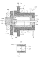
図1及び図2は、本発明の着座重量測定器の実施例1を示し、図1(A)は着座重量測定器の縦断面図、図1(B)は重量検出部の縦断面図、図2は着座重量測定器の要部の斜視図である。 1 and 2 show a first embodiment of a seating weight measuring device according to the present invention, FIG. 1 (A) is a longitudinal sectional view of the sitting weight measuring device, and FIG. 1 (B) is a longitudinal sectional view of a weight detecting unit, FIG. 2 is a perspective view of a main part of the seating weight measuring device.
図において、着座重量測定器11は、座席レール12にナット13を介して固定される支持体14と、この支持体14を包囲する筐体15とを備えている。
In the figure, the seating weight measuring instrument 11 includes a
この支持体14は、座席レール12に形成された孔12aの開口形状と略一致してラジアル方向の回転を規制するように面取りされた断面略小判形状の固定軸14aが一端から突出されている。この固定軸14aの外周にはナット13と螺合するためのネジ溝が形成されている。また、支持体14の他端にはケーブル貫通孔14bを形成した突出部14cが形成されている。さらに、支持体14には、軸線と直交する水平軸線上(紙面奥行き方向)に延びる凹部(保持体対向部)14dが形成されていると共に、ケーブル貫通孔14cと凹部14dとの間を中空とした空間部14eとが形成されている。尚、中空部14eは、例えばフライス加工によって形成され、座席力Fによる負荷(荷重)を筐体15を介して受けた際の応力集中(切欠き効果)を減少させるために、内壁面の隣接する壁面管を丸みのある湾曲した壁面で連続させている。
The
筐体15は、車両用シート本体(全体図省略)の一部を構成するアーム16にナット17を介して固定されている。また、筐体15は、固定軸14aを除いた他端側を離間状態で包囲している。この際、筐体15は、突出部14cを開口15aで保持している。
The
一方、ケーブル貫通孔14bには、保形性を有するケーブル(保持体)18の中途部を保持している。このケーブル18の先端には、凹部14dに設けられてケーブル貫通穴14c側に開放する断面コ字形状の磁気発生手段(この例では永久磁石、以下同様)19に臨む検出体20が設けられている。
On the other hand, the middle part of the cable (holding body) 18 having shape retention is held in the cable through
永久磁石19は、図1(B)に示すように、車体の上下方向で検出体20と所定間隔を存して対向しており、車体水平方向に開放している。なお、必ずしも開放構造でなくても、車体水平方向における検出体20への対向距離が車体上下方向における対向距離よりも十分に大きくされていれば足りる。
As shown in FIG. 1B, the
検出体20は、内部に磁気式のセンサー(磁気検出手段)を有しており、このセンサーがホールICとして形成されている。尚、常時は、検出体20は永久磁石19に対して車体上下方向中間に位置している。
The
このような構成において、車両用シート本体に着座者がいた場合、その着座者の体重に相当する測定すべき座席力Fがアーム16及び筐体15を介して支持体14の突出部14cに伝達される。この結果、支持体14は、座席レール12内に片持ち式に支承されていることに基づき変形するため、この変形量を永久磁石19を検出体20との相対位置変位量とで測定することにより着座者の体重を測定する。
In such a configuration, when there is a seated person on the vehicle seat body, a seating force F to be measured corresponding to the weight of the seated person is transmitted to the protruding portion 14c of the
すなわち、支持体14が変形すると、ケーブル18がケーブル貫通穴14bを支点として傾斜し、検出体20と永久磁石19との相対位置が変化する。永久磁石19の磁束線は、その磁界強度が狭くなった領域で増大する。従って、その磁界強度の変化を検出体20のセンサーによって検出することによって、着座者の体重を測定することができる。
That is, when the
このように、永久磁石19が水平面内で開放しているため、検出体20は車体上下方向にのみ検出感度を備えていることとなり、車体水平方向の不測な変位に起因する誤測定を防止することができる。
As described above, since the
ところで、永久磁石19は、重量測定のためには検出体20が車体上方に変位した際の変位量を検出体20で検出することができればよいことから、例えば、図3及び図4に示すように、車体上方にのみ配置した永久磁石29としてもよい。また、永久磁石19は、図5に示すように、支持体14に埋設してもよい。
By the way, the
さらに、図6に示すように、前述の図9と同様に、永久磁石19と検出体20との両方がケーブル18の先端に設けられ、検出体20内のセンサーにて、保持体対向部としての凹部14dとの上下方向対向距離の変化に応じた磁界強度の変化を検出するようにしてもよい。これらの場合も同様の効果を得る。
Further, as shown in FIG. 6, both the
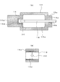
図7及び図8は、本発明の着座重量測定器の実施例2を示し、図7(A)は着座重量測定器の縦断面図、図7(B)は重量検出部の縦断面図であり、図8は着座重量測定器の要部の斜視図である。
7 and 8
図において、着座重量測定器21は、座席レール12にナット13を介して固定される支持体14と、この支持体14を包囲する筐体15とを備えている。
In the figure, the seating weight measuring instrument 21 includes a
支持体14は、端部14A,14Bと、略平板状の上面部14C及び下面部14Dとから構成される分割構造(端部14A,14Bと上面部14C,14Dとは溶接やリベット等の適宜の固定手段にて固定)であり、このような側方開放構造によって、車体上下方向における剛性が車体水平方向における剛性よりも小さくなるように構成されている。
The
支持体端部14Aは、座席レール12に形成された孔12aの開口形状と略一致してラジアル方向の回転を規制するように面取りされた断面略小判形状の固定軸14aが一端から突出されている。この固定軸14aの外周にはナット13と螺合するためのネジ溝が形成されている。また、支持体端部14Bにはケーブル貫通孔14bを形成した突出部14cが形成されている。さらに、支持体端部14Aには、軸線と直交する水平軸線上(紙面奥行き方向)に延びる凹部(保持体対向部)14dが形成され、支持体端部14A及び支持体端部14Bとの間には空間部14eが形成されている。
The support body end portion 14A has a fixed shaft 14a having a substantially oval cross section that is chamfered so as to substantially coincide with the opening shape of the hole 12a formed in the seat rail 12 and restricts rotation in the radial direction, and protrudes from one end. Yes. A thread groove for screwing with the
筐体15については、上記実施例1とほぼ同様の構造であるので詳細な説明を省略する。
The
一方、支持体端部14Bのケーブル貫通孔14bには、保形性を有するケーブル18の中途部を保持している。このケーブル18の先端には、凹部14dに設けられてケーブル貫通穴14c側に開放する断面コ字形状の磁気発生手段(この例では永久磁石)19に臨む検出体20が設けられている。
On the other hand, the middle portion of the
永久磁石19は、上記実施例1と同様、少なくとも、車体水平方向における検出体20への対向距離が車体上下方向における対向距離よりも十分に大きくされている。検出体20についても上記実施例1と同様である。
As in the first embodiment, at least the facing distance to the
上記実施例2の構成において、車両用シート本体に着座者がいた場合、その着座者の体重に相当する測定すべき座席力Fが上記実施例1と同様に支持体端部14Bの突出部14cに伝達される。この結果、支持体14は、座席レール12内に片持ち式に支承されていることに基づき変形するため、この変形量を永久磁石19を検出体20との相対位置変位量とで測定することにより着座者の体重を測定する。
In the configuration of the second embodiment, when there is a seated person on the vehicle seat body, the seating force F to be measured corresponding to the weight of the seated person is the protruding portion 14c of the support end 14B as in the first embodiment. Is transmitted to. As a result, since the
すなわち、支持体14が変形すると、ケーブル18がケーブル貫通穴14bを支点として傾斜し、支持体端部14Aの位置が座席レール12に対して固定であることから、検出体20と永久磁石19との相対位置が変化する。永久磁石19の磁束線は、その磁界強度が狭くなった領域で増大する。従って、その磁界強度の変化を検出体20のセンサーによって検出することによって、着座者の体重を測定することができる。
That is, when the
このとき特に、支持体14の車体上下方向における剛性が車体水平方向における剛性よりも小さくなるように構成され、支持体14は特に上下方向により変形しやすく(たわみやすく)なっている。そしてさらに、永久磁石19が水平面内で開放し、検出体20は車体上下方向にのみ検出感度を備えている。これらにより、車体水平方向の不測な変位に起因する誤測定を防止することができる。また、本実施例では、上記のような分割構造により支持体14を加工しやすくなる、という効果もある。
At this time, in particular, the rigidity of the
なお、上記実施例2において、従来よりも車体上下方向における検出精度を向上するという本発明本来の効果を得る限りにおいては、永久磁石19は上記のように車体水平方向に開放したり、車体上下方向における検出体20への対向距離を車体水平方向よりも小さくせず、前述の図9(B)に示したように上下方向・水平方向対向距離を略同一としてもよい。この場合でも、上記支持体14の剛性の差異により、少なくとも従来よりは車体上下方向における検出精度を向上することができる。
In the second embodiment, the
さらに、上記実施例2においても、前述の図6の変形例と同様、永久磁石19と検出体20との両方がケーブル18の先端に設けられ、検出体20内のセンサーにて、保持体対向部としての凹部14dとの上下方向対向距離の変化に応じた磁界強度の変化を検出するようにしてもよい。これらの場合も同様の効果を得る。
Further, also in the second embodiment, both the
11…着座重量測定器
12…座席レール
13…ナット
14…支持体
15…筐体
16…アーム
17…ナット
18…保持体
19…永久磁石
20…検出体
DESCRIPTION OF SYMBOLS 11 ... Seating weight measuring device 12 ...
Claims (8)
前記支持体の他方側に中途部が保持された保形性を有する保持体と、
前記支持体の変位を検出するために、前記保持体の先端部に対向するように前記支持体に設けられ、車体上下方向における前記保持体先端部への対向距離が車体水平方向における前記保持体先端部への対向距離よりも小さくされた保持体対向部と、
前記保持体の先端に設けられた磁気検出手段とを備え、
車両用シート側からの荷重量に応じた前記支持体の変位に連動する、前記車体上下方向における前記対向距離の変化に伴う磁界強度の変化に基づいて車両用シート側からの荷重量を測定することを特徴とする着座重量測定器。 A support body whose one side is fixed relative to the vehicle body and whose other side is displaced according to the amount of load from the vehicle seat side;
A holding body having a shape-retaining property in which a midway part is held on the other side of the support;
In order to detect displacement of the support body, the support body is provided so as to face the front end portion of the holding body, and the distance to the front end portion of the support body in the vertical direction of the vehicle body is the holding body in the vehicle body horizontal direction A holding body facing portion that is made smaller than the facing distance to the tip portion;
Magnetic detection means provided at the tip of the holding body,
The load amount from the vehicle seat side is measured based on the change in the magnetic field strength accompanying the change in the facing distance in the vertical direction of the vehicle body in conjunction with the displacement of the support according to the load amount from the vehicle seat side. A seating weight measuring device characterized by that.
前記磁気検出手段は、前記第1磁気発生手段から発生され前記車体上下方向における前記対向距離に応じて変化する磁界強度を検出することを特徴とする請求項1に記載の着座重量測定器。 The holding body facing portion includes first magnetism generating means,
The seating weight measuring apparatus according to claim 1, wherein the magnetic detection means detects a magnetic field intensity generated from the first magnetic generation means and changing according to the facing distance in the vertical direction of the vehicle body.
前記磁気検出手段は、前記第2磁気発生手段から発生され前記車体上下方向における前記対向距離に応じて変化する磁界強度を検出することを特徴とする請求項1に記載の着座重量測定器。 A second magnetism generating means provided at the tip of the holding body;
The seating weight measuring apparatus according to claim 1, wherein the magnetic detection means detects a magnetic field intensity generated from the second magnetic generation means and changing according to the facing distance in the vertical direction of the vehicle body.
前記支持体の他方側に中途部が保持された保形性を有する保持体と、
前記支持体の変位を検出するために、前記保持体の先端部に対向するように前記支持体に設けられた保持体対向部と、
前記保持体の先端に設けられた磁気検出手段とを備え、
車両用シート側からの荷重量に応じた前記支持体の変位に連動する、前記保持体対向部の前記保持体先端部への対向距離の変化に伴う磁界強度に基づいて車両用シート側からの荷重量を測定することを特徴とする着座重量測定器。 A support body configured such that rigidity in the vertical direction of the vehicle body is smaller than rigidity in the horizontal direction of the vehicle body, one side is fixed at a relative position with respect to the vehicle body, and the other side is displaced according to a load amount from the vehicle seat side;
A holding body having a shape-retaining property in which a midway part is held on the other side of the support;
In order to detect the displacement of the support body, a holding body facing portion provided on the support body so as to face the front end portion of the holding body;
Magnetic detection means provided at the tip of the holding body,
Based on the magnetic field strength associated with the change in the facing distance of the holding body facing portion to the tip of the holding body, which is interlocked with the displacement of the support body according to the load amount from the vehicle seat side, from the vehicle seat side. A seating weight measuring device characterized by measuring a load amount.
前記磁気検出手段は、前記第3磁気発生手段から発生され前記対向距離に応じて変化する磁界強度を検出することを特徴とする請求項6に記載の着座重量測定器。 The holding member facing portion includes third magnetism generating means,
The seating weight measuring device according to claim 6, wherein the magnetic detection unit detects a magnetic field intensity generated from the third magnetic generation unit and changing according to the facing distance.
前記磁気検出手段は、前記第4磁気発生手段から発生され前記対向距離に応じて変化する磁界強度を検出することを特徴とする請求項6に記載の着座重量測定器。 Comprising a fourth magnetism generating means provided at the tip of the holder,
The seating weight measuring device according to claim 6, wherein the magnetic detection unit detects a magnetic field intensity generated from the fourth magnetic generation unit and changing according to the facing distance.
Priority Applications (4)
| Application Number | Priority Date | Filing Date | Title |
|---|---|---|---|
| JP2004154153A JP2005337770A (en) | 2004-05-25 | 2004-05-25 | Seating weight measuring apparatus |
| US11/132,218 US20050264046A1 (en) | 2004-05-25 | 2005-05-19 | Seat weight measuring apparatus |
| CNA2005100738011A CN1702439A (en) | 2004-05-25 | 2005-05-24 | Seat weight measuring apparatus |
| EP05011403A EP1600750A1 (en) | 2004-05-25 | 2005-05-25 | Seat weight measuring apparatus |
Applications Claiming Priority (1)
| Application Number | Priority Date | Filing Date | Title |
|---|---|---|---|
| JP2004154153A JP2005337770A (en) | 2004-05-25 | 2004-05-25 | Seating weight measuring apparatus |
Publications (1)
| Publication Number | Publication Date |
|---|---|
| JP2005337770A true JP2005337770A (en) | 2005-12-08 |
Family
ID=34936963
Family Applications (1)
| Application Number | Title | Priority Date | Filing Date |
|---|---|---|---|
| JP2004154153A Withdrawn JP2005337770A (en) | 2004-05-25 | 2004-05-25 | Seating weight measuring apparatus |
Country Status (4)
| Country | Link |
|---|---|
| US (1) | US20050264046A1 (en) |
| EP (1) | EP1600750A1 (en) |
| JP (1) | JP2005337770A (en) |
| CN (1) | CN1702439A (en) |
Families Citing this family (4)
| Publication number | Priority date | Publication date | Assignee | Title |
|---|---|---|---|---|
| CN102798448B (en) * | 2012-09-06 | 2015-02-04 | 上海新世纪机器人有限公司 | Online load detection device for self-balancing two-wheel vehicle |
| CN102963274A (en) * | 2012-10-25 | 2013-03-13 | 浙江吉利汽车研究院有限公司杭州分公司 | Adaptive automobile seat system and seat adjustment method |
| US11719557B2 (en) | 2019-12-24 | 2023-08-08 | Joyson Safety Systems Acquisition Llc | Apparatus and method of producing a sensing substrate |
| CN114018381B (en) * | 2021-12-07 | 2024-02-27 | 南京智鹤电子科技有限公司 | Vehicle load monitoring system and monitoring method thereof |
Family Cites Families (10)
| Publication number | Priority date | Publication date | Assignee | Title |
|---|---|---|---|---|
| EP0713637B1 (en) * | 1994-11-24 | 2000-12-20 | NEW HOLLAND ITALIA S.p.A. | Draft force sensor apparatus |
| US5580084A (en) * | 1995-09-12 | 1996-12-03 | Artistic Analytical Methods, Inc. | System and method for controlling vehicle safety device |
| US5864295A (en) * | 1996-03-21 | 1999-01-26 | Trw Inc. | Apparatus for sensing occupant weight in an actuatable restraint system |
| US6087598A (en) * | 1999-02-03 | 2000-07-11 | Trw Inc. | Weight sensing apparatus for vehicle seat |
| DE10035483B4 (en) * | 2000-07-21 | 2005-07-21 | Sartorius Hamburg Gmbh | Force transducer for a vehicle seat |
| JP2002174556A (en) * | 2000-12-08 | 2002-06-21 | Mitsubishi Electric Corp | Crew-detecting device |
| CN1265178C (en) * | 2001-07-31 | 2006-07-19 | 古河电气工业株式会社 | Weight sensing device |
| DE10216723A1 (en) * | 2002-04-16 | 2003-10-30 | Bosch Gmbh Robert | Motor vehicle seat weight sensor comprises a support body that moves relative to its mounting and in so doing causes the magnetic field of a permanent magnet mounted within in to change so that it can be detected by a field sensor |
| DE10229023A1 (en) * | 2002-06-28 | 2004-01-29 | Robert Bosch Gmbh | force sensor |
| DE10252224A1 (en) * | 2002-11-11 | 2004-05-27 | Robert Bosch Gmbh | Motor vehicle seat weight sensor, comprises a permanent magnet with a ferromagnetic housing that is displaced by a downward force on the seat such that the field detected by a magnetic field sensor changes |
-
2004
- 2004-05-25 JP JP2004154153A patent/JP2005337770A/en not_active Withdrawn
-
2005
- 2005-05-19 US US11/132,218 patent/US20050264046A1/en not_active Abandoned
- 2005-05-24 CN CNA2005100738011A patent/CN1702439A/en active Pending
- 2005-05-25 EP EP05011403A patent/EP1600750A1/en not_active Withdrawn
Also Published As
| Publication number | Publication date |
|---|---|
| CN1702439A (en) | 2005-11-30 |
| EP1600750A1 (en) | 2005-11-30 |
| US20050264046A1 (en) | 2005-12-01 |
Similar Documents
| Publication | Publication Date | Title |
|---|---|---|
| JP4399216B2 (en) | Force sensor | |
| JP2003329519A (en) | Force measuring apparatus | |
| JP2009048926A (en) | Proximity sensor | |
| JP2005300247A (en) | Displacement sensor | |
| JP4955286B2 (en) | External force detection device | |
| JP2005337770A (en) | Seating weight measuring apparatus | |
| US7069796B2 (en) | Dynamometer, particularly for determining the seating weight in a motor vehicle | |
| JP6934006B2 (en) | Detection of seatbelt sensor movement | |
| JP6986919B2 (en) | buckle | |
| JP2007057425A (en) | Seat load detector | |
| JP6604857B2 (en) | Torque sensor, torque sensor unit and penetration tester | |
| JP2007168776A (en) | Force sensor device arranged on two-wheeler | |
| JP2003222561A (en) | Tension detector | |
| JP2011182826A (en) | Seatbelt displacement detection device | |
| JP2005017008A (en) | Apparatus for detecting tensile force | |
| JP2015131548A (en) | Seating state determination device and air bag system | |
| EP1650564A4 (en) | Mechanochemical type sensor | |
| JP2005098826A (en) | Vortex flowmeter | |
| JP2002206976A (en) | Seatbelt tension measuring apparatus | |
| JP4595529B2 (en) | Seat load detection device | |
| JP2005335862A (en) | Chain inspecting device | |
| JP2007285991A (en) | Load detecting device | |
| JP2005271882A (en) | Seat displacement measurement instrument, and seat device for automobile | |
| JP4077761B2 (en) | Tension detector | |
| JP2005271884A (en) | Occupant detector |
Legal Events
| Date | Code | Title | Description |
|---|---|---|---|
| A711 | Notification of change in applicant |
Free format text: JAPANESE INTERMEDIATE CODE: A712 Effective date: 20060318 |
|
| A521 | Written amendment |
Free format text: JAPANESE INTERMEDIATE CODE: A523 Effective date: 20060629 |
|
| RD02 | Notification of acceptance of power of attorney |
Free format text: JAPANESE INTERMEDIATE CODE: A7422 Effective date: 20061211 |
|
| A300 | Application deemed to be withdrawn because no request for examination was validly filed |
Free format text: JAPANESE INTERMEDIATE CODE: A300 Effective date: 20070807 |