Field of the Invention.
This invention relates generally to portable
apparatus for freezing the liquid contents of pipes
for working on the pipe, and to the more particular
field of portable pipe freezers that use a
refrigerant cycle for cooling the pipe.
Background of the Invention.
Pipe freezers are used in repairing or replacing
pipe sections or repairing or adding fittings. When
there is no convenient shut-off valve, the effect of
blocking flow in the pipe can be achieved by
freezing the water in a section of the pipe. The
frozen section acts as an ice plug that blocks flow.
Some pipe freezer devices use frozen CO2 (dry ice)
for the heat transfer to freeze the section of pipe.
This invention however, relates to devices that use
a refrigerant in a refrigeration cycle for the heat
transfer. Such devices are described, for example,
in U. S. patent 5,548,965 and its counterparts DE
196 17 619.0 and GB 2,301,661. The same patent
describes an evaporator head with multiple channels
sized to fit various standard pipe diameters. Two
evaporator heads are connected to a portable
condenser/compressor unit by flexible coaxial tubes
that cycle refrigerant to and from the evaporation
chambers.
This invention improves upon the pipe freezer of
U.S. Patent 5,548,965 by structural differences that
make it easier to install the evaporator heads in
some situations; specifically the use of
interchangeable adapters that slide onto the
evaporator chambers to adapt the head for pipes of
different diameters. The invention further adds
internal structural differences that improve the
distribution and flow path of the refrigerant along
the pipe section, and thus improve the evaporation
heat exchange.
Summary of the Invention.
The invention is in an apparatus for freezing the
contents of a pipe through the use of a
refrigeration cycle. The apparatus includes a
portable condenser/compressor unit and a pair of
flexible coaxial hoses connected to an evaporation
chamber. A set of interchangeable adapters, each
configured with one or more nearly semicircular
channels conforming to a standard pipe diameter are
used to place the evaporation chamber along and in
heat transfer conduction with a section of a pipe.
The adapters are configured to hold the evaporation
chamber in a position such that the length axis of
the chamber is aligned parallel to the axis of the
pipe. The evaporation chamber has its coupling for
the refrigerant hose located along its length
dimension. The coupling orients the hose such that
the hose is generally perpendicular to the length
axis of the evaporation chamber. This angle of
connection into the adapter makes it easier to
install the evaporator head to a pipe when the pipe
is close to a wall or structure that interferes with
the hose being aligned parallel to the pipe.
Inside the evaporation chamber, a baffle may be
placed between the outlet of the inner tube of the
hose and the return to the outer tube. The baffle
forces refrigerant sprayed out of the inner tube to
migrate from essentially the entry point of the
chamber to an end wall and then back toward the
entry point before entering the outer tube. This
long migration path allows more efficient
evaporation in the chamber and thus more efficient
heat exchange.
In a preferred embodiment, the evaporation chamber
is in the shape of a right cylinder closed by a pair
of end plates. A set of interchangeable adapters
has on each adapter a channel of greater than
semicircular arc and a radius just slightly larger
than that of the cylindrical chamber to provide a
conformal "slide-on" fit over the cylindrical
chamber. The channel defines an open slot that
allows the adapter to slide past the hose coupling.
The channel is preferably be less than about 330°
arc so that the slot is large enough to allow some
rotational movement of the chamber within the
adapter channel to facilitate connection to the
pipe.
The evaporation chamber is constructed of a heat
conductive metal, preferably aluminum. In a
preferred embodiment, the evaporation chamber is
protected from dents and scratches by installing
over it a replaceable open cylindrical sleeve. When
the sleeve is used, the adapters are sized to
provide a slide-on conformal fit over the sleeve.
Brief Description of the Drawings.
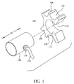
Figure 1 is a perspective view of a cylindrical
evaporator chamber and one of a set of adapters for
different standard diameters of pipe.
Figure 2 is a profile view of another adapter.
Figure 3 is a profile view of another adapter.
Figure 4 is a section view of an evaporator chamber
and adapter on a pipe.
Figure 5 is a schematic view of an evaporator in
section connected to a condenser/compressor unit to
show flow path of refrigerant.
Figure 6 is a section view of a cylindrical
evaporation chamber with a preferred configuration
of baffle.
Figure 7 is a partially exploded view of an
evaporation chamber with a replaceable protective
sleeve.
Figure 8 is a profile view of a rectangular
evaporation chamber and an associated adapter.
Figure 9 is a schematic view of the prior art
portable pipe freezer of U. S. Patent 5,548,965.
Detailed Description of Several Embodiments of the
Invention.
The invention is in improvements to a portable pipe
freezer apparatus as disclosed in U.S. patent
5,548,965. The description of the preferred
embodiments of that patent are adopted herein by
reference so that it will not be necessary to repeat
common elements. In brief description, however,
Figure 9 (reproduced from U. S. 5,548,965) shows the
basic elements of that prior portable pipe freezer
apparatus.
Referring to Figure 9, the pipe freezer apparatus
system (10) is installed on a pipe (12) to freeze
the water (14) inside a section of pipe to form an
ice plug. The piper freezer includes a portable
condenser/compressor unit (16) that has a compressor
(18), a pair of condensers (20), and a fan (22).
The condenser /compressor unit is connected to a
pair of evaporators (24 and 26) by flexible coaxial
hoses (28and 30, respectively). The coaxial hoses
have an inner tube (32) and an outer tube (34). The
inner tube delivers high-pressure liquid refrigerant
to an evaporation chamber and the outer tube returns
refrigerant vapor from the evaporation chamber to
the condenser/compressor unit.
In the well-known refrigeration cycle, liquid
refrigerant (36) under high pressure enters through
the inner tube (32) into an inner chamber (38) of
the evaporators. The inner tube extends well into
the chamber and acts as a metering device to spray
the liquid refrigerant into the low-pressure inner
chamber of the evaporators. As the refrigerant
evaporates, it absorbs heat from the evaporator (24)
and by conduction heat exchange from the adjacent
pipe and the water inside the pipe. The refrigerant
vapor is drawn from the evaporator through the outer
tube (34) by suction and returned into the
compressor 18, which raises the pressure of the
vapor. The high pressure vapor passes through a
condenser, in which the vapor is exposed to a large
cooling surface area from which heat is convected by
the fan (22). The refrigerant (36) is cooled to the
condensation temperature, releases its heat of
condensation and changes phase back into a liquid at
high pressure to complete the cycle.
This invention changes the configuration of the
evaporators. As shown in Figure 1, the evaporation
chamber is inside a metal cylinder 100 or evaporator
head. The evaporator head is provided with a set of
interchangeable adapters to fit pipes of different
standard diameters. The adapter 102 in Figure 1 has
different-sized, nearly semi-circular channels (104,
106, 108 and 110) for a conforming fit along
relatively small (e.g., 15mm, 18mm, 22mm and 28 mm)
diameter pipes. It would be sufficient, however, to
provide a different adapter for each pipe diameter.
The adapter 102 also has a greater than semicircular
channel 112 having a radius sufficient to make a
slide-on conforming fit over the outer surface of
the evaporator head to receive the evaporator head
and to hold the evaporator chamber in a position
such that the length axis ("D" in Figure 1) is
aligned parallel to the axis of a pipe placed in any
of the semicircular channels.
The coaxial hose (114) does not enter along the end
of the cylinder, but rather enters through a hose
coupling (116) that is located approximately midway
along the length (D) of the cylinder. The hose
coupling directs the inner tube of the hose
generally perpendicular to the length axis of the
evaporation chamber. The hose could be made to
enter the chamber at a more acute angle, although
there is no apparent advantage to do so.
The channel 112 on the adapter has a arc of greater
than 180 degrees, but preferably not more than about
330 degrees, so that the cylindrical evaporator head
can slide into the channel with the hose and hose
coupling in the slot 112 that is left open. It is
most preferable to have the slot extend even further
to permit the cylinder to rotate inside the coupling
through about 45 degrees so that the hose can be
positioned according to the space and obstacles
around the pipe. The connection to the evaporator
in a direction generally perpendicular to the pipe
permits the freezer unit to be used in more confined
space than orienting the hoses along the axis of the
pipe, as in the prior pipe freezer.
Other adapters in the set are shown in Figures 2 and
3. The adapter (120) of Figure 2 has two nearly
semi-circular channels (124 and 122) conforming to
the outer diameter of intermediate sized pipes (e.
g. 35mm and 42mm, or 48mm and 60mm)). The adapter
(128) of Figure 3 has a single nearly semi-circular
channel (130) for a relatively large pipe (e.g. 73
mm or higher.). The greater than semi-circular
channel (126 and 132) for the evaporator head is the
same as the channel (112) on the adapter 102 of
Figure 1.
Referring now to Figure 4, when the adapter (102) is
placed on a water pipe (120), the hose coupling
directs the hose in a direction essentially at right
angle to the axis of the pipe. The inner tube (122)
of the hose projects through the coupling to near
the opposite inner wall of the cylinder to spray the
liquid refrigerant against the wall. As the
refrigerant evaporates, the vapor is drawn back into
the coupling to the outer tube of the hose. Since
the coupling orients the inner tube essentially
perpendicular to the length axis of the chamber, the
distance from the end of the inner tube back into
the coupling is not as great as when the inner tube
is aligned with the length axis. This situation may
result in less efficient heat transfer, as some
liquid refrigerant may be drawn back into the outer
hose and evaporate on return to the compressor
rather than in the chamber.
To make the refrigerant evaporation in the chamber
more efficient, a metal baffle plate (124) is placed
in the evaporator head, as shown in Figure 5. The
baffle plate preferably is located in a chord of the
cylindrical chamber near the hose coupling and
extends toward and nearly to the end walls of the
chamber. The baffle plate (124) may be a flat plate
extending along the length of the chamber and
terminate near the end plates, or as in Figures Sand
6, may then extend along the end plates of the
chamber.
The inner tube (122) of the refrigerant hose extends
through the baffle plate. Thus, refrigerant sprayed
from the inner tube (122) must migrate to the ends
of the chamber to pass around the plate (124) and
return to the midpoint of the chamber to be pulled
into the coupling for return to the
compressor/condenser (128) in the outer tube of the
hose (126). This longer path makes more evaporation
take place in the chamber and promotes more
efficient heat exchange.
Figures 5 and 6 show a preferred configuration of
baffle. The baffle (130) is saddle-shaped with a
long flat top section (132) and two end sections
(134) close to and essentially parallel to the end
walls (136) of the cylinder. This creates a large
evaporation space inside the baffle and forces the
refrigerant to migrate essentially along the
perimeter of the chamber before re-entering the hose
coupling (116).
Figure 7 shows another preferred construction of a
cylindrical evaporation chamber. The chamber, as
described in previous embodiments, is formed as a
hollow right cylinder (138) closed at both ends by
end plates (136). The cylinder and plates are
formed from a heat conductive metal, preferably
aluminum. To obtain good heat conduction between
the chamber and the adapter, the surface of the
cylinder should make a tight conforming fit into the
adapter. This smooth fit would be lost if the
cylinder became dented or scratched, as softer
metals are prone to become in a working environment.
To protect the valuable evaporation chamber, it is
preferred to install over it a replaceable
protective sleeve (140), as shown in Figure 7. The
sleeve is also made of a heat conductive metal,
again preferably aluminum. The sleeve has a slot
opening to allow the sleeve to slide past the hose
coupling onto the cylinder. The adapters are sized
to made a tight conformal fit with the sleeve. If
the sleeve becomes dented or scratched, it can be
replaced at much less cost than the evaporation
chamber.
Figure 8 shows an alternative shape of evaporation
chamber. In the embodiment, the chamber (150) is
rectangular in cross section, with its length
dimension directed into the paper. The adapter
(152) has a rectangular channel for a conformal fit
around three sides of the chamber. The rectangular
chamber is slide into the adapter, and a bracket
(154) is placed over it and held to the adapter by
thumbscrews (156) in threaded bores of the adapter.
Otherwise, the evaporator is similar to the
cylindrical evaporator in that the hose coupling is
located approximately midway along the evaporator's
length dimension and is oriented perpendicular to
the length axis of the chamber. A baffle is
preferably located in the chamber between the outlet
of the inner tube of the hose and the return to the
outer tube to force refrigerant sprayed out of the
inner tube to migrate from essentially the midway
point of the chamber to an end wall and then back
toward the midway point before entering the outer
tube.
Other shapes of evaporation chamber could also be
used in accordance with the invention. For example,
the exterior of the chamber could include flat
sides, such as a hexagonal or octagonal cylinder,
and the adapters would be correspondingly configured
to slide-on over the hexagonal or octagonal
exterior.