EP1281920A2 - Rohrgefriergerät mit Schnellanschlussrohrpassteilen - Google Patents
Rohrgefriergerät mit Schnellanschlussrohrpassteilen Download PDFInfo
- Publication number
- EP1281920A2 EP1281920A2 EP02253044A EP02253044A EP1281920A2 EP 1281920 A2 EP1281920 A2 EP 1281920A2 EP 02253044 A EP02253044 A EP 02253044A EP 02253044 A EP02253044 A EP 02253044A EP 1281920 A2 EP1281920 A2 EP 1281920A2
- Authority
- EP
- European Patent Office
- Prior art keywords
- chamber
- pipe
- adapter
- hose
- evaporation chamber
- Prior art date
- Legal status (The legal status is an assumption and is not a legal conclusion. Google has not performed a legal analysis and makes no representation as to the accuracy of the status listed.)
- Withdrawn
Links
- 230000008020 evaporation Effects 0.000 claims abstract description 44
- 238000001704 evaporation Methods 0.000 claims abstract description 44
- 239000003507 refrigerant Substances 0.000 claims abstract description 30
- 230000008878 coupling Effects 0.000 claims abstract description 25
- 238000010168 coupling process Methods 0.000 claims abstract description 25
- 238000005859 coupling reaction Methods 0.000 claims abstract description 25
- 230000001681 protective effect Effects 0.000 claims abstract description 4
- 229910052751 metal Inorganic materials 0.000 claims description 9
- 239000002184 metal Substances 0.000 claims description 9
- 239000007788 liquid Substances 0.000 claims description 8
- 238000007710 freezing Methods 0.000 claims description 4
- 230000008014 freezing Effects 0.000 claims description 4
- 238000005057 refrigeration Methods 0.000 claims description 4
- 238000013459 approach Methods 0.000 claims 1
- 230000001351 cycling effect Effects 0.000 claims 1
- XLYOFNOQVPJJNP-UHFFFAOYSA-N water Substances O XLYOFNOQVPJJNP-UHFFFAOYSA-N 0.000 description 4
- 229910052782 aluminium Inorganic materials 0.000 description 3
- XAGFODPZIPBFFR-UHFFFAOYSA-N aluminium Chemical compound [Al] XAGFODPZIPBFFR-UHFFFAOYSA-N 0.000 description 3
- CURLTUGMZLYLDI-UHFFFAOYSA-N Carbon dioxide Chemical compound O=C=O CURLTUGMZLYLDI-UHFFFAOYSA-N 0.000 description 2
- 230000005494 condensation Effects 0.000 description 2
- 238000009833 condensation Methods 0.000 description 2
- 238000001816 cooling Methods 0.000 description 2
- 239000007921 spray Substances 0.000 description 2
- 241000009298 Trigla lyra Species 0.000 description 1
- 230000001154 acute effect Effects 0.000 description 1
- 230000000903 blocking effect Effects 0.000 description 1
- 235000011089 carbon dioxide Nutrition 0.000 description 1
- 238000010276 construction Methods 0.000 description 1
- 230000000694 effects Effects 0.000 description 1
- 150000002739 metals Chemical class 0.000 description 1
- 230000005012 migration Effects 0.000 description 1
- 238000013508 migration Methods 0.000 description 1
- 239000004576 sand Substances 0.000 description 1
Images


Classifications
-
- F—MECHANICAL ENGINEERING; LIGHTING; HEATING; WEAPONS; BLASTING
- F25—REFRIGERATION OR COOLING; COMBINED HEATING AND REFRIGERATION SYSTEMS; HEAT PUMP SYSTEMS; MANUFACTURE OR STORAGE OF ICE; LIQUEFACTION SOLIDIFICATION OF GASES
- F25D—REFRIGERATORS; COLD ROOMS; ICE-BOXES; COOLING OR FREEZING APPARATUS NOT OTHERWISE PROVIDED FOR
- F25D15/00—Devices not covered by group F25D11/00 or F25D13/00, e.g. non-self-contained movable devices
-
- F—MECHANICAL ENGINEERING; LIGHTING; HEATING; WEAPONS; BLASTING
- F16—ENGINEERING ELEMENTS AND UNITS; GENERAL MEASURES FOR PRODUCING AND MAINTAINING EFFECTIVE FUNCTIONING OF MACHINES OR INSTALLATIONS; THERMAL INSULATION IN GENERAL
- F16L—PIPES; JOINTS OR FITTINGS FOR PIPES; SUPPORTS FOR PIPES, CABLES OR PROTECTIVE TUBING; MEANS FOR THERMAL INSULATION IN GENERAL
- F16L55/00—Devices or appurtenances for use in, or in connection with, pipes or pipe systems
- F16L55/10—Means for stopping flow in pipes or hoses
- F16L55/103—Means for stopping flow in pipes or hoses by temporarily freezing liquid sections in the pipe
-
- F—MECHANICAL ENGINEERING; LIGHTING; HEATING; WEAPONS; BLASTING
- F25—REFRIGERATION OR COOLING; COMBINED HEATING AND REFRIGERATION SYSTEMS; HEAT PUMP SYSTEMS; MANUFACTURE OR STORAGE OF ICE; LIQUEFACTION SOLIDIFICATION OF GASES
- F25B—REFRIGERATION MACHINES, PLANTS OR SYSTEMS; COMBINED HEATING AND REFRIGERATION SYSTEMS; HEAT PUMP SYSTEMS
- F25B39/00—Evaporators; Condensers
- F25B39/02—Evaporators
-
- F—MECHANICAL ENGINEERING; LIGHTING; HEATING; WEAPONS; BLASTING
- F28—HEAT EXCHANGE IN GENERAL
- F28F—DETAILS OF HEAT-EXCHANGE AND HEAT-TRANSFER APPARATUS, OF GENERAL APPLICATION
- F28F9/00—Casings; Header boxes; Auxiliary supports for elements; Auxiliary members within casings
- F28F9/02—Header boxes; End plates
- F28F9/0246—Arrangements for connecting header boxes with flow lines
- F28F9/0256—Arrangements for coupling connectors with flow lines
- F28F9/0258—Arrangements for coupling connectors with flow lines of quick acting type, e.g. with snap action
Definitions
- This invention relates generally to portable apparatus for freezing the liquid contents of pipes for working on the pipe, and to the more particular field of portable pipe freezers that use a refrigerant cycle for cooling the pipe.
- Pipe freezers are used in repairing or replacing pipe sections or repairing or adding fittings.
- the effect of blocking flow in the pipe can be achieved by freezing the water in a section of the pipe.
- the frozen section acts as an ice plug that blocks flow.
- Some pipe freezer devices use frozen CO 2 (dry ice) for the heat transfer to freeze the section of pipe.
- This invention relates to devices that use a refrigerant in a refrigeration cycle for the heat transfer.
- Such devices are described, for example, in U. S. patent 5,548,965 and its counterparts DE 196 17 619.0 and GB 2,301,661.
- the same patent describes an evaporator head with multiple channels sized to fit various standard pipe diameters.
- Two evaporator heads are connected to a portable condenser/compressor unit by flexible coaxial tubes that cycle refrigerant to and from the evaporation chambers.
- This invention improves upon the pipe freezer of U.S. Patent 5,548,965 by structural differences that make it easier to install the evaporator heads in some situations; specifically the use of interchangeable adapters that slide onto the evaporator chambers to adapt the head for pipes of different diameters.
- the invention further adds internal structural differences that improve the distribution and flow path of the refrigerant along the pipe section, and thus improve the evaporation heat exchange.
- the invention is in an apparatus for freezing the contents of a pipe through the use of a refrigeration cycle.
- the apparatus includes a portable condenser/compressor unit and a pair of flexible coaxial hoses connected to an evaporation chamber.
- a set of interchangeable adapters, each configured with one or more nearly semicircular channels conforming to a standard pipe diameter are used to place the evaporation chamber along and in heat transfer conduction with a section of a pipe.
- the adapters are configured to hold the evaporation chamber in a position such that the length axis of the chamber is aligned parallel to the axis of the pipe.
- the evaporation chamber has its coupling for the refrigerant hose located along its length dimension. The coupling orients the hose such that the hose is generally perpendicular to the length axis of the evaporation chamber. This angle of connection into the adapter makes it easier to install the evaporator head to a pipe when the pipe is close to a wall or structure that interferes with the hose being aligned parallel to the pipe.
- a baffle may be placed between the outlet of the inner tube of the hose and the return to the outer tube.
- the baffle forces refrigerant sprayed out of the inner tube to migrate from essentially the entry point of the chamber to an end wall and then back toward the entry point before entering the outer tube. This long migration path allows more efficient evaporation in the chamber and thus more efficient heat exchange.
- the evaporation chamber is in the shape of a right cylinder closed by a pair of end plates.
- a set of interchangeable adapters has on each adapter a channel of greater than semicircular arc and a radius just slightly larger than that of the cylindrical chamber to provide a conformal "slide-on" fit over the cylindrical chamber.
- the channel defines an open slot that allows the adapter to slide past the hose coupling.
- the channel is preferably be less than about 330° arc so that the slot is large enough to allow some rotational movement of the chamber within the adapter channel to facilitate connection to the pipe.
- the evaporation chamber is constructed of a heat conductive metal, preferably aluminum.
- the evaporation chamber is protected from dents and scratches by installing over it a replaceable open cylindrical sleeve.
- the adapters are sized to provide a slide-on conformal fit over the sleeve.
- the invention is in improvements to a portable pipe freezer apparatus as disclosed in U.S. patent 5,548,965.
- the description of the preferred embodiments of that patent are adopted herein by reference so that it will not be necessary to repeat common elements.
- Figure 9 (reproduced from U. S. 5,548,965) shows the basic elements of that prior portable pipe freezer apparatus.
- the pipe freezer apparatus system (10) is installed on a pipe (12) to freeze the water (14) inside a section of pipe to form an ice plug.
- the piper freezer includes a portable condenser/compressor unit (16) that has a compressor (18), a pair of condensers (20), and a fan (22).
- the condenser /compressor unit is connected to a pair of evaporators (24 and 26) by flexible coaxial hoses (28and 30, respectively).
- the coaxial hoses have an inner tube (32) and an outer tube (34).
- the inner tube delivers high-pressure liquid refrigerant to an evaporation chamber and the outer tube returns refrigerant vapor from the evaporation chamber to the condenser/compressor unit.
- liquid refrigerant (36) under high pressure enters through the inner tube (32) into an inner chamber (38) of the evaporators.
- the inner tube extends well into the chamber and acts as a metering device to spray the liquid refrigerant into the low-pressure inner chamber of the evaporators.
- the refrigerant evaporates, it absorbs heat from the evaporator (24) and by conduction heat exchange from the adjacent pipe and the water inside the pipe.
- the refrigerant vapor is drawn from the evaporator through the outer tube (34) by suction and returned into the compressor 18, which raises the pressure of the vapor.
- the high pressure vapor passes through a condenser, in which the vapor is exposed to a large cooling surface area from which heat is convected by the fan (22).
- the refrigerant (36) is cooled to the condensation temperature, releases its heat of condensation and changes phase back into a liquid at high pressure to complete the cycle.
- This invention changes the configuration of the evaporators.
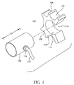
- the evaporation chamber is inside a metal cylinder 100 or evaporator head.
- the evaporator head is provided with a set of interchangeable adapters to fit pipes of different standard diameters.
- the adapter 102 in Figure 1 has different-sized, nearly semi-circular channels (104, 106, 108 and 110) for a conforming fit along relatively small (e.g., 15mm, 18mm, 22mm and 28 mm) diameter pipes. It would be sufficient, however, to provide a different adapter for each pipe diameter.
- the adapter 102 also has a greater than semicircular channel 112 having a radius sufficient to make a slide-on conforming fit over the outer surface of the evaporator head to receive the evaporator head and to hold the evaporator chamber in a position such that the length axis ("D" in Figure 1) is aligned parallel to the axis of a pipe placed in any of the semicircular channels.
- the coaxial hose (114) does not enter along the end of the cylinder, but rather enters through a hose coupling (116) that is located approximately midway along the length (D) of the cylinder.
- the hose coupling directs the inner tube of the hose generally perpendicular to the length axis of the evaporation chamber.
- the hose could be made to enter the chamber at a more acute angle, although there is no apparent advantage to do so.
- the channel 112 on the adapter has a arc of greater than 180 degrees, but preferably not more than about 330 degrees, so that the cylindrical evaporator head can slide into the channel with the hose and hose coupling in the slot 112 that is left open. It is most preferable to have the slot extend even further to permit the cylinder to rotate inside the coupling through about 45 degrees so that the hose can be positioned according to the space and obstacles around the pipe.
- the connection to the evaporator in a direction generally perpendicular to the pipe permits the freezer unit to be used in more confined space than orienting the hoses along the axis of the pipe, as in the prior pipe freezer.
- the adapter (120) of Figure 2 has two nearly semi-circular channels (124 and 122) conforming to the outer diameter of intermediate sized pipes (e. g. 35mm and 42mm, or 48mm and 60mm)).
- the adapter (128) of Figure 3 has a single nearly semi-circular channel (130) for a relatively large pipe (e.g. 73 mm or higher.).
- the greater than semi-circular channel (126 and 132) for the evaporator head is the same as the channel (112) on the adapter 102 of Figure 1.
- the hose coupling directs the hose in a direction essentially at right angle to the axis of the pipe.
- the inner tube (122) of the hose projects through the coupling to near the opposite inner wall of the cylinder to spray the liquid refrigerant against the wall.
- the refrigerant evaporates, the vapor is drawn back into the coupling to the outer tube of the hose. Since the coupling orients the inner tube essentially perpendicular to the length axis of the chamber, the distance from the end of the inner tube back into the coupling is not as great as when the inner tube is aligned with the length axis. This situation may result in less efficient heat transfer, as some liquid refrigerant may be drawn back into the outer hose and evaporate on return to the compressor rather than in the chamber.
- a metal baffle plate (124) is placed in the evaporator head, as shown in Figure 5.
- the baffle plate preferably is located in a chord of the cylindrical chamber near the hose coupling and extends toward and nearly to the end walls of the chamber.
- the baffle plate (124) may be a flat plate extending along the length of the chamber and terminate near the end plates, or as in Figures Sand 6, may then extend along the end plates of the chamber.
- the inner tube (122) of the refrigerant hose extends through the baffle plate.
- refrigerant sprayed from the inner tube (122) must migrate to the ends of the chamber to pass around the plate (124) and return to the midpoint of the chamber to be pulled into the coupling for return to the compressor/condenser (128) in the outer tube of the hose (126). This longer path makes more evaporation take place in the chamber and promotes more efficient heat exchange.
- FIGs 5 and 6 show a preferred configuration of baffle.
- the baffle (130) is saddle-shaped with a long flat top section (132) and two end sections (134) close to and essentially parallel to the end walls (136) of the cylinder. This creates a large evaporation space inside the baffle and forces the refrigerant to migrate essentially along the perimeter of the chamber before re-entering the hose coupling (116).
- Figure 7 shows another preferred construction of a cylindrical evaporation chamber.
- the chamber as described in previous embodiments, is formed as a hollow right cylinder (138) closed at both ends by end plates (136).
- the cylinder and plates are formed from a heat conductive metal, preferably aluminum.
- the surface of the cylinder should make a tight conforming fit into the adapter. This smooth fit would be lost if the cylinder became dented or scratched, as softer metals are prone to become in a working environment.
- a replaceable protective sleeve 140
- the sleeve is also made of a heat conductive metal, again preferably aluminum.
- the sleeve has a slot opening to allow the sleeve to slide past the hose coupling onto the cylinder.
- the adapters are sized to made a tight conformal fit with the sleeve. If the sleeve becomes dented or scratched, it can be replaced at much less cost than the evaporation chamber.
- Figure 8 shows an alternative shape of evaporation chamber.
- the chamber (150) is rectangular in cross section, with its length dimension directed into the paper.
- the adapter (152) has a rectangular channel for a conformal fit around three sides of the chamber.
- the rectangular chamber is slide into the adapter, and a bracket (154) is placed over it and held to the adapter by thumbscrews (156) in threaded bores of the adapter.
- the evaporator is similar to the cylindrical evaporator in that the hose coupling is located approximately midway along the evaporator's length dimension and is oriented perpendicular to the length axis of the chamber.
- a baffle is preferably located in the chamber between the outlet of the inner tube of the hose and the return to the outer tube to force refrigerant sprayed out of the inner tube to migrate from essentially the midway point of the chamber to an end wall and then back toward the midway point before entering the outer tube.
- evaporation chamber could also be used in accordance with the invention.
- the exterior of the chamber could include flat sides, such as a hexagonal or octagonal cylinder, and the adapters would be correspondingly configured to slide-on over the hexagonal or octagonal exterior.
Landscapes
- Engineering & Computer Science (AREA)
- General Engineering & Computer Science (AREA)
- Mechanical Engineering (AREA)
- Physics & Mathematics (AREA)
- Thermal Sciences (AREA)
- Chemical & Material Sciences (AREA)
- Combustion & Propulsion (AREA)
- Devices That Are Associated With Refrigeration Equipment (AREA)
- Removal Of Water From Condensation And Defrosting (AREA)
Priority Applications (1)
| Application Number | Priority Date | Filing Date | Title |
|---|---|---|---|
| EP07121552A EP1895249A3 (de) | 2001-08-02 | 2002-04-30 | Rohreinfriergerät mit Schnellverbindungs-Rohranschlussstücken |
Applications Claiming Priority (2)
| Application Number | Priority Date | Filing Date | Title |
|---|---|---|---|
| US921353 | 2001-08-02 | ||
| US09/921,353 US6408638B1 (en) | 2001-08-02 | 2001-08-02 | Pipe freezer with quick connect evaporator heads |
Related Child Applications (1)
| Application Number | Title | Priority Date | Filing Date |
|---|---|---|---|
| EP07121552A Division EP1895249A3 (de) | 2001-08-02 | 2002-04-30 | Rohreinfriergerät mit Schnellverbindungs-Rohranschlussstücken |
Publications (2)
| Publication Number | Publication Date |
|---|---|
| EP1281920A2 true EP1281920A2 (de) | 2003-02-05 |
| EP1281920A3 EP1281920A3 (de) | 2003-11-26 |
Family
ID=25445315
Family Applications (2)
| Application Number | Title | Priority Date | Filing Date |
|---|---|---|---|
| EP07121552A Withdrawn EP1895249A3 (de) | 2001-08-02 | 2002-04-30 | Rohreinfriergerät mit Schnellverbindungs-Rohranschlussstücken |
| EP02253044A Withdrawn EP1281920A3 (de) | 2001-08-02 | 2002-04-30 | Rohrgefriergerät mit Schnellanschlussrohrpassteilen |
Family Applications Before (1)
| Application Number | Title | Priority Date | Filing Date |
|---|---|---|---|
| EP07121552A Withdrawn EP1895249A3 (de) | 2001-08-02 | 2002-04-30 | Rohreinfriergerät mit Schnellverbindungs-Rohranschlussstücken |
Country Status (2)
| Country | Link |
|---|---|
| US (1) | US6408638B1 (de) |
| EP (2) | EP1895249A3 (de) |
Families Citing this family (3)
| Publication number | Priority date | Publication date | Assignee | Title |
|---|---|---|---|---|
| US6718789B1 (en) * | 2002-05-04 | 2004-04-13 | Arthur Radichio | Pipe freezer with defrost cycle |
| US8240167B2 (en) * | 2010-02-08 | 2012-08-14 | Ingram Michael T | Cryogenic freezing apparatus |
| US11761855B2 (en) * | 2019-07-03 | 2023-09-19 | Rtx Corporation | Apparatus and method for testing additively manufactured engine components |
Citations (1)
| Publication number | Priority date | Publication date | Assignee | Title |
|---|---|---|---|---|
| US5548965A (en) | 1995-05-31 | 1996-08-27 | Spectronics Corporation | Multi-cavity evaporator |
Family Cites Families (9)
| Publication number | Priority date | Publication date | Assignee | Title |
|---|---|---|---|---|
| US2572555A (en) * | 1944-11-03 | 1951-10-23 | Freez Seal Equipment Company L | Water pipe repairing equipment |
| US4267699A (en) * | 1979-02-21 | 1981-05-19 | Bahrenburg Harry H | Freeze isolation seal |
| US4309875A (en) * | 1979-05-14 | 1982-01-12 | Gerald M. D'Agostino | Pipe freezer or the like |
| DE3477417D1 (en) * | 1983-08-02 | 1989-04-27 | Ronald Hallett | Pipe freezing device |
| DE3903009A1 (de) * | 1989-02-02 | 1990-08-09 | Rothenberger Werkzeuge Masch | Vorrichtung zum einfrieren von mediendurchstroemten rohrleitungen, insbesondere von wasserleitungen |
| US5836167A (en) * | 1995-09-18 | 1998-11-17 | Nowsco Well Service Ltd. | Method and apparatus for freezing large pipe |
| US5680770A (en) * | 1996-11-04 | 1997-10-28 | Freeze Service, Inc. | Pipe freezing apparatus |
| US6141972A (en) * | 1998-12-07 | 2000-11-07 | Evans; Daniel J. | Invasive cryogenic tool and method for freezing the content of a pipe |
| EP1177404B1 (de) * | 1999-05-06 | 2008-10-29 | Arthur Radichio | Rohreinfriergerät |
-
2001
- 2001-08-02 US US09/921,353 patent/US6408638B1/en not_active Expired - Lifetime
-
2002
- 2002-04-30 EP EP07121552A patent/EP1895249A3/de not_active Withdrawn
- 2002-04-30 EP EP02253044A patent/EP1281920A3/de not_active Withdrawn
Patent Citations (3)
| Publication number | Priority date | Publication date | Assignee | Title |
|---|---|---|---|---|
| US5548965A (en) | 1995-05-31 | 1996-08-27 | Spectronics Corporation | Multi-cavity evaporator |
| GB2301661A (en) | 1995-05-31 | 1996-12-11 | Spectronics Corp | Evaporator for freezing the contents of a pipe |
| DE19617619A1 (de) | 1995-05-31 | 1996-12-12 | Spectronics Corp | Vorrichtung bzw. Verdampfer zum Vereisen eines Rohrabschnitts |
Also Published As
| Publication number | Publication date |
|---|---|
| EP1895249A3 (de) | 2008-08-06 |
| EP1281920A3 (de) | 2003-11-26 |
| EP1895249A2 (de) | 2008-03-05 |
| US6408638B1 (en) | 2002-06-25 |
Similar Documents
| Publication | Publication Date | Title |
|---|---|---|
| CN1133054C (zh) | 蒸发器 | |
| CN107166811B (zh) | 微通道热交换器的制冷剂分配器 | |
| US7331195B2 (en) | Refrigerant distribution device and method | |
| US8413715B2 (en) | Refrigerant evaporator with U-turn block and refrigerant-distributing holes | |
| US5875837A (en) | Liquid cooled two phase heat exchanger | |
| US9689594B2 (en) | Evaporator, and method of conditioning air | |
| US6598412B1 (en) | Interchangeable adapters for pipe freezer apparatus | |
| US10378826B2 (en) | Heat Exchanger | |
| AU784140B2 (en) | Heat exchanger header construction | |
| JPH0933165A (ja) | マルチキャビティ蒸発器 | |
| CN110857822A (zh) | 气液分离器及空调系统 | |
| EP0145114B1 (de) | Vorrichtung zum Einfrieren einer Rohrleitung | |
| EP1281920A2 (de) | Rohrgefriergerät mit Schnellanschlussrohrpassteilen | |
| EP1177404B1 (de) | Rohreinfriergerät | |
| US9574694B2 (en) | Pipe freezer system | |
| KR102224118B1 (ko) | 일체형 커넥터가 구비된 이중관 열교환기 | |
| CN110411075B (zh) | 冷凝器及空调 | |
| CN113063241B (zh) | 换热组件 | |
| US20250369662A1 (en) | Fluid distributor for a shell-and-tube flooded evaporator | |
| US20250003689A1 (en) | Energy storage system connection tube and condenser | |
| KR200168019Y1 (ko) | 냉장고용 응축기 | |
| KR20010096496A (ko) | 열교환 장치에 구비되는 냉각튜브 | |
| JPH01296067A (ja) | 二元冷凍機におけるデフロスト方法並びにその装置 |
Legal Events
| Date | Code | Title | Description |
|---|---|---|---|
| PUAI | Public reference made under article 153(3) epc to a published international application that has entered the european phase |
Free format text: ORIGINAL CODE: 0009012 |
|
| AK | Designated contracting states |
Designated state(s): AT BE CH CY DE DK ES FI FR GB GR IE IT LI LU MC NL PT SE TR |
|
| AX | Request for extension of the european patent |
Extension state: AL LT LV MK RO SI |
|
| PUAL | Search report despatched |
Free format text: ORIGINAL CODE: 0009013 |
|
| AK | Designated contracting states |
Kind code of ref document: A3 Designated state(s): AT BE CH CY DE DK ES FI FR GB GR IE IT LI LU MC NL PT SE TR |
|
| AX | Request for extension of the european patent |
Extension state: AL LT LV MK RO SI |
|
| 17P | Request for examination filed |
Effective date: 20040211 |
|
| AKX | Designation fees paid |
Designated state(s): AT BE CH CY DE DK ES FI FR GB GR IE IT LI LU MC NL PT SE TR |
|
| STAA | Information on the status of an ep patent application or granted ep patent |
Free format text: STATUS: THE APPLICATION IS DEEMED TO BE WITHDRAWN |
|
| 18D | Application deemed to be withdrawn |
Effective date: 20081029 |