EP1281650A1 - Method and device for grouping and further transporting flat articles - Google Patents
Method and device for grouping and further transporting flat articles Download PDFInfo
- Publication number
- EP1281650A1 EP1281650A1 EP02013235A EP02013235A EP1281650A1 EP 1281650 A1 EP1281650 A1 EP 1281650A1 EP 02013235 A EP02013235 A EP 02013235A EP 02013235 A EP02013235 A EP 02013235A EP 1281650 A1 EP1281650 A1 EP 1281650A1
- Authority
- EP
- European Patent Office
- Prior art keywords
- transport
- objects
- gripper
- conveyor
- curve
- Prior art date
- Legal status (The legal status is an assumption and is not a legal conclusion. Google has not performed a legal analysis and makes no representation as to the accuracy of the status listed.)
- Granted
Links
Images


Classifications
-
- B—PERFORMING OPERATIONS; TRANSPORTING
- B65—CONVEYING; PACKING; STORING; HANDLING THIN OR FILAMENTARY MATERIAL
- B65H—HANDLING THIN OR FILAMENTARY MATERIAL, e.g. SHEETS, WEBS, CABLES
- B65H29/00—Delivering or advancing articles from machines; Advancing articles to or into piles
- B65H29/02—Delivering or advancing articles from machines; Advancing articles to or into piles by mechanical grippers engaging the leading edge only of the articles
- B65H29/04—Delivering or advancing articles from machines; Advancing articles to or into piles by mechanical grippers engaging the leading edge only of the articles the grippers being carried by endless chains or bands
- B65H29/042—Intermediate conveyors, e.g. transferring devices
-
- B—PERFORMING OPERATIONS; TRANSPORTING
- B65—CONVEYING; PACKING; STORING; HANDLING THIN OR FILAMENTARY MATERIAL
- B65H—HANDLING THIN OR FILAMENTARY MATERIAL, e.g. SHEETS, WEBS, CABLES
- B65H29/00—Delivering or advancing articles from machines; Advancing articles to or into piles
- B65H29/003—Delivering or advancing articles from machines; Advancing articles to or into piles by grippers
-
- B—PERFORMING OPERATIONS; TRANSPORTING
- B65—CONVEYING; PACKING; STORING; HANDLING THIN OR FILAMENTARY MATERIAL
- B65H—HANDLING THIN OR FILAMENTARY MATERIAL, e.g. SHEETS, WEBS, CABLES
- B65H2301/00—Handling processes for sheets or webs
- B65H2301/30—Orientation, displacement, position of the handled material
- B65H2301/32—Orientation of handled material
- B65H2301/323—Hanging
-
- B—PERFORMING OPERATIONS; TRANSPORTING
- B65—CONVEYING; PACKING; STORING; HANDLING THIN OR FILAMENTARY MATERIAL
- B65H—HANDLING THIN OR FILAMENTARY MATERIAL, e.g. SHEETS, WEBS, CABLES
- B65H2301/00—Handling processes for sheets or webs
- B65H2301/40—Type of handling process
- B65H2301/42—Piling, depiling, handling piles
- B65H2301/422—Handling piles, sets or stacks of articles
- B65H2301/4224—Gripping piles, sets or stacks of articles
- B65H2301/42242—Gripping piles, sets or stacks of articles by acting on the outermost articles of the pile for clamping the pile
-
- B—PERFORMING OPERATIONS; TRANSPORTING
- B65—CONVEYING; PACKING; STORING; HANDLING THIN OR FILAMENTARY MATERIAL
- B65H—HANDLING THIN OR FILAMENTARY MATERIAL, e.g. SHEETS, WEBS, CABLES
- B65H2301/00—Handling processes for sheets or webs
- B65H2301/40—Type of handling process
- B65H2301/43—Gathering; Associating; Assembling
- B65H2301/435—Gathering; Associating; Assembling on collecting conveyor
- B65H2301/4354—Gathering; Associating; Assembling on collecting conveyor with grippers
-
- B—PERFORMING OPERATIONS; TRANSPORTING
- B65—CONVEYING; PACKING; STORING; HANDLING THIN OR FILAMENTARY MATERIAL
- B65H—HANDLING THIN OR FILAMENTARY MATERIAL, e.g. SHEETS, WEBS, CABLES
- B65H2301/00—Handling processes for sheets or webs
- B65H2301/40—Type of handling process
- B65H2301/44—Moving, forwarding, guiding material
- B65H2301/447—Moving, forwarding, guiding material transferring material between transport devices
- B65H2301/4471—Grippers, e.g. moved in paths enclosing an area
- B65H2301/44712—Grippers, e.g. moved in paths enclosing an area carried by chains or bands
-
- B—PERFORMING OPERATIONS; TRANSPORTING
- B65—CONVEYING; PACKING; STORING; HANDLING THIN OR FILAMENTARY MATERIAL
- B65H—HANDLING THIN OR FILAMENTARY MATERIAL, e.g. SHEETS, WEBS, CABLES
- B65H2301/00—Handling processes for sheets or webs
- B65H2301/40—Type of handling process
- B65H2301/44—Moving, forwarding, guiding material
- B65H2301/447—Moving, forwarding, guiding material transferring material between transport devices
- B65H2301/4471—Grippers, e.g. moved in paths enclosing an area
- B65H2301/44714—Grippers, e.g. moved in paths enclosing an area carried by rotating members
Landscapes
- Engineering & Computer Science (AREA)
- Mechanical Engineering (AREA)
- Specific Conveyance Elements (AREA)
- Feeding Of Articles By Means Other Than Belts Or Rollers (AREA)
- Discharge By Other Means (AREA)
- Attitude Control For Articles On Conveyors (AREA)
- Making Paper Articles (AREA)
- Intermediate Stations On Conveyors (AREA)
Abstract
Description
Die vorliegende Erfindung betrifft ein Verfahren und eine Vorrichtung zum Zusammenbringen und gemeinsamen Weitertransportieren von jeweils mindestens zwei flexiblen, flächigen Gegenständen.The present invention relates to a method and a Device for bringing together and further transport together of at least two flexible, flat objects.
In Druckereien, insbesondere deren Versandräumen und in Druckereierzeugnisse be- und verarbeitenden Betrieben fallen die Druckereierzeugnisse oft einzelweise von Transportklammern eines Förderers gehalten an. Diese Art des Transports ist insbesondere bei grossen Verarbeitungskapazitäten mit hohen Fördergeschwindigkeiten verbunden, was für die Druckereierzeugnisse selber jedoch auch die Laufruhe und Lebensdauer der Fördereinrichtung nachteilig sein kann.In print shops, especially their mailrooms and in Printing and processing companies the printed matter often falls off one by one Conveyor clamps held on. This kind of transportation is particularly large Processing capacities with high conveyor speeds connected, but what for the printed products themselves also the smooth running and service life of the conveyor can be disadvantageous.
Es ist deshalb eine Aufgabe der vorliegenden Erfindung, ein Verfahren vorzuschlagen und eine Vorrichtung zu schaffen, bei dem bzw. mit der einzelweise transportierte flexible flächige Gegenstände auf einfache Art und Weise für den gemeinsamen Weitertransport von jeweils zwei oder mehr Gegenständen zusammengebracht werden können.It is therefore an object of the present invention propose a method and a device create, with which or transported individually flexible flat objects in a simple way for the joint further transport of two or more items can be brought together.
Diese Aufgabe wird mit einem Verfahren gemäss Anspruch 1 und einer Vorrichtung gemäss Anspruch 4 gelöst.This task is accomplished with a method according to claim 1 and a device according to claim 4 solved.
Das erfindungsgemässe Verfahren und die erfindungsgemässe Vorrichtung erlauben das Zusammenbringen von jeweils mindestens zwei flexiblen flächigen Gegenständen während des Transports, ohne dass die Gegenstände angehalten oder gestapelt werden müssen. Dies erlaubt bei schonender Behandlung der Gegenstände grosse Verarbeitungskapazitäten bei ruhigem Lauf der entsprechenden Vorrichtung.The inventive method and the inventive Device allow the bringing together of each at least two flexible flat objects during of transport without the objects being stopped or need to be stacked. This allows for more gentle Treatment of objects with large processing capacities with the corresponding device running smoothly.
Bevorzugte Weiterbildungsformen des erfindungsgemässen Verfahrens und bevorzugte Ausbildungsformen der erfindungsgemässen Vorrichtung sind in den abhängigen Patentansprüchen angegeben.Preferred forms of further development of the invention Procedures and preferred forms of training Device according to the invention are in the dependent Claims specified.
Die Erfindung wird anhand von in der Zeichnung dargestellten Ausführungsformen näher erläutert. Es zeigen rein schematisch:
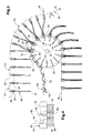
- Fig. 1
- in Ansicht einen Förderer, mittels welchem die anfallenden Gegenstände transportiert werden, einem Greiferrad, mittels welchem jeweils zwei der Gegenstände zusammengebracht und einem Wegförderer übergeben werden;
- Fig. 2
- in einem Axialschnitt einen Teil des Greiferrades von Fig. 1;
- Fig. 3
- in gleicher Darstellung wie Fig. 1 den Förderer, mittels welchem die anfallenden Gegenstände transportiert werden, und einen Greiferförderer, mittels dem jeweils zwei der Gegenstände zusammengebracht und weggefördert werden;
- Fig. 4
- in gleicher Darstellung wie Fig. 2 einen Teil des Greiferförderers und eines Umlenkrades mit Stützelementen für die Gegenstände;
- Fig. 5
- in gleicher Darstellung wie Fig. 1 und 3 einen Teil der dort gezeigten Vorrichtung, bei welcher die Stützelemente auf die das jeweils vorauslaufende der beiden zusammenzubringenden Gegenstände haltende Transportklammer ausgerichtet sind;
- Fig. 6
- in gleicher Darstellung wie Fig. 5 einen Teil der Vorrichtung gemäss Fig. 1 und 3, bei welcher die Stützelemente auf die das jeweils nachlaufende der beiden zusammenzubringenden Gegenstände haltende Transportklammer ausgerichtet sind;
- Fig. 7
- in gleicher Darstellung wie Fig. 1 und 3 eine weitere Ausbildungsform der erfindungsgemässen Vorrichtung, bei welcher der Förderer mittels welchem die anfallenden Gegenstände transportiert werden, auch zum Wegtransport der zusammengebrachten Gegenstände dient; und
- Fig. 8
- in gleicher Darstellung wie Fig. 2 und 4, einen Teil des radartig ausgebildeten Greiferförderers gemäss Fig. 7.
- Fig. 1
- in view a conveyor, by means of which the resulting objects are transported, a gripper wheel, by means of which two of the objects are brought together and handed over to a conveyor;
- Fig. 2
- in an axial section part of the gripper wheel of Fig. 1;
- Fig. 3
- in the same representation as Figure 1, the conveyor, by means of which the resulting objects are transported, and a gripper conveyor, by means of which two of the objects are brought together and transported away;
- Fig. 4
- in the same representation as Figure 2 part of the gripper conveyor and a deflection wheel with support elements for the objects.
- Fig. 5
- in the same representation as FIGS. 1 and 3, part of the device shown there, in which the support elements are aligned with the transport clamp holding the respectively leading one of the two objects to be brought together;
- Fig. 6
- in the same representation as FIG. 5, part of the device according to FIGS. 1 and 3, in which the support elements are aligned with the transport clamp holding the trailing of the two objects to be brought together;
- Fig. 7
- in the same representation as FIGS. 1 and 3, a further embodiment of the device according to the invention, in which the conveyor, by means of which the resulting objects are transported, also serves to transport away the objects brought together; and
- Fig. 8
- in the same representation as FIGS. 2 and 4, a part of the wheel-like gripper conveyor according to FIG. 7.
Die in den Fig. 1 und 2 gezeigte Vorrichtung weist einen
Förderer 10 mit einem horizontalen Förderabschnitt 12, einem
in Förderrichtung F1 gesehen daran anschliessenden Kurvenabschnitt
14 und einen diesem folgenden weiteren Kurvenabschnitt
16 auf. Der Förderabschnitt 12 und die beiden
Kurvenabschnitte 14 und 16 befinden sich in einer Vertikalebene.
Der Kurvenabschnitt 14 folgt um nahezu 90° einem
Kreisbogen um eine Achse 18, die sich unterhalb des Förderabschnitts
12 befindet. Der weitere Kurvenabschnitt 16
weist bezüglich des Kurvenabschnitts 14 eine entgegengesetzte
Krümmung auf.The device shown in FIGS. 1 and 2 has a
Beim Förderer 10 handelt es sich um einen allgemein bekannten
Klammertransporteur mit im Abstand A hintereinander
an einem in Förderrichtung F1 kontinuierlich umlaufend
angetriebenen Förderorgan 20, beispielsweise ein Zugorgan
angeordneten Transportklammern 22. Der Weg den die Transportklammern
22 durchlaufen definiert eine Förderbahn 24
entlang der die von den Transportklammern 22 einzelweise
gehaltenen flexiblen flächigen Gegenstände 26 zu transportieren
sind. Bei den Gegenständen 26 handelt es sich im
vorliegenden Fall um Druckereiprodukte, wie Zeitungen,
Zeitschriften und dergleichen. Die Transportklammern 22
sind dazu bestimmt, die rechteckigen Gegenstände bei einer
obenliegenden ersten Kante 28, die im Bereich des ersten
Kurvenabschnitts 14 in radialer Richtung gesehen aussenliegend
ist und parallel zur Achse 18 verläuft, gehalten
in den Kurvenabschnitt 14 zu transportieren und am Ende
dieses Kurvenabschnitts 14 frei zu geben. Zu diesem Zweck
ist dort ein mit einem Pfeil angedeutetes Öffnungsorgan 30
angeordnet, welches die an ihm vorbeilaufenden Transportklammern
22 von einer Schliessstellung in eine Offenstellung
umsteuert. Wie dies der Fig. 1 unschwer entnehmbar
ist, sind die mehrblättrigen gefalteten Gegenstände 26 bei
der dem Falz gegenüberliegenden offenen ersten Kante 28
gehalten; der Falz bildet eine zweite Kante 32.The
Auf einer zur Achse 18 koaxialen Welle 34 sitzt ein Greiferrad
36, das in Drehrichtung D mit gleicher Winkelgeschwindigkeit
angetrieben ist, wie die Transportklammern
22 im Kurvenabschnitt 14. Wie dies insbesondere aus der
Fig. 2 hervorgeht, weist das Greiferrad 36 zwei kreisrunde
Tragscheiben 38 auf, zwischen welchen in Umfangsrichtung
verteilt Greifer 40 angeordnet sind. Das Greiferrad 36
bildet somit einen Greiferförderer 42 mit entlang einer
kreisförmigen Umlaufbahn 44 um die Achse 18 bewegten Greifern
40.A gripper wheel is seated on a
Jeder Greifer 40 weist zwei ein Greifermaul 46 bildende
Greiferbacken 48 auf, die aus einer gespreizten Offenstellung
50 symmetrisch zu einer Radialen, in eine Schliessstellung
50' und wieder zurück verschwenkbar sind. Greifer
40 dieser Art sind allgemein bekannt und werden vorzugsweise
über ortsfeste Kulissen angesteuert. Die Greifer 40
sind um die Achse 18 zueinander in einem Winkel α angeordnet,
der doppelt so gross ist, wie der Winkel zwischen
zwei Transportklammern 22 im Kurvenabschnitt 14. Der Abstand
zwischen dem Förderer 10 und dem Greiferrad 36 ist
derart gewählt, dass beim Übergang vom Förderabschnitt 12
in den Kurvenabschnitt 14 die zweiten Kanten 32 der Gegenstände
26 die Tragscheiben 38 umfangsseitig gerade berühren
oder nahe an diese herankommen.Each
Jedem Greifer 40 ist ein Abstützorgan 52 zugeordnet, das
im vorliegenden Fall durch zwei Abstützbleche 54 gebildet
ist, die je an einer der Tragscheiben 38 in radialer Richtung
verschiebbar angeordnet sind. In bevorzugter Weise
erfolgt die Verschiebung in bekannter Art und Weise kulissengesteuert
- die der Förderrichtung F1 gleichgerichtet
ist. In Drehrichtung D gesehen, befindet sich das Abstützorgan
52 bei der Schwenkachse der jeweils vorauslaufenden
Greiferbacke 48 des zugeordneten Greifers 40.A
Unterhalb des Greiferrades 36 und in derselben Vertikalebene
wie der Förderer 10 und die Greifer 40 verläuft in
horizontaler Richtung ein Wegförderer 56. Seine ebenfalls
an einem Zugorgan 20' im Abstand B hintereinander angeordneten
Transportgreifer 58 sind gleicher oder ähnlicher
Bauart wie die Greifer 40 des Greiferrades 36, wobei die
Greifermäuler 46' in Richtung gegen oben gerichtet sind.
Der Abstand zwischen den Tragscheiben 38 und dem Grund der
Greifermäuler 46' entspricht, gemessen in vertikaler Richtung
unterhalb der Achse 18, wenigstens annähernd dem Abstand
zwischen der ersten Kante 28 und dem Falz 32 der Gegenstände
26. Der Abstand B der Transportgreifer 58 und
ihre Fördergeschwindigkeit F2 sind derart aufeinander abgestimmt,
dass vertikal unterhalb der Achse 18 mit jedem
Greifer 40 jeweils ein Transportgreifer 58 zusammentrifft.
In vertikaler Richtung, unterhalb der Achse 18, ist dem
Wegförderer 56 ein Schliessorgan 60 zugeordnet, das dazu
bestimmt ist, die in Offenstellung 50 in Förderrichtung F2
ankommenden Transportgreifer 58 in Schliessstellung zu
überführen.Below the
Die Funktionsweise der in den Fig. 1 und 2 gezeigten Vorrichtung
ist wie folgt. Jeder zweite in Hängelage durch
den Förderabschnitt 12 dem Kurvenabschnitt 14 zugeführte
Gegenstand 26 läuft kurz vor dem Erreichen des Kurvenabschnitts
14 auf ein in radialer Richtung ausgefahrenes Abstützorgan
52 auf, durch welches es in einem an die zweite
Kante angrenzenden Bereich auf der, in Förderrichtung F1
gesehen, vorauslaufenden Seite 62 abgestützt wird. Wie
dies anhand der strichpunktiert gezeigten radialen Geraden
erkennbar ist, sind die Abstützorgane 52 jeweils auf die
Mitte zwischen zwei Transportklammern 22 ausgerichtet, was
zur Folge hat, dass der am Abstützorgan 52 zur Anlage gelangende
Gegenstand 26 leicht S-förmig gebogen wird. Der
diesem Gegenstand 26 folgende Gegenstand 26 legt sich beim
oder kurz nach dem Durchlaufen der Vertikalebene durch die
Achse 18 mit seinem radial innenliegenden, an die zweite
Kante 32 angrenzenden Bereich an jenen Gegenstand 26 an,
der vom Abstützorgan 52 abgestützt ist. Infolge der
Schwerkraft wird dadurch im Kurvenabschnitt 14 der jeweils
nachlaufende Gegenstand 26 bezüglich des vorauslaufenden
Gegenstandes 26 entgegengesetzt leicht S-förmig verbogen,
so dass die beiden Gegenstände 26 ein V bilden. Durch das
Schliessen des dem betreffenden Stützorgan 52 zugeordneten
Greifers 40 werden die beiden Gegenstände 26 bei der zweiten
Kante 32 gemeinsam erfasst und festgehalten. Die
Transportklammern 22 geben beim Vorbeilaufen am Öffnungsorgan
30 den betreffenden Gegenstand 26 frei. Die beiden
danach jeweils nur noch von einem Greifer 40 gehaltenen
Gegenstände 26 biegen sich infolge ihrer Flexibilität derart,
dass ihr freier Endbereich in Richtung gegen unten
hängt. Im Bereich unterhalb des Greifrades 36 trifft mit
jedem Paar von einem Greifer 40 gehaltenen Gegenstände 26
ein Transportgreifer 58 zusammen, welcher diese Gegenstände
26 von unten bei deren erster Kante 28 umgreift und,
durch das Schliesssorgan 60 ausgelöst, für den Weitertransport
erfasst, wonach der zugeordnete Greifer 40 geöffnet
wird, um die jeweiligen Gegenstände 26 frei zu geben.The operation of the device shown in FIGS. 1 and 2 is as follows. Every
In bevorzugter Weise sind die Transportgreifer 58 am Zugorgan
20' schwenkbar angeordnet, um die Gegenstände 26 in
Förderrichtung F2 gesehen in Richtung gegen vorne zu
schwenken, wie dies Fig. 1 zeigt. Es ist jedoch auch denkbar,
eine Schwenkbewegung in Richtung rückwärts auszuführen.In a preferred manner, the
Der Vollständigkeit halber sei erwähnt, dass die Abstützorgane
52 nach dem Überführen der Greifer 40 in die
Schliessstellung 50' in radialer Richtung gegen innen verschoben
werden, so dass die paarweise von einem Greifer 40
gehaltenen Gegenstände 26 vom Abstützorgan 52 nicht mehr
abgestützt sind. Der Bereich, in welchem sich die Gegenstände
26 in Richtung gegen unten biegen können, wird dadurch
vergrössert. Nach dem vollständigen Öffnen der Greifer
40 werden die Abstützorgane 52 in radialer Richtung
wieder ausgefahren, so dass sie spätestens beim Erreichen
des Zenits ihrer Umlaufbahn 44 ihre radial äusserste Stellung
wieder erreicht haben.For the sake of completeness it should be mentioned that the
Mit der in der Fig. 1 gezeigten Vorrichtung werden hintereinander
einzelweise anfallende Gegenstände 26 während des
kontinuierlichen Transports paarweise zusammengefasst und
für den Weitertransport dem Wegförderer 56 übergeben, welcher
beispielsweise bei dem Abstand A zwischen den Transportklammern
22 entsprechenden Abstand B zwischen den
Transportgreifern 58 nur noch mit halber Geschwindigkeit
wie der Förderer 10 angetrieben sein muss. Der Abstand B
muss jedoch nicht jenem von A entsprechen; entsprechend
dem Abstandsverhältnis wäre einzig der Durchmesser des
Greiferrades 36 anzupassen. Es ist auch denkbar, mit einem
Greifer 40 jeweils mehr als zwei, beispielsweise drei Gegenstände
26 zu erfassen, wozu der Abstand zwischen den
Greifern 40 entsprechend anzupassen wäre.With the device shown in FIG. 1, one behind the other
Bei der in den Fig. 3 und 4 gezeigten Ausbildungsform der
erfindungsgemässen Vorrichtung ist der Förderer 10 gleich
ausgebildet wie bei jener gemäss Fig. 1. Er wird deshalb
nicht mehr beschrieben. Die Bezugszeichen entsprechen jenen
der Fig. 1 und 2.In the embodiment shown in Figs. 3 and 4
The
Gegenüber der Ausbildungsform gemäss den Fig. 1 und 2 ist
bei der Ausbildungsform gemäss den Fig. 3 und 4 der Greiferförderer
42 unterschiedlich ausgebildet. Er weist wiederum
zwei parallele Tragscheiben 38 auf, an welchen die
jeweils das Stützorgan 52 bildende Abstützbleche 54 in radialer
Richtung verschiebbar angeordnet sind. Die Greifer
40 sind nun jedoch nicht mehr an den Tragscheiben 38, sondern
an einem in sich geschlossenen weiteren Zugorgan 64
angeordnet. Dieses ist zwischen den Tragscheiben 38 um die
Achse 18 derart herumgeführt, dass jedem Abstützorgan 52
ein Greifer 40 zusammentrifft und zwar, bevor die Abstützorgane
52 jeweils den Zenit ihrer kreisförmigen Umlaufbahn
um die Achse 18 erreicht haben. In bevorzugter Weise
sind die Tragscheiben 38 mit Ausnehmungen oder Vorsprüngen
für die Greifer 40 versehen. Die Greifer 40 begleiten dann
das zugeordnete Abstützorgan 52 - im dem Kurvenabschnitt
14 des Förderers 10 zugeordneten Bereich - bis vertikal
unterhalb der Achse 18, wo die Greifer 40 in horizontaler
Richtung die Tragscheiben 38 verlassen. Im Bereich der
Tragscheiben 38 bilden die Greifer 40 zusammen mit den
Tragscheiben 38 einen Abschnitt des Greiferrades 36 mit
derselben Funktion wie weiter oben im Zusammenhang mit den
Fig. 1 und 2 beschrieben. Die paarweise von einem Greifer
40 erfassten und gehaltenen Gegenstände werden mittels des
Greiferförderers 42 in Hängelage wegtransportiert. Mit anderen
Worten ist der Wegförderer 56 der Ausbildungsform
gemäss den Fig. 1 und 2 durch den Greiferförderer 42 ersetzt.Compared to the form of training according to FIGS. 1 and 2
3 and 4 of the gripper conveyor in the
Fig. 5 zeigt einen Ausschnitt des ersten Kurvenabschnitts
14 und zwei Greifer 40 des Greiferförderers 42 der erfindungsgemässen
Vorrichtung gemäss den Fig. 1 und 2 beziehungsweise
3 und 4. Der einzige Unterschied besteht nun
darin, dass die Abstützorgane 52 und somit die ihnen zugeordneten
Greifer 40 in Drehrichtung D gesehen, auf die jeweils
vorauslaufende Transportklammer 22 der beiden Transportklammern
22 ausgerichtet sind, welche jene Gegenstände
26 transportieren, die von einem Greifer 40 zu erfassen
sind. Dies hat nun zur Folge, dass er von der jeweils vorauslaufenden
Transportklammer 42 gehaltene Gegenstand 26,
infolge Anliegens am Abstützorgan 52, nicht mehr S-förmig
entgegen der Förderrichtung verbogen wird, sondern wenigstens
annähernd in einer Radialebene verbleibt. Der von
der jeweils nachlaufenden Transportklammer 22 gehaltene
Gegenstand 26 verbiegt sich nun jedoch stärker S-förmig,
was dazu führt, dass die diesen beiden Gegenständen 26 zugeordneten
zweiten Kante 32 - die Falzkanten - in radialer
Richtung versetzt angeordnet sind und zwar befindet sich
die zweite Kante 32 des nachlaufenden Gegenstandes 26 in
radialer Richtung gesehen weiter aussen als jene des vorauslaufenden
Gegenstandes 26. Die beiden Gegenstände 26
werden jeweils in dieser Lage vom Greifer 40 erfasst und
für den Weitertransport festgehalten, was zur Folge hat,
dass nach dem Freigeben durch die Transportklammer 22 der
nachlaufende Gegenstand 26 mit einem an die erste Kante 28
anschliessenden streifenförmigen Endbereich über die erste
Kante 28 des vorauslaufenden Gegenstandes 26 vorsteht. Dadurch
können die beiden Gegenstände 26 für die Weiterverarbeitung
problemlos wieder voneinander getrennt werden.5 shows a section of the
Im Gegensatz zur Ausbildung gemäss Fig. 5 sind bei jener
gemäss Fig. 6 die Greifer 40 und zugeordneten Abstützorgane
52 auf die Transportklammern 22 derart ausgerichtet,
dass die in Drehrichtung D gesehen nachlaufende Greiferbacke
48 der Greifer 40 zusammen mit jener Transportklammer
22 des Förderers 10 auf einer Radialen liegt, die den
nachlaufenden der beiden Gegenstände 26 herantransportiert,
welche vom Greifer 40 zu erfassen sind. Dies hat
nun zur Folge, dass sich der am Abstützorgan 52 anliegende
vorauslaufende Gegenstand 26 S-förmig verbiegt, während
der nachlaufende Gegenstand 26 im wesentlichen seine ebene
Form beibehält. Die zweite Kante 32 des jeweils vorauslaufenden
Gegenstandes 26 ist gegenüber jener des nachlaufenden
Gegenstandes 26 in radialer Richtung gegen aussen verschoben.
Da nun nach der Freigabe durch die Transportklammer
22 der jeweils vorauslaufende Gegenstand 26 mit einem
an die erste Kante 28 angrenzenden streifenförmigen Bereich
über die erste Kante 28 des nachlaufenden Gegenstandes
26 vorsteht, ist ein späteres problemloses Trennen
dieser Gegenstände 26 gewährleistet.In contrast to the design according to FIG
6, the
Durch das Verändern der Phasenverschiebung zwischen dem
Förderer 10 und dem Greiferförderer 42 lässt sich die gewünschte
Ausrichtung des Abstützorgans 52 und Greiferbakkens
48 einstellen. By changing the phase shift between the
Bei der in den Fig. 7 und 8 gezeigten Ausbildungsform ist
der Greiferförderer 42 als Greiferrad 36 ausgebildet, wie
in den Fig. 1 und 2 gezeigt und weiter oben beschrieben.
Der Kurvenabschnitt 14 des Förderers 10 erstreckt sich nun
jedoch um mehr als 180° - im vorliegenden Fall ungefähr
210° - koaxial um die Achse 18 herum. An den Kurvenabschnitt
14 schliesst ein entgegengesetzt gekrümmter weiterer
Kurvenabschnitt 16 an, dessen stromabwärts liegendes
Ende in horizontaler Richtung verläuft. Der Unterschied zu
den weiter oben gezeigten und beschriebenen Ausbildungsformen
besteht darin, dass der Förderer 10 bei der in den
Fig. 7 und 8 gezeigten Ausbildungsform auch für den Wegtransport
der paarweise zusammengebrachten Gegenstände 26
dient, wobei dann jedoch für den Wegtransport nur jede
zweite Transportklammer 22 aktiv ist, was zur Folge hat,
dass aufeinanderfolgende Transportklammern 22 unterschiedlich
gesteuert werden müssen.In the embodiment shown in FIGS. 7 and 8
the
Die beiden Backen 68 wenigstens jeder zweiten Transportklammer
22 sind individuell gesteuert. Es können jedoch
auch die Backen 68 aller Transportklammern 22 individuell
gesteuert sein. Transportklammern dieser Bauart sind allgemein
bekannt.The two
Die unterschiedliche Steuerung aufeinanderfolgender Transportklammern
22 kann beispielsweise dadurch geschehen,
dass die Steuerorgane für die Backen 68 jeder zweiten
Transportklammer 22 auf der einen Seite des Kurvenabschnitts
14 und jene für die Backen 68 der anderen Transportklammern
22 auf der anderen Seite angeordnet sind. Erreicht
eine Transportklammer 22, welche den vorauslaufenden
der beiden vom zugeordneten Greifer 40 gehaltenen Gegenstände
26 festhält etwa in der Darstellung gemäss Fig.
7 gesehen - die Stellung 5 Uhr, verschwenkt das Öffnungsorgan
30 die in Förderrichtung F1 gesehen nachlaufende Bakke
68 der Transportklammer 22, in Offenstellung, während
die vorauslaufende Backe 68 die etwa in radialer Richtung
verlaufende Schliessstellung beibehält. Jedoch werden die
beiden Backen 68 des nachlaufenden Greifers 40 gleichzeitig
in Offenstellung verbracht. Der vorauslaufende der
beiden Gegenstände 26 ist somit bei seiner ersten Kante 28
von einer Backe 68 abgestützt, während der nachlaufende
Gegenstand 26 freigegeben ist und sich flächig an den abgestützten
Gegenstand 26 anlegt. Anschliessend verschwenkt
das Schliessorgan 60 die nachlaufende Backe 68 der dem
vorlaufenden der beiden Gegenstände 26 zugeordneten Transportklammer
22 in Schliessstellung, wodurch nun die beiden
flächig aneinander anliegenden Gegenstände 26 bei ihrer
ersten Kante 28 von der Transportklammer 22 für den Wegtransport
festgehalten sind. Die nachlaufende Transportklammer
22 wird nicht in Schliessstellung überführt.The different control of
Mit dem Pfeil 66 ist ein Stossorgan angedeutet, welches
dazu bestimmt ist, den nachlaufenden der beiden von einem
Greifer 40 gehaltenen Gegenstände 26 in Förderrichtung F1
in flächige Anlage an den vorauslaufenden Gegenstand 26 zu
stossen.The
Es ist auch möglich, die Abstützorgane 52 nicht an Tragscheiben
38 sondern an den Greifern 40 selber anzuordnen.It is also possible that the
Es ist auch denkbar, die Transportklammern 22 und/oder
Greifer 40 und/oder Transportgreifer 58 an schienengeführten
individuellen Wagen oder Schlitten anzuordnen.It is also conceivable for the transport clips 22 and / or
Claims (10)
Applications Claiming Priority (2)
| Application Number | Priority Date | Filing Date | Title |
|---|---|---|---|
| CH14172001 | 2001-07-30 | ||
| CH14172001 | 2001-07-30 |
Publications (2)
| Publication Number | Publication Date |
|---|---|
| EP1281650A1 true EP1281650A1 (en) | 2003-02-05 |
| EP1281650B1 EP1281650B1 (en) | 2005-08-17 |
Family
ID=4565461
Family Applications (1)
| Application Number | Title | Priority Date | Filing Date |
|---|---|---|---|
| EP02013235A Expired - Lifetime EP1281650B1 (en) | 2001-07-30 | 2002-06-17 | Method and device for grouping and further transporting flat articles |
Country Status (5)
| Country | Link |
|---|---|
| US (1) | US6672447B2 (en) |
| EP (1) | EP1281650B1 (en) |
| AT (1) | ATE302154T1 (en) |
| DE (1) | DE50203934D1 (en) |
| DK (1) | DK1281650T3 (en) |
Cited By (6)
| Publication number | Priority date | Publication date | Assignee | Title |
|---|---|---|---|---|
| CH700151A1 (en) * | 2008-12-24 | 2010-06-30 | Ferag Ag | Device and method for the transfer of flexible flat objects. |
| CH700240A1 (en) * | 2009-01-08 | 2010-07-15 | Ferag Ag | Device and method for transfer of flexible flat objects. |
| EP2216280A1 (en) * | 2009-02-06 | 2010-08-11 | Ferag AG | Device and process for transferring flexible flat objects |
| WO2011120175A1 (en) * | 2010-04-01 | 2011-10-06 | Ferag Ag | Device and method for transferring flexible, flat articles |
| WO2012034242A1 (en) * | 2010-09-17 | 2012-03-22 | Ferag Ag | Device for transferring products to a gripper conveyor |
| EP2706031A1 (en) | 2012-09-05 | 2014-03-12 | Ferag AG | Device for transferring of product units from a feeder conveyor to a removal conveyor |
Families Citing this family (8)
| Publication number | Priority date | Publication date | Assignee | Title |
|---|---|---|---|---|
| DK1426293T3 (en) * | 2002-11-29 | 2006-10-09 | Ferag Ag | Method and device for packaging flat articles |
| US6851544B2 (en) * | 2003-05-19 | 2005-02-08 | Graphic Management Associates, Inc. | Transfer device |
| ATE394332T1 (en) * | 2003-12-22 | 2008-05-15 | Ferag Ag | METHOD AND DEVICE FOR STABILIZING AND POSITIONING FLAT OBJECTS |
| EP1588971B2 (en) * | 2004-04-22 | 2019-06-19 | Ferag AG | Method and apparatus for handling of printed products |
| EP1717179B1 (en) * | 2005-04-29 | 2008-08-20 | Müller Martini Holding AG | Device for stablilizing printed products transported in a stream along a transport path, hanging in grippers of a transport device |
| CH712816B1 (en) * | 2006-12-22 | 2018-02-15 | Ferag Ag | Method and device for conveying flat products. |
| US8297432B2 (en) * | 2008-01-24 | 2012-10-30 | Ferag Ag | Method and device for conveying planar products |
| EP3085501B1 (en) * | 2015-04-21 | 2017-12-20 | Müller Martini Holding AG | Apparatus for performing cutting operation of open formatedges of a printproduct |
Citations (4)
| Publication number | Priority date | Publication date | Assignee | Title |
|---|---|---|---|---|
| US3951399A (en) * | 1973-10-10 | 1976-04-20 | Ferag Ag | Article-handling apparatus |
| US4471953A (en) * | 1980-12-11 | 1984-09-18 | Ferag Ag | Device for superposing individual substantially flat products, in particular printed products |
| US5188349A (en) * | 1991-10-07 | 1993-02-23 | Ferag Ag | Method and apparatus for inserting printed products in a folded main product |
| US6139252A (en) * | 1997-01-16 | 2000-10-31 | Ferag Ag | Method and apparatus for processing flat printed products, such as newspapers, magazines and parts thereof |
Family Cites Families (5)
| Publication number | Priority date | Publication date | Assignee | Title |
|---|---|---|---|---|
| US3122362A (en) * | 1960-02-13 | 1964-02-25 | Josef Funk Kg Fa | Conveyor installation |
| DE3915228A1 (en) * | 1989-05-10 | 1990-11-15 | Roland Man Druckmasch | DEVICE FOR TAKING FOLDED PRODUCTS FROM A SUPPORT STRUCTURE |
| EP0666186B1 (en) * | 1994-02-04 | 1998-09-02 | Ferag AG | Method and means for manufacturing multi-part printed product units |
| EP0806392B1 (en) | 1996-05-09 | 2002-08-07 | Grapha-Holding Ag | Method for gathering printed products into assembled printed products |
| DE59709979D1 (en) * | 1997-10-27 | 2003-06-05 | Grapha Holding Ag | Process and production of printed products by inserting partial products and / or inserts into a main product and device for carrying it out. |
-
2002
- 2002-06-17 DE DE50203934T patent/DE50203934D1/en not_active Expired - Lifetime
- 2002-06-17 EP EP02013235A patent/EP1281650B1/en not_active Expired - Lifetime
- 2002-06-17 AT AT02013235T patent/ATE302154T1/en not_active IP Right Cessation
- 2002-06-17 DK DK02013235T patent/DK1281650T3/en active
- 2002-07-29 US US10/207,530 patent/US6672447B2/en not_active Expired - Fee Related
Patent Citations (5)
| Publication number | Priority date | Publication date | Assignee | Title |
|---|---|---|---|---|
| US3951399A (en) * | 1973-10-10 | 1976-04-20 | Ferag Ag | Article-handling apparatus |
| US4471953A (en) * | 1980-12-11 | 1984-09-18 | Ferag Ag | Device for superposing individual substantially flat products, in particular printed products |
| US4471953B1 (en) * | 1980-12-11 | 1992-06-02 | Ferag Ag | |
| US5188349A (en) * | 1991-10-07 | 1993-02-23 | Ferag Ag | Method and apparatus for inserting printed products in a folded main product |
| US6139252A (en) * | 1997-01-16 | 2000-10-31 | Ferag Ag | Method and apparatus for processing flat printed products, such as newspapers, magazines and parts thereof |
Cited By (12)
| Publication number | Priority date | Publication date | Assignee | Title |
|---|---|---|---|---|
| CH700151A1 (en) * | 2008-12-24 | 2010-06-30 | Ferag Ag | Device and method for the transfer of flexible flat objects. |
| WO2010072006A1 (en) * | 2008-12-24 | 2010-07-01 | Ferag Ag | Apparatuses and method for transferring flexible flat objects |
| US8813949B2 (en) | 2008-12-24 | 2014-08-26 | Ferag Ag | Apparatuses and method for transferring flexible flat objects |
| AU2009329745B2 (en) * | 2008-12-24 | 2016-01-14 | Ferag Ag | Apparatuses and method for transferring flexible flat objects |
| CH700240A1 (en) * | 2009-01-08 | 2010-07-15 | Ferag Ag | Device and method for transfer of flexible flat objects. |
| US8376348B2 (en) | 2009-01-08 | 2013-02-19 | Ferag Ag | Device and method for the transfer of flexible, elongate objects |
| EP2216280A1 (en) * | 2009-02-06 | 2010-08-11 | Ferag AG | Device and process for transferring flexible flat objects |
| CH700413A1 (en) * | 2009-02-06 | 2010-08-13 | Ferag Ag | Device and method for the transfer of flexible flat objects. |
| US8240458B2 (en) | 2009-02-06 | 2012-08-14 | Ferag Ag | Device and method for the transfer of flexible flat articles |
| WO2011120175A1 (en) * | 2010-04-01 | 2011-10-06 | Ferag Ag | Device and method for transferring flexible, flat articles |
| WO2012034242A1 (en) * | 2010-09-17 | 2012-03-22 | Ferag Ag | Device for transferring products to a gripper conveyor |
| EP2706031A1 (en) | 2012-09-05 | 2014-03-12 | Ferag AG | Device for transferring of product units from a feeder conveyor to a removal conveyor |
Also Published As
| Publication number | Publication date |
|---|---|
| US6672447B2 (en) | 2004-01-06 |
| DE50203934D1 (en) | 2005-09-22 |
| EP1281650B1 (en) | 2005-08-17 |
| DK1281650T3 (en) | 2005-09-19 |
| US20030019722A1 (en) | 2003-01-30 |
| ATE302154T1 (en) | 2005-09-15 |
Similar Documents
| Publication | Publication Date | Title |
|---|---|---|
| EP1281650B1 (en) | Method and device for grouping and further transporting flat articles | |
| DD287465A5 (en) | DEVICE FOR COLLECTING, ASSEMBLING AND INSERTING PRINTING PRODUCTS | |
| CH688091A5 (en) | Flexible Foerdersystem. | |
| EP2243734A1 (en) | Method for turning printed products transported on a conveyor path in a supply stream | |
| EP0536514A1 (en) | Method and means for inserting printed products in a main folded product | |
| EP0606550A1 (en) | Device for bringing flat products to a processing device for printed products | |
| EP2035308B1 (en) | Device for separating individual flat objects from a stack and for transporting away the separated objects | |
| EP0564812B1 (en) | Method and device for opening folded printing products | |
| EP0522319A1 (en) | Method and device for opening flexible articles folded off-centre | |
| EP0323557B1 (en) | Device for transporting flat products, in particular printed products | |
| EP0854105B1 (en) | Method and device for traiting flat printed products, such as newspapers and magazines, and parts thereof | |
| EP0551055A2 (en) | Method and device for gathering printed matter | |
| EP1055620A1 (en) | Device for picking up and/or transporting flexible and flat products | |
| EP0307889A2 (en) | Device for delivering prints from the paddle wheels of a folding apparatus | |
| EP0518064B1 (en) | Method and apparatus for handling of printed products | |
| EP1547950B1 (en) | Method and device for stabilizing and positioning flat objects | |
| EP3115325A1 (en) | Device and method for forming a stack of collections of advertising printed products | |
| EP2206668B1 (en) | Device and method for transfer of flexible flat items | |
| EP1809557B1 (en) | Method and device for inserting flat articles into printed products | |
| EP0903308B1 (en) | Starwheel for transferring articles from a first to a second conveyor | |
| CH690576A5 (en) | Apparatus for processing printing products. | |
| EP1274639B1 (en) | Device for conveying flat objects | |
| EP2258645B1 (en) | Apparatus and process for processing printing products | |
| EP0709218B1 (en) | Process and device for marking printed products | |
| EP2706031B1 (en) | Device for transferring of product units from a feeder conveyor to a removal conveyor |
Legal Events
| Date | Code | Title | Description |
|---|---|---|---|
| PUAI | Public reference made under article 153(3) epc to a published international application that has entered the european phase |
Free format text: ORIGINAL CODE: 0009012 |
|
| AK | Designated contracting states |
Designated state(s): AT BE CH CY DE DK ES FI FR GB GR IE IT LI LU MC NL PT SE TR |
|
| AX | Request for extension of the european patent |
Extension state: AL LT LV MK RO SI |
|
| 17P | Request for examination filed |
Effective date: 20030305 |
|
| AKX | Designation fees paid |
Designated state(s): AT BE CH CY DE DK ES FI FR GB GR IE IT LI LU MC NL PT SE TR |
|
| GRAP | Despatch of communication of intention to grant a patent |
Free format text: ORIGINAL CODE: EPIDOSNIGR1 |
|
| GRAS | Grant fee paid |
Free format text: ORIGINAL CODE: EPIDOSNIGR3 |
|
| GRAA | (expected) grant |
Free format text: ORIGINAL CODE: 0009210 |
|
| AK | Designated contracting states |
Kind code of ref document: B1 Designated state(s): AT BE CH CY DE DK ES FI FR GB GR IE IT LI LU MC NL PT SE TR |
|
| PG25 | Lapsed in a contracting state [announced via postgrant information from national office to epo] |
Ref country code: IT Free format text: LAPSE BECAUSE OF FAILURE TO SUBMIT A TRANSLATION OF THE DESCRIPTION OR TO PAY THE FEE WITHIN THE PRESCRIBED TIME-LIMIT;WARNING: LAPSES OF ITALIAN PATENTS WITH EFFECTIVE DATE BEFORE 2007 MAY HAVE OCCURRED AT ANY TIME BEFORE 2007. THE CORRECT EFFECTIVE DATE MAY BE DIFFERENT FROM THE ONE RECORDED. Effective date: 20050817 Ref country code: IE Free format text: LAPSE BECAUSE OF FAILURE TO SUBMIT A TRANSLATION OF THE DESCRIPTION OR TO PAY THE FEE WITHIN THE PRESCRIBED TIME-LIMIT Effective date: 20050817 Ref country code: TR Free format text: LAPSE BECAUSE OF FAILURE TO SUBMIT A TRANSLATION OF THE DESCRIPTION OR TO PAY THE FEE WITHIN THE PRESCRIBED TIME-LIMIT Effective date: 20050817 Ref country code: FI Free format text: LAPSE BECAUSE OF FAILURE TO SUBMIT A TRANSLATION OF THE DESCRIPTION OR TO PAY THE FEE WITHIN THE PRESCRIBED TIME-LIMIT Effective date: 20050817 Ref country code: NL Free format text: LAPSE BECAUSE OF FAILURE TO SUBMIT A TRANSLATION OF THE DESCRIPTION OR TO PAY THE FEE WITHIN THE PRESCRIBED TIME-LIMIT Effective date: 20050817 |
|
| REG | Reference to a national code |
Ref country code: GB Ref legal event code: FG4D Free format text: NOT ENGLISH |
|
| REG | Reference to a national code |
Ref country code: CH Ref legal event code: EP Ref country code: CH Ref legal event code: NV Representative=s name: PATENTANWAELTE SCHAAD, BALASS, MENZL & PARTNER AG |
|
| GBT | Gb: translation of ep patent filed (gb section 77(6)(a)/1977) |
Effective date: 20050818 |
|
| REG | Reference to a national code |
Ref country code: DK Ref legal event code: T3 |
|
| REG | Reference to a national code |
Ref country code: IE Ref legal event code: FG4D Free format text: LANGUAGE OF EP DOCUMENT: GERMAN |
|
| REF | Corresponds to: |
Ref document number: 50203934 Country of ref document: DE Date of ref document: 20050922 Kind code of ref document: P |
|
| PG25 | Lapsed in a contracting state [announced via postgrant information from national office to epo] |
Ref country code: GR Free format text: LAPSE BECAUSE OF FAILURE TO SUBMIT A TRANSLATION OF THE DESCRIPTION OR TO PAY THE FEE WITHIN THE PRESCRIBED TIME-LIMIT Effective date: 20051117 Ref country code: SE Free format text: LAPSE BECAUSE OF FAILURE TO SUBMIT A TRANSLATION OF THE DESCRIPTION OR TO PAY THE FEE WITHIN THE PRESCRIBED TIME-LIMIT Effective date: 20051117 |
|
| PG25 | Lapsed in a contracting state [announced via postgrant information from national office to epo] |
Ref country code: PT Free format text: LAPSE BECAUSE OF FAILURE TO SUBMIT A TRANSLATION OF THE DESCRIPTION OR TO PAY THE FEE WITHIN THE PRESCRIBED TIME-LIMIT Effective date: 20060117 |
|
| NLV1 | Nl: lapsed or annulled due to failure to fulfill the requirements of art. 29p and 29m of the patents act | ||
| REG | Reference to a national code |
Ref country code: IE Ref legal event code: FD4D |
|
| PLBE | No opposition filed within time limit |
Free format text: ORIGINAL CODE: 0009261 |
|
| STAA | Information on the status of an ep patent application or granted ep patent |
Free format text: STATUS: NO OPPOSITION FILED WITHIN TIME LIMIT |
|
| PG25 | Lapsed in a contracting state [announced via postgrant information from national office to epo] |
Ref country code: BE Free format text: LAPSE BECAUSE OF NON-PAYMENT OF DUE FEES Effective date: 20060630 Ref country code: MC Free format text: LAPSE BECAUSE OF NON-PAYMENT OF DUE FEES Effective date: 20060630 |
|
| 26N | No opposition filed |
Effective date: 20060518 |
|
| PG25 | Lapsed in a contracting state [announced via postgrant information from national office to epo] |
Ref country code: FR Free format text: LAPSE BECAUSE OF FAILURE TO SUBMIT A TRANSLATION OF THE DESCRIPTION OR TO PAY THE FEE WITHIN THE PRESCRIBED TIME-LIMIT Effective date: 20060818 |
|
| EN | Fr: translation not filed | ||
| PG25 | Lapsed in a contracting state [announced via postgrant information from national office to epo] |
Ref country code: AT Free format text: LAPSE BECAUSE OF NON-PAYMENT OF DUE FEES Effective date: 20060617 |
|
| BERE | Be: lapsed |
Owner name: FERAG AG Effective date: 20060630 |
|
| PG25 | Lapsed in a contracting state [announced via postgrant information from national office to epo] |
Ref country code: LU Free format text: LAPSE BECAUSE OF NON-PAYMENT OF DUE FEES Effective date: 20060617 |
|
| PG25 | Lapsed in a contracting state [announced via postgrant information from national office to epo] |
Ref country code: CY Free format text: LAPSE BECAUSE OF FAILURE TO SUBMIT A TRANSLATION OF THE DESCRIPTION OR TO PAY THE FEE WITHIN THE PRESCRIBED TIME-LIMIT Effective date: 20050817 Ref country code: FR Free format text: LAPSE BECAUSE OF FAILURE TO SUBMIT A TRANSLATION OF THE DESCRIPTION OR TO PAY THE FEE WITHIN THE PRESCRIBED TIME-LIMIT Effective date: 20050817 |
|
| PG25 | Lapsed in a contracting state [announced via postgrant information from national office to epo] |
Ref country code: ES Free format text: LAPSE BECAUSE OF NON-PAYMENT OF DUE FEES Effective date: 20060630 |
|
| PGFP | Annual fee paid to national office [announced via postgrant information from national office to epo] |
Ref country code: CH Payment date: 20110615 Year of fee payment: 10 |
|
| PGFP | Annual fee paid to national office [announced via postgrant information from national office to epo] |
Ref country code: DK Payment date: 20120620 Year of fee payment: 11 Ref country code: DE Payment date: 20120622 Year of fee payment: 11 |
|
| PGFP | Annual fee paid to national office [announced via postgrant information from national office to epo] |
Ref country code: GB Payment date: 20120622 Year of fee payment: 11 |
|
| REG | Reference to a national code |
Ref country code: CH Ref legal event code: PL |
|
| REG | Reference to a national code |
Ref country code: DK Ref legal event code: EBP Effective date: 20130630 |
|
| GBPC | Gb: european patent ceased through non-payment of renewal fee |
Effective date: 20130617 |
|
| REG | Reference to a national code |
Ref country code: DE Ref legal event code: R119 Ref document number: 50203934 Country of ref document: DE Effective date: 20140101 |
|
| PG25 | Lapsed in a contracting state [announced via postgrant information from national office to epo] |
Ref country code: CH Free format text: LAPSE BECAUSE OF NON-PAYMENT OF DUE FEES Effective date: 20130630 Ref country code: GB Free format text: LAPSE BECAUSE OF NON-PAYMENT OF DUE FEES Effective date: 20130617 Ref country code: DE Free format text: LAPSE BECAUSE OF NON-PAYMENT OF DUE FEES Effective date: 20140101 Ref country code: LI Free format text: LAPSE BECAUSE OF NON-PAYMENT OF DUE FEES Effective date: 20130630 |
|
| PG25 | Lapsed in a contracting state [announced via postgrant information from national office to epo] |
Ref country code: DK Free format text: LAPSE BECAUSE OF NON-PAYMENT OF DUE FEES Effective date: 20130630 |