EP1281494A2 - Mould for pressing ceramic tiles, in particular large-dimension slabs - Google Patents
Mould for pressing ceramic tiles, in particular large-dimension slabs Download PDFInfo
- Publication number
- EP1281494A2 EP1281494A2 EP02077662A EP02077662A EP1281494A2 EP 1281494 A2 EP1281494 A2 EP 1281494A2 EP 02077662 A EP02077662 A EP 02077662A EP 02077662 A EP02077662 A EP 02077662A EP 1281494 A2 EP1281494 A2 EP 1281494A2
- Authority
- EP
- European Patent Office
- Prior art keywords
- mould
- layer
- die
- porous material
- air
- Prior art date
- Legal status (The legal status is an assumption and is not a legal conclusion. Google has not performed a legal analysis and makes no representation as to the accuracy of the status listed.)
- Withdrawn
Links
- 238000003825 pressing Methods 0.000 title claims abstract description 32
- 239000000919 ceramic Substances 0.000 title claims abstract description 7
- 239000000843 powder Substances 0.000 claims abstract description 35
- 239000011148 porous material Substances 0.000 claims abstract description 24
- 229920005989 resin Polymers 0.000 claims description 11
- 239000011347 resin Substances 0.000 claims description 11
- 239000002184 metal Substances 0.000 claims description 5
- 229910052751 metal Inorganic materials 0.000 claims description 5
- 150000002739 metals Chemical class 0.000 claims description 3
- 239000000178 monomer Substances 0.000 claims description 3
- 239000004925 Acrylic resin Substances 0.000 claims description 2
- 229920000178 Acrylic resin Polymers 0.000 claims description 2
- NIXOWILDQLNWCW-UHFFFAOYSA-N acrylic acid group Chemical group C(C=C)(=O)O NIXOWILDQLNWCW-UHFFFAOYSA-N 0.000 claims description 2
- 239000002966 varnish Substances 0.000 claims description 2
- 239000010410 layer Substances 0.000 claims 10
- 239000002344 surface layer Substances 0.000 claims 2
- 229910000831 Steel Inorganic materials 0.000 claims 1
- 239000010959 steel Substances 0.000 claims 1
- 229920003002 synthetic resin Polymers 0.000 claims 1
- 239000000057 synthetic resin Substances 0.000 claims 1
- 239000002245 particle Substances 0.000 description 5
- 239000012530 fluid Substances 0.000 description 3
- 239000000463 material Substances 0.000 description 3
- PPBRXRYQALVLMV-UHFFFAOYSA-N Styrene Chemical compound C=CC1=CC=CC=C1 PPBRXRYQALVLMV-UHFFFAOYSA-N 0.000 description 2
- 238000004140 cleaning Methods 0.000 description 2
- 238000007688 edging Methods 0.000 description 2
- 239000004033 plastic Substances 0.000 description 2
- 238000009827 uniform distribution Methods 0.000 description 2
- 238000005056 compaction Methods 0.000 description 1
- 238000010276 construction Methods 0.000 description 1
- 230000008030 elimination Effects 0.000 description 1
- 238000003379 elimination reaction Methods 0.000 description 1
- 239000012467 final product Substances 0.000 description 1
- 238000000034 method Methods 0.000 description 1
- 239000000203 mixture Substances 0.000 description 1
- 230000002028 premature Effects 0.000 description 1
- 238000009877 rendering Methods 0.000 description 1
- 230000003746 surface roughness Effects 0.000 description 1
- 229920006337 unsaturated polyester resin Polymers 0.000 description 1
Images
Classifications
-
- B—PERFORMING OPERATIONS; TRANSPORTING
- B28—WORKING CEMENT, CLAY, OR STONE
- B28B—SHAPING CLAY OR OTHER CERAMIC COMPOSITIONS; SHAPING SLAG; SHAPING MIXTURES CONTAINING CEMENTITIOUS MATERIAL, e.g. PLASTER
- B28B7/00—Moulds; Cores; Mandrels
- B28B7/36—Linings or coatings, e.g. removable, absorbent linings, permanent anti-stick coatings; Linings becoming a non-permanent layer of the moulded article
-
- B—PERFORMING OPERATIONS; TRANSPORTING
- B28—WORKING CEMENT, CLAY, OR STONE
- B28B—SHAPING CLAY OR OTHER CERAMIC COMPOSITIONS; SHAPING SLAG; SHAPING MIXTURES CONTAINING CEMENTITIOUS MATERIAL, e.g. PLASTER
- B28B3/00—Producing shaped articles from the material by using presses; Presses specially adapted therefor
- B28B3/02—Producing shaped articles from the material by using presses; Presses specially adapted therefor wherein a ram exerts pressure on the material in a moulding space; Ram heads of special form
- B28B3/021—Ram heads of special form
-
- B—PERFORMING OPERATIONS; TRANSPORTING
- B28—WORKING CEMENT, CLAY, OR STONE
- B28B—SHAPING CLAY OR OTHER CERAMIC COMPOSITIONS; SHAPING SLAG; SHAPING MIXTURES CONTAINING CEMENTITIOUS MATERIAL, e.g. PLASTER
- B28B7/00—Moulds; Cores; Mandrels
- B28B7/40—Moulds; Cores; Mandrels characterised by means for modifying the properties of the moulding material
- B28B7/44—Moulds; Cores; Mandrels characterised by means for modifying the properties of the moulding material for treating with gases or degassing, e.g. for de-aerating
-
- B—PERFORMING OPERATIONS; TRANSPORTING
- B30—PRESSES
- B30B—PRESSES IN GENERAL
- B30B15/00—Details of, or accessories for, presses; Auxiliary measures in connection with pressing
- B30B15/0005—Details of, or accessories for, presses; Auxiliary measures in connection with pressing for briquetting presses
- B30B15/0017—Deairing means
Definitions
- This invention relates to a pressing mould of the type used in ceramics in the pressing of ceramic tiles.
- Moulds of known type comprise a lower die, rigid with the movable lower crosspiece of the press and partly inserted into a containing die plate, which can be of fixed or movable type according to the type of mould.
- the inner lateral walls of said die plate and the surface of the lower die define the forming cavity in which the powders to be pressed are deposited.
- the powders are pressed by an upper die fixed to the movable upper crosspiece of the press. Once the powders have been loaded into the mould cavity, the pressing cycle consists of pressing the powders with the press upper die until a pressure between 30 and 60 bar has been attained.
- the pressing action has to be interrupted to enable the air to escape from the powder mass.
- the pressing action is then recontinued until the final compacting pressure of the order of 300-500 bar is attained.
- the interruption in pressing to enable the air contained in the pressed mass to escape from the mould cavity limits the productivity of such forming plants, in particular of plants for producing large-format tiles or slabs, in that the air quantity which has to escape from the mould can be of the order of tens of litres.
- the air quantity which has to escape from the mould can be of the order of tens of litres.
- the evacuation of such an air quantity, using moulds of known type makes the pressing stage very lengthy to the point of rendering the plant productivity inadequate.
- mould manufacturers have sought to solve the problem by creating moulds provided on at least one of the active surfaces of the lower die with a plurality of discharge channels which enable the air contained in the powder mass to escape during pressing. Although these moulds partly solve the problem they present the drawback that the deaeration of the powder mass does not take place with uniform distribution over the entire tile surface because of the limited number of channels. This results in a low rate of air evacuation from the powder mass in particular during the final pressing stage.
- An object of the present invention is to overcome the drawbacks of the known art by a simple, rational and low cost solution.
- a second object of the invention is to completely and rapidly deaerate the powder mass within the mould cavities in such a manner as to improve powder compaction, so providing a better quality final product.
- a further object of the invention is to accelerate the powder pressing stage to increase the hourly productivity of plants of known type.
- the invention attains said objects by virtue of a mould in which at least one of the two dies is provided, at least on its working surface, with a layer of porous material able to absorb, during pressing, practically all the air contained within the powders to be pressed. This air is then released on termination of pressing during die withdrawal.
- Said layer of porous material can be formed from porous resins, sintered metals or sintered plastic, or from any other material presenting mechanical characteristics suitable for the purpose.
- said layer is preferably formed from microporous resins and presents a plurality of mutually communicating pores having a mean diameter variable between 1 and 40 ⁇ m, and an open total porosity (in volume) of the order of 10-50%.
- the thickness of the layer is a function of the dimensions of the mould cavity, i.e. of the quantity of air present in the powders to be pressed.
- said layer is connected to the external environment by suitable air discharge channels.
- said layer is connected to air suction means to facilitate air evacuation from the mould cavity.
- Said layer can also be connected to pressurized fluid feed means which on termination of each pressing cycle, or after a predetermined number of cycles, feed a pressurized fluid, for example compressed air, through the pores of said layer to remove any powder particles clogging the pores.
- pressurized fluid feed means which on termination of each pressing cycle, or after a predetermined number of cycles, feed a pressurized fluid, for example compressed air, through the pores of said layer to remove any powder particles clogging the pores.
- the invention enables the powders to be pressed by a single pressing action without the need to interrupt pressing to enable air to escape from the mould cavity.
- the use of the invention also enables the construction costs of the pressing plant to be reduced as it is no longer necessary to use devices for cleaning the die surface on termination of each pressing cycle, die cleaning being achieved by the actual air appropriated by the porous layer during powder deaeration.
- the use of the invention also results in a reduction, if not elimination, of the air stream which during pressing passes through the interstices between the dies and die plate, with the advantage of increasing the average die life.
- the air which passes through said interstices during pressing entrains powders containing abrasive ceramic particles which lead to premature die wear.
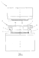
- Figure 1 is as partly sectional view of the mould of the invention associated with a press.
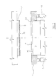
- Figure 2 is an enlarged view of a part of Figure 1.
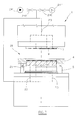
- Figure 3 is a partly sectional view of a variant of the mould of the invention associated with a press.
- Figure 1 shows a press 1, on which a mould 2 of the movable die plate type is installed.
- the mould 2 comprises a movable lower die 3 rigid with the lower crosspiece of the press 1 and partly inserted into a laterally containing die plate 4.
- Said die plate 4 rests on the bed of the press 1 via elastic elements 5.
- the upper surface 30 of the die 3 and the inner walls 40 of the die plate define the mould forming cavity 6 in which the powders to be compacted are deposited by known means, not shown.
- the press 1 supports the upper die 7, which is fixed to the movable upper crosspiece of the press 1.
- the outer dimensions of the upper die 7 are virtually identical to those of the lower die and such as to enable it to be inserted into the die plate 4 to enable the material contained in the forming cavity 6 to be pressed.
- the upper surface 30 of the die 3 is provided with a layer 8 of air-permeable porous material.
- the layer 8 can be formed from sintered metals, sintered plastic or porous resins.
- the layer 8 consists of rigid porous resins having 10-50% of open total porosity (by volume) and a thickness of 5-30 mm.
- the mean pore diameter of the porous resin varies between 1 and 50 ⁇ m on the basis of the material with which the layer is constructed and the size of the atomized powder particles used in the forming process.
- composition of a porous resin suitable for the purpose is fully described in patent applications EP 165952 and EP 516224 of the same applicant and comprises the following components:
- the thickness of said layer 8 varies as a function of the open total porosity, and of the dimensions of the slab to be formed.
- the mean pore diameter influences the tile surface quality, i.e. its roughness, in that a decrease in mean pore diameter of the layer 8 results in lesser tile surface roughness.
- the perimetral edge of the layer can be provided with a perimetral frame not shown, of non-porous material.
- said perimetral frame can be made from a suitable impermeable varnish, or by metal edging applied to the perimetral edge of the layer 8. In this latter case said metal edging can be rigid with the die to which the layer 8 is fixed.
- said layer 8 is connected to suitable means for feeding a pressurized fluid, for example compressed air, these means feeding air through the pores of said layer on termination of the pressing cycle, to expel any powder particles which may be trapped within the pores.
- a pressurized fluid for example compressed air
- FIG. 3 shows a variant of the invention.
- the description of this variant uses the same reference numerals to indicate components identical to those previously described.
- FIG. 1 shows the press 1 on which a mould 20 of movable die plate type is installed.
- the mould 20 comprises a lower die 21 partly inserted into a movable die plate 4.
- the inner lateral walls of the die plate 4 and the surface of the lower die 21 define the mould cavity 6, in which the powder mass to be pressed is deposited.
- the upper crosspiece of the press 1 supports the upper die 7 above the lower die 21.
- both press dies are faced with a layer 8 of porous material, in particular resin, the purpose of which as previously described is to absorb, during the pressing action, the mass of air contained within the powders to be pressed.
- the air-permeable layer 8 is connected to a plurality of air discharge channels 23 which are provided within the two dies 3 and 7 and have one end opening into the die surfaces, their other end being connected to a suitable air feed device 24' and a suitable air suction device 24", valve elements 240 being interposed between said devices and said layers.
- said device 24" creates a vacuum within the layers 8 in order to accelerate air evacuation from the powder mass to be pressed.
- the device 24' feeds compressed air through the layers 8 to eliminate any powder particles which have remained trapped within the layer pores.
- said air-permeable porous material layer 8 can constitute a facing of the entire die surface or of only a portion thereof.
Landscapes
- Engineering & Computer Science (AREA)
- Mechanical Engineering (AREA)
- Manufacturing & Machinery (AREA)
- Chemical & Material Sciences (AREA)
- Ceramic Engineering (AREA)
- Press-Shaping Or Shaping Using Conveyers (AREA)
- Finishing Walls (AREA)
- Moulds For Moulding Plastics Or The Like (AREA)
Abstract
Description
- acrylic monomers
- styrene monomers
- unsaturated polyester resins
- acrylic resins
Claims (18)
- A ceramic tile pressing mould comprising a lower die, an upper die, and a laterally containing die plate which together with said lower die defines the mould cavity in which the powders to be compacted are deposited, characterised in that at least one portion of the working surface of one of the dies comprises a layer of porous material able to receive the air present in said powders.
- A mould as claimed in claim 1, characterised in that said porous material layer is rigid.
- A mould as claimed in claim 1, characterised in that said porous layer is connected to atmosphere via at least one discharge channel.
- A mould as claimed in claim 1, characterised in that said surface layer is connected to suction means.
- A mould as claimed in claim 1, characterised in that said surface layer is connected to air feed means.
- A mould as claimed in claim 5, characterised in that said means comprise at least one compressed air feed device, at least one suction device and suitable valve elements.
- A mould as claimed in claim 5, characterised in that said means comprise at least one air suction device and suitable valve elements.
- A mould as claimed in claim 1, characterised in that said porous material layer is a microporous resin.
- A mould as claimed in claim 1, characterised in that said microporous resin layer preferably comprises at least the following components: acrylic monomers, acrylic resins.
- A mould as claimed in claim 1, characterised in that the open total porosity of said resin is between 10% and 50% by volume.
- A mould as claimed in claim 1, characterised in that the mean pore diameter of said resin layer varies between 1 and 50 µm.
- A mould as claimed in claim 1, characterised in that said porous material layer consists of sintered metals.
- A mould as claimed in claim 1, characterised in that said porous material layer consists of sintered synthetic resin.
- A mould as claimed in claim 1, characterised in that said layer is provided with a perimetral frame of non-porous material.
- A mould as claimed in claim 14, characterised in that said perimetral frame is formed from impermeabilizing varnish.
- A mould as claimed in claim 14, characterised in that said frame is of steel.
- A mould as claimed in claim 14, characterised in that said perimetral frame is rigid with the edge of the die with which said layer is associated.
- A die for a ceramic powder pressing mould, characterised by presenting at least one of the characteristics stated in claims from 1 to 17.
Applications Claiming Priority (2)
| Application Number | Priority Date | Filing Date | Title |
|---|---|---|---|
| IT2001RE000080A ITRE20010080A1 (en) | 2001-07-30 | 2001-07-30 | MOLD FOR PRESSING CERAMIC TILES, IN PARTICULAR OF LARGE SHEETS |
| ITRE20010080 | 2001-07-30 |
Publications (2)
| Publication Number | Publication Date |
|---|---|
| EP1281494A2 true EP1281494A2 (en) | 2003-02-05 |
| EP1281494A3 EP1281494A3 (en) | 2003-11-19 |
Family
ID=11454138
Family Applications (1)
| Application Number | Title | Priority Date | Filing Date |
|---|---|---|---|
| EP02077662A Withdrawn EP1281494A3 (en) | 2001-07-30 | 2002-07-04 | Mould for pressing ceramic tiles, in particular large-dimension slabs |
Country Status (2)
| Country | Link |
|---|---|
| EP (1) | EP1281494A3 (en) |
| IT (1) | ITRE20010080A1 (en) |
Cited By (11)
| Publication number | Priority date | Publication date | Assignee | Title |
|---|---|---|---|---|
| CN102441937A (en) * | 2011-12-01 | 2012-05-09 | 周文鹏 | Ceramic tile molding die capable of preventing vent holes from being blocked |
| CN103434006A (en) * | 2013-08-13 | 2013-12-11 | 上海高诚艺术包装有限公司 | Device for forming body of large-sized ceramic dish utensil and use method of device |
| CN103753696A (en) * | 2014-01-27 | 2014-04-30 | 龚小乙 | Exhaust type pressure-equalizing ceramic tile forming die |
| CN105082328A (en) * | 2014-05-20 | 2015-11-25 | 上海斯米克控股股份有限公司 | Vitrified brick molding device with stereoscopic fluctuating face |
| CN105108893A (en) * | 2015-09-11 | 2015-12-02 | 福建海源自动化机械股份有限公司 | Device for discharging ash on lower oblique surface of mould of brick machine |
| CN105128140A (en) * | 2015-09-30 | 2015-12-09 | 佛山市新鹏工业服务有限公司 | Gas exhaust mould special for pressing ceramic tile |
| CN105150368A (en) * | 2015-09-11 | 2015-12-16 | 福建海源自动化机械股份有限公司 | Lower mold screw ash discharging device for brick pressing machine mold |
| CN105235251A (en) * | 2015-10-22 | 2016-01-13 | 昆山鸿志犀自动化机电设备有限公司 | Online control hot press |
| IT201700076893A1 (en) * | 2017-07-07 | 2019-01-07 | Sacmi | APPARATUS AND METHOD FOR THE PRODUCTION OF CERAMIC PRODUCTS |
| CN109822735A (en) * | 2019-03-27 | 2019-05-31 | 绵阳中正科技有限公司 | Lightweight partition board and preparation method thereof |
| DE102022109855A1 (en) | 2022-04-25 | 2023-10-26 | Kobra Formen Gmbh | Device for producing concrete blocks and method for producing concrete blocks |
Family Cites Families (3)
| Publication number | Priority date | Publication date | Assignee | Title |
|---|---|---|---|---|
| JPS5837361B2 (en) * | 1981-06-02 | 1983-08-16 | 株式会社 ヨシツカ精機 | Vacuum powder molding method |
| GB9617817D0 (en) * | 1996-08-27 | 1996-10-09 | Tadion Jamal | Evacuable KBr die |
| US6482349B1 (en) * | 1998-11-02 | 2002-11-19 | Sumitomo Special Metals Co., Ltd. | Powder pressing apparatus and powder pressing method |
-
2001
- 2001-07-30 IT IT2001RE000080A patent/ITRE20010080A1/en unknown
-
2002
- 2002-07-04 EP EP02077662A patent/EP1281494A3/en not_active Withdrawn
Cited By (17)
| Publication number | Priority date | Publication date | Assignee | Title |
|---|---|---|---|---|
| CN102441937A (en) * | 2011-12-01 | 2012-05-09 | 周文鹏 | Ceramic tile molding die capable of preventing vent holes from being blocked |
| CN103434006A (en) * | 2013-08-13 | 2013-12-11 | 上海高诚艺术包装有限公司 | Device for forming body of large-sized ceramic dish utensil and use method of device |
| CN103753696A (en) * | 2014-01-27 | 2014-04-30 | 龚小乙 | Exhaust type pressure-equalizing ceramic tile forming die |
| CN105082328B (en) * | 2014-05-20 | 2017-12-01 | 上海悦心健康集团股份有限公司 | A kind of three-dimensional relief vitrified tile shaped device |
| CN105082328A (en) * | 2014-05-20 | 2015-11-25 | 上海斯米克控股股份有限公司 | Vitrified brick molding device with stereoscopic fluctuating face |
| CN105108893A (en) * | 2015-09-11 | 2015-12-02 | 福建海源自动化机械股份有限公司 | Device for discharging ash on lower oblique surface of mould of brick machine |
| CN105150368A (en) * | 2015-09-11 | 2015-12-16 | 福建海源自动化机械股份有限公司 | Lower mold screw ash discharging device for brick pressing machine mold |
| CN105150368B (en) * | 2015-09-11 | 2018-05-08 | 福建海源自动化机械股份有限公司 | Brick press die lower die screw rod ash exhauster |
| CN105108893B (en) * | 2015-09-11 | 2018-05-08 | 福建海源自动化机械股份有限公司 | Brick press die lower die inclined-plane ash exhauster |
| CN105128140A (en) * | 2015-09-30 | 2015-12-09 | 佛山市新鹏工业服务有限公司 | Gas exhaust mould special for pressing ceramic tile |
| CN105235251A (en) * | 2015-10-22 | 2016-01-13 | 昆山鸿志犀自动化机电设备有限公司 | Online control hot press |
| IT201700076893A1 (en) * | 2017-07-07 | 2019-01-07 | Sacmi | APPARATUS AND METHOD FOR THE PRODUCTION OF CERAMIC PRODUCTS |
| EP3424659A1 (en) * | 2017-07-07 | 2019-01-09 | Sacmi Cooperativa Meccanici Imola Societa' Cooperativa | Apparatus and method for manufacturing ceramic products |
| CN109822735A (en) * | 2019-03-27 | 2019-05-31 | 绵阳中正科技有限公司 | Lightweight partition board and preparation method thereof |
| CN109822735B (en) * | 2019-03-27 | 2021-04-30 | 绵阳中正科技有限公司 | Light partition board and preparation method thereof |
| DE102022109855A1 (en) | 2022-04-25 | 2023-10-26 | Kobra Formen Gmbh | Device for producing concrete blocks and method for producing concrete blocks |
| WO2023208857A1 (en) | 2022-04-25 | 2023-11-02 | Kobra Formen Gmbh | Device for producing molded concrete blocks, and method for producing molded concrete blocks |
Also Published As
| Publication number | Publication date |
|---|---|
| ITRE20010080A1 (en) | 2003-01-30 |
| ITRE20010080A0 (en) | 2001-07-30 |
| EP1281494A3 (en) | 2003-11-19 |
Similar Documents
| Publication | Publication Date | Title |
|---|---|---|
| EP0894587B1 (en) | Method for pressing ceramic powders, and equipment for its implementation | |
| KR101882546B1 (en) | Apparatuses, system and methods for forming pressed articles and pressed articles formed thereby | |
| JPH06128900A (en) | Forming mold for formed fiber, forming method, forming apparatus and formed fiber article | |
| US6030576A (en) | Method for forming ceramic tiles by means of partially isostatic moulds | |
| CA2350546A1 (en) | Method for making a sintered article and products produced thereby | |
| US3737276A (en) | Molding of powdered or granular material | |
| ITRE20010080A1 (en) | MOLD FOR PRESSING CERAMIC TILES, IN PARTICULAR OF LARGE SHEETS | |
| US20110100522A1 (en) | Cold press and method for the production of green compacts | |
| EP1106336B1 (en) | An apparatus for removing air from soft powder material in a press-forming cycle for manufacture of ceramic products | |
| US3705248A (en) | Molding of powdered or granular material | |
| JPS61176515A (en) | Method for forming powdery solid cosmetic and apparatus therefor | |
| EP1266733B1 (en) | Method and plant for forming large-dimension ceramic slabs and tiles | |
| JPH09327812A (en) | Wet press molding method and apparatus | |
| RU2147520C1 (en) | Apparatus for pressing powdered materials | |
| KR20090087068A (en) | Filling and Compression Method of Filling Shoe and Powder | |
| EP0569069A1 (en) | Ceramic mold for forming tiles, and the relative loading means | |
| ITBO970080A1 (en) | PROCEDURE FOR THE TRANSFER OF CERAMIC POWDER FROM A SAMPLING AREA TO AN USE AREA. | |
| JP3145202U (en) | Suction support device | |
| JPH0432250Y2 (en) | ||
| JP3145202U7 (en) | ||
| EP3424659A1 (en) | Apparatus and method for manufacturing ceramic products | |
| EP0626242A1 (en) | Device for manufacturing bricks | |
| WO2025088650A1 (en) | Compacting assembly for ceramic products | |
| JP2712894B2 (en) | Method of forming fine pieces | |
| JPS636181Y2 (en) |
Legal Events
| Date | Code | Title | Description |
|---|---|---|---|
| PUAI | Public reference made under article 153(3) epc to a published international application that has entered the european phase |
Free format text: ORIGINAL CODE: 0009012 |
|
| AK | Designated contracting states |
Designated state(s): AT BE BG CH CY CZ DE DK EE ES FI FR GB GR IE IT LI LU MC NL PT SE SK TR |
|
| AX | Request for extension of the european patent |
Extension state: AL LT LV MK RO SI |
|
| PUAL | Search report despatched |
Free format text: ORIGINAL CODE: 0009013 |
|
| AK | Designated contracting states |
Kind code of ref document: A3 Designated state(s): AT BE BG CH CY CZ DE DK EE ES FI FR GB GR IE IT LI LU MC NL PT SE SK TR |
|
| AX | Request for extension of the european patent |
Extension state: AL LT LV MK RO SI |
|
| 17P | Request for examination filed |
Effective date: 20040422 |
|
| AKX | Designation fees paid |
Designated state(s): DE ES IT TR |
|
| RAP1 | Party data changed (applicant data changed or rights of an application transferred) |
Owner name: SACMI COOPERATIVA MECCANICI IMOLA SOCIETA' COOPERA |
|
| 17Q | First examination report despatched |
Effective date: 20071017 |
|
| STAA | Information on the status of an ep patent application or granted ep patent |
Free format text: STATUS: THE APPLICATION IS DEEMED TO BE WITHDRAWN |
|
| 18D | Application deemed to be withdrawn |
Effective date: 20100202 |