EP1279865A2 - Jackscrew apparatus - Google Patents
Jackscrew apparatus Download PDFInfo
- Publication number
- EP1279865A2 EP1279865A2 EP02077700A EP02077700A EP1279865A2 EP 1279865 A2 EP1279865 A2 EP 1279865A2 EP 02077700 A EP02077700 A EP 02077700A EP 02077700 A EP02077700 A EP 02077700A EP 1279865 A2 EP1279865 A2 EP 1279865A2
- Authority
- EP
- European Patent Office
- Prior art keywords
- screw
- gear
- nut
- motion
- rotational
- Prior art date
- Legal status (The legal status is an assumption and is not a legal conclusion. Google has not performed a legal analysis and makes no representation as to the accuracy of the status listed.)
- Withdrawn
Links
- 230000002441 reversible effect Effects 0.000 claims description 8
Images

Classifications
-
- H—ELECTRICITY
- H02—GENERATION; CONVERSION OR DISTRIBUTION OF ELECTRIC POWER
- H02K—DYNAMO-ELECTRIC MACHINES
- H02K7/00—Arrangements for handling mechanical energy structurally associated with dynamo-electric machines, e.g. structural association with mechanical driving motors or auxiliary dynamo-electric machines
- H02K7/06—Means for converting reciprocating motion into rotary motion or vice versa
-
- E—FIXED CONSTRUCTIONS
- E05—LOCKS; KEYS; WINDOW OR DOOR FITTINGS; SAFES
- E05C—BOLTS OR FASTENING DEVICES FOR WINGS, SPECIALLY FOR DOORS OR WINDOWS
- E05C3/00—Fastening devices with bolts moving pivotally or rotatively
- E05C3/12—Fastening devices with bolts moving pivotally or rotatively with latching action
- E05C3/16—Fastening devices with bolts moving pivotally or rotatively with latching action with operating handle or equivalent member moving otherwise than rigidly with the latch
-
- F—MECHANICAL ENGINEERING; LIGHTING; HEATING; WEAPONS; BLASTING
- F16—ENGINEERING ELEMENTS AND UNITS; GENERAL MEASURES FOR PRODUCING AND MAINTAINING EFFECTIVE FUNCTIONING OF MACHINES OR INSTALLATIONS; THERMAL INSULATION IN GENERAL
- F16H—GEARING
- F16H25/00—Gearings comprising primarily only cams, cam-followers and screw-and-nut mechanisms
- F16H25/18—Gearings comprising primarily only cams, cam-followers and screw-and-nut mechanisms for conveying or interconverting oscillating or reciprocating motions
- F16H25/20—Screw mechanisms
-
- Y—GENERAL TAGGING OF NEW TECHNOLOGICAL DEVELOPMENTS; GENERAL TAGGING OF CROSS-SECTIONAL TECHNOLOGIES SPANNING OVER SEVERAL SECTIONS OF THE IPC; TECHNICAL SUBJECTS COVERED BY FORMER USPC CROSS-REFERENCE ART COLLECTIONS [XRACs] AND DIGESTS
- Y10—TECHNICAL SUBJECTS COVERED BY FORMER USPC
- Y10T—TECHNICAL SUBJECTS COVERED BY FORMER US CLASSIFICATION
- Y10T74/00—Machine element or mechanism
- Y10T74/18—Mechanical movements
- Y10T74/18568—Reciprocating or oscillating to or from alternating rotary
- Y10T74/18576—Reciprocating or oscillating to or from alternating rotary including screw and nut
Definitions
- This invention relates generally to a jackscrew apparatus for converting reciprocal rotational motion into reciprocal linear motion.
- a jackscrew apparatus prefferably includes a lock block or nut slidably supported in a cradle for reciprocal translational motion and against rotational motion and a screw that threadedly and drivingly engages the nut. It is also known to fabricate a spur gear on one end of the screw that rotates the screw when driven by a reversible electric motor through a reduction gear set.
- United States Patent No. 6,019,402 issued 1 February, 2000 to Arabia, Jr. et al., discloses a vehicle door latch including a jackscrew apparatus. The Arabia Jr. et al.
- jackscrew apparatus includes a lock block slidably supported in a cradle for reciprocal translational motion and against rotational motion.
- a screw threadedly and drivingly engages the nut.
- a spur gear is supported on the screw and rotates the screw when driven by a reversible electric motor through a reduction gear set.
- a jackscrew apparatus constructed according to the Arabia, Jr. et al. is not constructed to facilitate the use a relatively small, low-torque electric motor to drive a high-output gearbox.
- What is needed is a jackscrew apparatus that can use a relatively small, low-torque electric motor to drive a high-output gearbox.
- the invention is a jackscrew apparatus for converting reciprocal rotational motion into reciprocal linear motion.
- the apparatus includes a nut supported for reciprocal translational motion and against rotational motion and a screw threadedly and drivingly engaging the nut.
- the jackscrew apparatus also includes a motor drivingly connected to the screw and configured to reversibly rotate the screw about a longitudinal screw axis to drive the nut through its reciprocal translational motion.
- the jackscrew apparatus also includes a lost motion drive linkage connected between the motor and the nut and configured to allow lost rotational motion between the motor and the nut to allow the motor to accelerate before bearing the load of rotating the screw and driving the translational motion of the nut. Therefore, a jackscrew apparatus constructed according to the invention allows for the use of a relatively small, low-torque electric motor to drive a high-output gearbox.
- a jackscrew apparatus for converting reciprocal rotational motion into reciprocal linear motion is shown at 10 in the Figures.
- the apparatus 10 includes a nut 12 supported for reciprocal translational motion and against rotational motion.
- a screw 14 threadedly and drivingly engages the nut 12.
- the apparatus 10 also includes a motor 16 drivingly connected to the screw 14 and configured to reversibly rotate the screw 14 about a longitudinal screw axis 18 to drive the nut 12 through its reciprocal translational motion.
- the apparatus 10 also includes a lost motion drive linkage 20 connected between the motor 16 and the nut 12.
- the lost motion drive linkage 20 allows lost rotational motion between the motor 16 and the nut 12. This allows the motor 16 to accelerate before bearing the load of rotating the screw 14 and driving the translational motion of the nut 12.
- the lost motion drive linkage 20 allows lost rotational motion between the motor 16, which is a reversible electric motor, and the nut 12 in both directions of screw rotation. This allows the motor 16 to accelerate before driving the nut 12 in either direction.
- the lost motion drive linkage 20 includes a reduction gear linkage.
- the reduction gear linkage includes a motor pinion gear 22 fixed to an output armature shaft 24 of the motor 16.
- the motor pinion gear 22 drivingly engages a driven spur gear 25 carried on the screw 14 for lost motion rotational travel relative to the screw 14 about the screw axis 18, i.e., without rotating the screw 14.
- the driven spur gear 25 is also supported on the screw 14 for rotational engagement with the screw 14 at a first end of the lost motion travel of the driven gear.
- the driven gear 25 is also supported on the screw 14 for rotational engagement with the screw 14 at a second end of the lost motion travel of the driven gear.
- the screw 14 includes a first screw detent surface 26 and the driven gear 25 includes a first gear detent surface 28 rotationally aligned with and positioned to engage the first screw detent surface 26 when the gear reaches the first end of its rotational lost motion travel.
- the driven gear 25 reaches the first end of its rotational lost motion travel the first gear detent surface 28 engages the first screw detent surface 26 allowing the driven gear 25 to begin rotating the screw 14 in the direction to advance the nut 12 along the screw 14 away from the driven gear.
- the screw 14 includes a second screw detent surface 30 and the driven gear 25 includes a second gear detent surface 32 rotationally aligned with and positioned to engage the second screw detent surface 30 when the gear reaches the second end of its rotational lost motion travel.
- the driven gear 25 causes the second gear detent surface 32 to engage the second screw detent surface 30
- continued rotation of the driven gear 25 causes the screw 14 to rotate in a direction to retract the nut 12 along the screw 14 toward the driven gear.
- the first and second screw detent surfaces are disposed on rotationally opposite sides of a screw tab 34 that extends radially and integrally outward from a main shaft 36 of the screw 14.
- This screw tab 34 abuts an annular flange 38 that also extends radially outward from around the main shaft 36.
- the annular flange 38 separates a threaded portion 40 of the screw 14 from a non-threaded portion 42 of the screw 14.
- the first and second gear detent surfaces are disposed on rotationally opposite sides of a gear tab 44 that extends axially and integrally from a main body 46 of the driven gear.
- the gear tab 44 extends from the main body 46 of the driven gear 25 in a position to rotationally align the first and second gear detent surfaces with the respective first and second screw detent surfaces when the driven gear 25 is seated on the non-threaded portion of the main shaft 36 of the screw 14.
- the nut 12 includes a pair of pair of parallel slides that are integrally formed with a main body 49 of the nut 12.
- the slides are aligned with the screw axis 18 and help to guide the nut 12 along an adjacent surface (also parallel to the screw axis 18) while preventing the nut 12 from rotating as the screw 14 moves the nut 12 along its reciprocal linear path.
- a drive peg 52 integrally and radially extends from the nut 12 in a position to engage a mechanism (not shown) to be driven by the jackscrew.
- the drive peg 52 also helps to support the nut 12 against rotation.
- the motor 16 is first actuated and begins to accelerate to its full free speed. As the motor 16 accelerates, the output armature shaft 24 of the motor 16 turns the motor pinion gear 22 which turns the driven spur gear 25. For the first approximate 300 degrees of driven gear rotation, the screw 14 does not turn because the gear tab 44 has not yet brought the first gear detent surface 28 into contact with the first screw detent surface 26. Once the first approximate 300 degrees of driven gear rotation are complete, the gear tabs meets the screw tab 34 causing the screw 14 to begin rotating and pushing the nut 12 axially away from the annular flange 38. Once the nut 12 reaches the end of its travel, the motor 16 is de-energized leaving the gear tab 44 in contact with the screw tab 34.
- the motor 16 When the time comes that the motor 16 is actuated in a reverse direction to retract the nut 12, the motor 16 first accelerates to its full free sped while turning the motor pinion gear 22 which turns the driven spur gear in a direction opposite the direction it was turned to advance the nut 12. Because of the gear tab 44 of the driven gear 25 began in a position contacting the screw tab 34, the gear is able to rotate through an approximate 300 degrees of rotation before bringing the second gear detent surface 32 of the gear tab 44 into contact with the second screw detent surface 30 of the screw tab 34.
- the driven gear will begin rotating the screw 14 and retracting the nut 12.
- the motor 16 is de-energized with the second gear detent surface 32 remaining in contact with the second screw detent surface 30.
- the gear tab 44 will again have an approximate 300 degrees of rotation before contacting the screw tab 34.
- a jackscrew apparatus constructed according to the invention will allow a relatively small, low torque electric motor 16 to drive a high output gear box. This is because the lost motion feature of the reduction gear linkage allows the motor 16 to accelerate to its full free speed before starting to rotate the screw 14. This allows the motor 16 to overcome nut 12 driving loads that would otherwise exceed a normal stall torque of the motor 16.
Landscapes
- Engineering & Computer Science (AREA)
- General Engineering & Computer Science (AREA)
- Mechanical Engineering (AREA)
- Power Engineering (AREA)
- Transmission Devices (AREA)
Abstract
Description
- This invention relates generally to a jackscrew apparatus for converting reciprocal rotational motion into reciprocal linear motion.
- It is known for a jackscrew apparatus to include a lock block or nut slidably supported in a cradle for reciprocal translational motion and against rotational motion and a screw that threadedly and drivingly engages the nut. It is also known to fabricate a spur gear on one end of the screw that rotates the screw when driven by a reversible electric motor through a reduction gear set. For example, United States Patent No. 6,019,402 issued 1 February, 2000 to Arabia, Jr. et al., discloses a vehicle door latch including a jackscrew apparatus. The Arabia Jr. et al. jackscrew apparatus includes a lock block slidably supported in a cradle for reciprocal translational motion and against rotational motion. A screw threadedly and drivingly engages the nut. A spur gear is supported on the screw and rotates the screw when driven by a reversible electric motor through a reduction gear set. However, a jackscrew apparatus constructed according to the Arabia, Jr. et al. is not constructed to facilitate the use a relatively small, low-torque electric motor to drive a high-output gearbox.
- What is needed is a jackscrew apparatus that can use a relatively small, low-torque electric motor to drive a high-output gearbox.
- The invention is a jackscrew apparatus for converting reciprocal rotational motion into reciprocal linear motion. The apparatus includes a nut supported for reciprocal translational motion and against rotational motion and a screw threadedly and drivingly engaging the nut. The jackscrew apparatus also includes a motor drivingly connected to the screw and configured to reversibly rotate the screw about a longitudinal screw axis to drive the nut through its reciprocal translational motion.
- Unlike the prior art of record, the jackscrew apparatus also includes a lost motion drive linkage connected between the motor and the nut and configured to allow lost rotational motion between the motor and the nut to allow the motor to accelerate before bearing the load of rotating the screw and driving the translational motion of the nut. Therefore, a jackscrew apparatus constructed according to the invention allows for the use of a relatively small, low-torque electric motor to drive a high-output gearbox.
- These and other features and advantages of the invention will become apparent to those skilled in the art in connection with the following detailed description and drawings, in which:
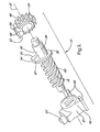
- FIG. 1 is a front view of a jackscrew apparatus constructed according to the invention and installed in an automobile door latch;
- FIG. 2 is a perspective view of a driven gear of the jackscrew apparatus of FIG. 1 carried on a screw of the apparatus with a nut of the apparatus shown axially displaced for clarity; and
- FIG. 3 is a perspective exploded view of the screw, nut and driven gear of FIG. 2.
- A jackscrew apparatus for converting reciprocal rotational motion into reciprocal linear motion is shown at 10 in the Figures. The
apparatus 10 includes anut 12 supported for reciprocal translational motion and against rotational motion. Ascrew 14 threadedly and drivingly engages thenut 12. Theapparatus 10 also includes amotor 16 drivingly connected to thescrew 14 and configured to reversibly rotate thescrew 14 about alongitudinal screw axis 18 to drive thenut 12 through its reciprocal translational motion. Theapparatus 10 also includes a lostmotion drive linkage 20 connected between themotor 16 and thenut 12. The lostmotion drive linkage 20 allows lost rotational motion between themotor 16 and thenut 12. This allows themotor 16 to accelerate before bearing the load of rotating thescrew 14 and driving the translational motion of thenut 12. - The lost
motion drive linkage 20 allows lost rotational motion between themotor 16, which is a reversible electric motor, and thenut 12 in both directions of screw rotation. This allows themotor 16 to accelerate before driving thenut 12 in either direction. - As best shown in Fig. 1, the lost
motion drive linkage 20 includes a reduction gear linkage. The reduction gear linkage includes amotor pinion gear 22 fixed to anoutput armature shaft 24 of themotor 16. Themotor pinion gear 22 drivingly engages a driven spur gear 25 carried on thescrew 14 for lost motion rotational travel relative to thescrew 14 about thescrew axis 18, i.e., without rotating thescrew 14. The driven spur gear 25 is also supported on thescrew 14 for rotational engagement with thescrew 14 at a first end of the lost motion travel of the driven gear. The driven gear 25 is also supported on thescrew 14 for rotational engagement with thescrew 14 at a second end of the lost motion travel of the driven gear. - As best shown in Fig. 3, the
screw 14 includes a first screwdetent surface 26 and the driven gear 25 includes a first geardetent surface 28 rotationally aligned with and positioned to engage the first screwdetent surface 26 when the gear reaches the first end of its rotational lost motion travel. When the driven gear 25 reaches the first end of its rotational lost motion travel the first geardetent surface 28 engages the first screwdetent surface 26 allowing the driven gear 25 to begin rotating thescrew 14 in the direction to advance thenut 12 along thescrew 14 away from the driven gear. - As best shown in Figs. 1 and 2, the
screw 14 includes a second screwdetent surface 30 and the driven gear 25 includes a second geardetent surface 32 rotationally aligned with and positioned to engage the second screwdetent surface 30 when the gear reaches the second end of its rotational lost motion travel. When rotation of the driven gear 25 causes the second geardetent surface 32 to engage the second screwdetent surface 30, continued rotation of the driven gear 25 causes thescrew 14 to rotate in a direction to retract thenut 12 along thescrew 14 toward the driven gear. - The first and second screw detent surfaces are disposed on rotationally opposite sides of a
screw tab 34 that extends radially and integrally outward from amain shaft 36 of thescrew 14. Thisscrew tab 34 abuts anannular flange 38 that also extends radially outward from around themain shaft 36. Theannular flange 38 separates a threadedportion 40 of thescrew 14 from a non-threadedportion 42 of thescrew 14. The first and second gear detent surfaces are disposed on rotationally opposite sides of agear tab 44 that extends axially and integrally from amain body 46 of the driven gear. Thegear tab 44 extends from themain body 46 of the driven gear 25 in a position to rotationally align the first and second gear detent surfaces with the respective first and second screw detent surfaces when the driven gear 25 is seated on the non-threaded portion of themain shaft 36 of thescrew 14. - The
nut 12 includes a pair of pair of parallel slides that are integrally formed with amain body 49 of thenut 12. The slides are aligned with thescrew axis 18 and help to guide thenut 12 along an adjacent surface (also parallel to the screw axis 18) while preventing thenut 12 from rotating as thescrew 14 moves thenut 12 along its reciprocal linear path. - A drive peg 52 integrally and radially extends from the
nut 12 in a position to engage a mechanism (not shown) to be driven by the jackscrew. Thedrive peg 52 also helps to support thenut 12 against rotation. - In practice, to operate the jackscrew, the
motor 16 is first actuated and begins to accelerate to its full free speed. As themotor 16 accelerates, theoutput armature shaft 24 of themotor 16 turns themotor pinion gear 22 which turns the driven spur gear 25. For the first approximate 300 degrees of driven gear rotation, thescrew 14 does not turn because thegear tab 44 has not yet brought the first gear detentsurface 28 into contact with the first screwdetent surface 26. Once the first approximate 300 degrees of driven gear rotation are complete, the gear tabs meets thescrew tab 34 causing thescrew 14 to begin rotating and pushing thenut 12 axially away from theannular flange 38. Once thenut 12 reaches the end of its travel, themotor 16 is de-energized leaving thegear tab 44 in contact with thescrew tab 34. - When the time comes that the
motor 16 is actuated in a reverse direction to retract thenut 12, themotor 16 first accelerates to its full free sped while turning themotor pinion gear 22 which turns the driven spur gear in a direction opposite the direction it was turned to advance thenut 12. Because of thegear tab 44 of the driven gear 25 began in a position contacting thescrew tab 34, the gear is able to rotate through an approximate 300 degrees of rotation before bringing the second geardetent surface 32 of thegear tab 44 into contact with the second screwdetent surface 30 of thescrew tab 34. Once themotor 16 has reached, in reverse, its full free speed and has turned the driven gear 25 through its first 300 degrees of reverse rotation, and thegear tab 44 has once again contacted thescrew tab 34, the driven gear will begin rotating thescrew 14 and retracting thenut 12. Once thenut 12 reaches a home position abutting theannular flange 38 themotor 16 is de-energized with the second geardetent surface 32 remaining in contact with the second screwdetent surface 30. As such, whenever themotor 16 is again energized to advance thenut 12 along thescrew 14, thegear tab 44 will again have an approximate 300 degrees of rotation before contacting thescrew tab 34. - As such, a jackscrew apparatus constructed according to the invention will allow a relatively small, low torque
electric motor 16 to drive a high output gear box. This is because the lost motion feature of the reduction gear linkage allows themotor 16 to accelerate to its full free speed before starting to rotate thescrew 14. This allows themotor 16 to overcomenut 12 driving loads that would otherwise exceed a normal stall torque of themotor 16. - This description is intended to illustrate certain embodiments of the invention rather than to limit the invention. Therefore, it uses descriptive rather than limiting words. Obviously, it's possible to modify this invention from what the description teaches. Within the scope of the claims, one may practice the invention other than as described.
Claims (13)
- A jackscrew apparatus (10) for converting reciprocal rotational motion into reciprocal linear motion, the apparatus (10) comprising:a nut (12) supported for reciprocal translational motion and against rotational motion;a screw (14) threadedly and drivingly engaging the nut (12);a motor (16) drivingly connected to the screw (14) and configured to reversibly rotate the screw (14) about a longitudinal screw axis (18) to drive the nut (12) through its reciprocal translational motion; anda lost motion drive linkage (20) connected between the motor (16) and the nut (12) and configured to allow lost rotational motion between the motor (16) and the nut (12) to allow the motor to accelerate before bearing the load of rotating the screw (14) and driving the translational motion of the nut (12).
- A jackscrew apparatus (10) as defined in claim 1 in which the lost motion drive linkage (20) is configured to allow lost rotational motion between the motor (16) and nut (12) in at least one direction of screw rotation.
- A jackscrew apparatus (10) as defined in claim 2 in which the lost motion drive linkage (20) includes a gear linkage including a driven gear supported on the screw (14) for lost motion rotational travel relative to the screw (14) about the screw axis (18) and for rotational engagement with the screw (14) at a first end of the lost motion travel of the driven gear.
- A jackscrew apparatus (10) as defined in claim 3 in which the driven gear is supported on the screw (14) for rotational engagement with the screw (14) at a second end of the lost motion travel of the driven gear.
- A jackscrew apparatus (10) as defined in claim 4 in which:the screw (14) includes a first screw detent (26); andthe driven gear includes a first gear detent (28) rotationally aligned with and positioned to engage the first screw detent (26) when the gear reaches the first end of its rotational lost motion travel to begin rotating the screw (14) in a direction to advance the nut (12) along the screw (14).
- A jackscrew apparatus (10) as defined in claim 5 in which:the screw (14) includes a second screw detent (30); andthe driven gear includes a second gear detent (32) rotationally aligned with and positioned to engage the second screw detent (30) when the gear reaches the second end of its rotational lost motion travel to begin rotating the screw (14) in a direction to retract the nut (12) along the screw (14).
- A jackscrew apparatus (10) as defined in claim 6 in which:the first and second screw detents are disposed on a screw tab (34) extending radially outward from a main shaft (36) of the screw (14); andthe first and second gear detents are disposed on a gear tab (44) that extends axially from a main body (46) of the driven gear in a position to rotationally align the first and second gear detents with the respective first and second screw detents when the driven gear is seated on the main shaft (36) of the screw (14).
- A jackscrew apparatus (10) as defined in claim 3 in which the gear linkage (20) is a reduction gear linkage.
- A jackscrew apparatus (10) as defined in claim 1 in which the motor (16) is a reversible electric motor.
- A jackscrew apparatus (10) for converting reciprocal rotational motion into reciprocal linear motion, the apparatus (10) comprising:a nut (12) supported for reciprocal translational motion and against rotational motion;a screw (14) threadedly and drivingly engaging the nut (12);a reversible electric motor (16) drivingly connected to the screw (14) and configured to reversibly rotate the screw (14) about a longitudinalscrew axis (18) to drive the nut (12) through its reciprocal translational motion; anda gear linkage (20) connected between the motor (16) and the screw (14) and including a driven gear supported on the screw (14) for lost motion rotational travel relative to the screw (14) about the screw axis (18) and for rotational engagement with the screw (14) at at least one end of the lost motion travel of the driven gear.
- A jackscrew apparatus (10) as defined in claim 10 in which:the screw (14) includes a first screw detent (26); andthe driven gear includes a first gear detent (28) rotationally aligned with and positioned to engage the first screw detent (26) when the gear reaches a first end of its rotational lost motion travel.
- A jackscrew apparatus (10) as defined in claim 11 in which:the screw (14) includes a second screw detent (30); andthe driven gear includes a second gear detent (32) rotationally aligned with and positioned to engage the second screw detent (30) when the gear reaches the second end of its rotational lost motion travel.
- A jackscrew apparatus (10) as defined in claim 12 in which:the first and second screw detents are disposed on a screw tab (34) extending radially outward from a main shaft (36) of the screw (14); andthe first and second gear detents are disposed on a gear tab (44) that extends axially from a main body (46) of the driven gear in a position to rotationally align the first and second gear detents with the respective first and second screw detents when the driven gear is seated on the main shaft (36) of the screw (14).
Applications Claiming Priority (4)
| Application Number | Priority Date | Filing Date | Title |
|---|---|---|---|
| US30729101P | 2001-07-23 | 2001-07-23 | |
| US307291P | 2001-07-23 | ||
| US68091 | 2002-02-05 | ||
| US10/068,091 US20030015046A1 (en) | 2001-07-23 | 2002-02-05 | Jackscrew apparatus |
Publications (2)
| Publication Number | Publication Date |
|---|---|
| EP1279865A2 true EP1279865A2 (en) | 2003-01-29 |
| EP1279865A3 EP1279865A3 (en) | 2004-04-07 |
Family
ID=26748566
Family Applications (1)
| Application Number | Title | Priority Date | Filing Date |
|---|---|---|---|
| EP02077700A Withdrawn EP1279865A3 (en) | 2001-07-23 | 2002-07-05 | Jackscrew apparatus |
Country Status (3)
| Country | Link |
|---|---|
| US (1) | US20030015046A1 (en) |
| EP (1) | EP1279865A3 (en) |
| KR (1) | KR20030011235A (en) |
Families Citing this family (3)
| Publication number | Priority date | Publication date | Assignee | Title |
|---|---|---|---|---|
| JP5286861B2 (en) * | 2008-03-19 | 2013-09-11 | アイシン精機株式会社 | Motion conversion drive device and vehicle seat device including the motion conversion drive device |
| US9482326B2 (en) * | 2013-07-03 | 2016-11-01 | Goodrich Corporation | Electromechanical actuator |
| RU171727U1 (en) * | 2017-01-09 | 2017-06-13 | Закрытое акционерное общество Научно-инженерный центр "ИНКОМСИСТЕМ" | ROTARY MOTION TRANSFORMATION DEVICE |
Citations (1)
| Publication number | Priority date | Publication date | Assignee | Title |
|---|---|---|---|---|
| US6019402A (en) | 1998-07-21 | 2000-02-01 | General Motors Corporation | Vehicle door latch with double lock |
Family Cites Families (7)
| Publication number | Priority date | Publication date | Assignee | Title |
|---|---|---|---|---|
| DE2923447A1 (en) * | 1979-06-09 | 1980-12-11 | Fichtel & Sachs Ag | DRIVE FOR A LOCKING AND / OR LOCKING DEVICE ON A VEHICLE DOOR |
| FR2585057B1 (en) * | 1985-07-22 | 1987-11-27 | Mecanismes Comp Ind De | CONVICTION ACTUATOR FOR VEHICLE DOOR LOCK |
| FR2631368B1 (en) * | 1988-05-11 | 1990-08-24 | Rockwell Cim | CONDEMNATION ACTUATOR FOR LOCK, PARTICULARLY FOR MOTOR VEHICLE DOORS |
| US4969672A (en) * | 1989-05-15 | 1990-11-13 | General Motors Corporation | Deck lid release actuator |
| DE4037683A1 (en) * | 1990-11-27 | 1992-06-04 | Karl Ing Grad Roden | Striker coupling for overcoming adhesion friction - works in spindle gears with power-dependent motor switching and has spindle retained axially in plate springs |
| US5394288A (en) * | 1991-12-20 | 1995-02-28 | Jeco Company Limited | Actuator |
| US6053543A (en) * | 1998-07-21 | 2000-04-25 | General Motors Corporation | Vehicle door latch |
-
2002
- 2002-02-05 US US10/068,091 patent/US20030015046A1/en not_active Abandoned
- 2002-06-14 KR KR1020020033102A patent/KR20030011235A/en not_active Ceased
- 2002-07-05 EP EP02077700A patent/EP1279865A3/en not_active Withdrawn
Patent Citations (1)
| Publication number | Priority date | Publication date | Assignee | Title |
|---|---|---|---|---|
| US6019402A (en) | 1998-07-21 | 2000-02-01 | General Motors Corporation | Vehicle door latch with double lock |
Also Published As
| Publication number | Publication date |
|---|---|
| KR20030011235A (en) | 2003-02-07 |
| US20030015046A1 (en) | 2003-01-23 |
| EP1279865A3 (en) | 2004-04-07 |
Similar Documents
| Publication | Publication Date | Title |
|---|---|---|
| EP0662573B1 (en) | Linear actuator | |
| US6904999B2 (en) | Vehicular steering control device and vehicular steering control method | |
| AU727643B2 (en) | Electrically controlled clamping device for a system for adjusting the position of one member relative to another member | |
| US4593781A (en) | Motor vehicle steering system assisted by an electric motor | |
| US6990873B2 (en) | Electric motor drive with a worm | |
| US20030019686A1 (en) | Motor-operated power steering device | |
| KR930005818A (en) | Electronic shift or clutch actuator for vehicle transmission | |
| US20070209862A1 (en) | Steering system with hollow shaft electric motor and intermediate transmission | |
| JPH0753507B2 (en) | Wheel steering device using auxiliary electric motor | |
| US6253632B1 (en) | Motion transforming apparatus | |
| US20220111885A1 (en) | Steer-by-wire steering gear having a hollow shaft motor and a ball screw drive | |
| EP4159968A2 (en) | Drive for a flap | |
| EP1365176A3 (en) | Motor driving device | |
| CA2158624A1 (en) | Rotational to linear movement actuator with limiter | |
| CA2314864A1 (en) | Headlamp adjustor and method | |
| US20030015046A1 (en) | Jackscrew apparatus | |
| US20030233899A1 (en) | Power transmission mechanism and rotatable apparatus for vehicle equipped with the same | |
| EP1669274B1 (en) | Speed reduction gear of electric power steering device | |
| US6748816B2 (en) | Self-backdriving jackscrew apparatus | |
| US6848535B2 (en) | Transmission ratio variable mechanism | |
| US20030221897A1 (en) | Rear wheel steering device for a vehicle | |
| RU2136986C1 (en) | Wave gear transmission | |
| WO2001015959A1 (en) | Apparatus and method for electric power assisted steering | |
| JP3714983B2 (en) | Thrust actuator | |
| JP2012153269A (en) | Electric power steering system |
Legal Events
| Date | Code | Title | Description |
|---|---|---|---|
| PUAI | Public reference made under article 153(3) epc to a published international application that has entered the european phase |
Free format text: ORIGINAL CODE: 0009012 |
|
| AK | Designated contracting states |
Designated state(s): AT BE BG CH CY CZ DE DK EE ES FI FR GB GR IE IT LI LU MC NL PT SE SK TR |
|
| AX | Request for extension of the european patent |
Extension state: AL LT LV MK RO SI |
|
| PUAL | Search report despatched |
Free format text: ORIGINAL CODE: 0009013 |
|
| AK | Designated contracting states |
Kind code of ref document: A3 Designated state(s): AT BE BG CH CY CZ DE DK EE ES FI FR GB GR IE IT LI LU MC NL PT SE SK TR |
|
| AX | Request for extension of the european patent |
Extension state: AL LT LV MK RO SI |
|
| AKX | Designation fees paid | ||
| REG | Reference to a national code |
Ref country code: DE Ref legal event code: 8566 |
|
| STAA | Information on the status of an ep patent application or granted ep patent |
Free format text: STATUS: THE APPLICATION IS DEEMED TO BE WITHDRAWN |
|
| 18D | Application deemed to be withdrawn |
Effective date: 20041109 |