EP1279504A2 - Flachprofil-Wegwerfpolymerkapillarkissen - Google Patents
Flachprofil-Wegwerfpolymerkapillarkissen Download PDFInfo
- Publication number
- EP1279504A2 EP1279504A2 EP02255124A EP02255124A EP1279504A2 EP 1279504 A2 EP1279504 A2 EP 1279504A2 EP 02255124 A EP02255124 A EP 02255124A EP 02255124 A EP02255124 A EP 02255124A EP 1279504 A2 EP1279504 A2 EP 1279504A2
- Authority
- EP
- European Patent Office
- Prior art keywords
- porous polymer
- ink
- printhead
- wicking
- wicking device
- Prior art date
- Legal status (The legal status is an assumption and is not a legal conclusion. Google has not performed a legal analysis and makes no representation as to the accuracy of the status listed.)
- Granted
Links
Images
Classifications
-
- B—PERFORMING OPERATIONS; TRANSPORTING
- B41—PRINTING; LINING MACHINES; TYPEWRITERS; STAMPS
- B41J—TYPEWRITERS; SELECTIVE PRINTING MECHANISMS, i.e. MECHANISMS PRINTING OTHERWISE THAN FROM A FORME; CORRECTION OF TYPOGRAPHICAL ERRORS
- B41J2/00—Typewriters or selective printing mechanisms characterised by the printing or marking process for which they are designed
- B41J2/005—Typewriters or selective printing mechanisms characterised by the printing or marking process for which they are designed characterised by bringing liquid or particles selectively into contact with a printing material
- B41J2/01—Ink jet
- B41J2/135—Nozzles
- B41J2/165—Prevention or detection of nozzle clogging, e.g. cleaning, capping or moistening for nozzles
- B41J2/16517—Cleaning of print head nozzles
- B41J2/16535—Cleaning of print head nozzles using wiping constructions
-
- B—PERFORMING OPERATIONS; TRANSPORTING
- B41—PRINTING; LINING MACHINES; TYPEWRITERS; STAMPS
- B41J—TYPEWRITERS; SELECTIVE PRINTING MECHANISMS, i.e. MECHANISMS PRINTING OTHERWISE THAN FROM A FORME; CORRECTION OF TYPOGRAPHICAL ERRORS
- B41J2/00—Typewriters or selective printing mechanisms characterised by the printing or marking process for which they are designed
- B41J2/005—Typewriters or selective printing mechanisms characterised by the printing or marking process for which they are designed characterised by bringing liquid or particles selectively into contact with a printing material
- B41J2/01—Ink jet
- B41J2/17—Ink jet characterised by ink handling
- B41J2/18—Ink recirculation systems
- B41J2/185—Ink-collectors; Ink-catchers
Definitions
- the present invention relates to continuous ink jet printing systems and, more particularly, to a low profile and disposable hydrophillic polymer device that collects ink splatter and condensation on the bottom of an ink jet printhead.
- continuous ink jet printing apparatus have a printhead manifold to which ink is supplied under pressure so as to issue in streams from a printhead orifice plate that is in liquid communication with the cavity.
- Periodic perturbations are imposed on the liquid streams, such as vibrations by an electromechanical transducer, to cause the streams to break-up into uniformly sized and shaped droplets.
- a charge plate comprising an array of addressable electrodes, is located proximate the streams break-off points to induce an electrical charge, selectively, on adjacent droplets, in accord with print information signals.
- Charged droplets are deflected from their nominal trajectory. For example, in a common, binary, printing mode, charged or non-print droplets are deflected into a catcher device and non-charged droplets proceed to the print medium.
- a laminated structure utilizes differential adhesive to achieve high adhesion to a wicking material and low adhesion where removal is desired.
- the present invention proposes an improved wicking pad for accumulation of excess moisture from a surface of any type of moisture sensitive apparatus.
- the present invention is applicable for use with any moisture sensitive apparatus, for purposes of example only, it is shown herein as being used in the printing industry.
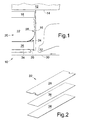
- the printhead assembly includes a resonator 12 having an orifice plate 14 for generating filaments of ink 16.
- the resonator stimulates the filaments to break off into droplets in the region of a charge plate 18 associated with a catcher assembly, generally designated 20.
- the catcher assembly 20 comprises a catcher 22, a catcher throat 24, and a catcher plate 26. Drops of ink are selectively charged by charging electrodes and deflected onto catcher face 28 and into catcher throat 24. Uncharged drops proceed undeflected to a print medium 30. Collected ink is withdrawn and recirculated.
- the wicking device 32 of the present invention comprises a porous polymer 34 for collecting ink mist, ink splatter and condensation from a surface of the printhead, with the exemplary surface shown here being a catcher plate.
- the wicking device 32 also comprises a differential adhesive layer 36, between the surface (i.e., the catcher plate) and the porous polymer 34.
- the differential adhesive layer 36 has a first or top side for contacting the moisture sensitive surface, such as catcher plate 26, and a second or bottom side for contacting the porous polymer 34.
- the side of the adhesive layer contacting the moisture sensitive surface will have lower adhesion properties than the side of the adhesive layer contacting the porous polymer 34.
- the purpose of the present invention is to provide a device 32 for collecting ink splatter and condensation from a moisture sensitive surface, such as the bottom of the ink jet printhead 10.
- the device 32 is a low profile wicking device, which offers the advantage in the ink jet printing industry of decreasing the throw distance of the drops which can significantly improve print quality.
- the light weight of the device 32 also allows the wicking pad to be attached to moveable components of the printhead, such as the eyelid, without affecting the actuator.
- the device 32 comprises a laminated structure that utilizes differential adhesive to achieve high adhesion to a wicking material and low adhesion to the catcher or other printhead component such as an eyelid, where removal is desired.
- a 4-to-1 or greater differential is desirable. If the removal adhesion from the printhead component is greater than 5 oz/in, removal of the wicking pad from the catcher plate or other printhead component can damage the catcher plate bond or otherwise damage the printhead component.
- the differential adhesive must have a adhesion of greater than 20 oz/in on the side attached to the porous polymer layer. Lower levels of adhesion to the porous polymer material can lead to delamination of this bond.
- the differential adhesive layer 36 is applied to the moisture sensitive surface, such as the catcher plate 26, on a mounting side of the moisture sensitive surface.
- the moisture sensitive surface such as the catcher plate 26
- differential adhesives are commercially available, prior use of such materials in ink jet is unknown.
- the side of the adhesive layer that contacts the catcher plate has low adhesion properties, to promote removal of the ink splatter and condensation.
- the side of the adhesion layer opposite the catcher plate contacts the porous polymer layer 34.
- the porous polymer is preferably a hydrophilic, high density, polyethylene filter material, as a hydrophilic material promotes wicking.
- the high density, polyethylene filter is compatible with our inks. Unlike cellulose based materials, this material does not swell when it gets wet. Materials that swell would require increased clearance between the print medium and the printhead to allow for the swelling.
- the filter material is an open cell structure with a high void fraction for collecting the ink. Suitable porous polymers are commercially available.
- the wicking nature of the material disperses the ink throughout the porous material. This increases the surface area of the ink so that moisture can be evaporating from some portions of the wicking pad while additional moisture is accumulating in other areas. As a result, the effective holding capacity for ink mist can be quite large.
- the low adhesion to the catcher plate, or other printhead components, provided by the differential adhesive, allows the wicking pad to be easily removed.
- the preferred polyethylene filter material provides sufficient strength to the wicking pad so that it does not tear when it is peeled from the catcher plate or other printhead components.
- the low cost of this wicking pad eliminates the financial and burdensome requirement of reusing the pad. The spent pad can therefore be disposed of and a new wicking pad easily installed.
- a differential adhesion approach allows the effective print distance to be closer to the substrate, which is very desirable for the printing process. Since the differential adhesive is no thicker than 0.005", with 0.003" being a preferred thickness, the polymer device can achieve the desired low profile arrangement.
- Some existing wicking devices utilize a magnet, increasing the distance to the substrate by 0.06".
- some existing wicking devices use a fastener, which involves use of tools, and requires consideration of clearances for the head of the screw or other fastener. These techniques add greatly to the throw distance of the printhead.
- a thin absorption pad or porous polymer 34 is highly desirable so that minimum throw distance is achieved.
- the prior art uses a pad thickness of 0.06".
- the present invention makes use of a hydrophillic, high density polyethylene polymer filter material with a pore size of 30-150 micron, 80 microns being preferred, and a thickness of only about 0.005 to 0.050", with a thickness of 0.024" being preferred.
- the device of the present invention eliminates ink and condensation pooling so that drips do not form and fall onto the printing material.
- the device also helps to absorb the ink mist/splatter generated when ink drops hit the substrate.
Landscapes
- Ink Jet (AREA)
Applications Claiming Priority (2)
| Application Number | Priority Date | Filing Date | Title |
|---|---|---|---|
| US916992 | 2001-07-27 | ||
| US09/916,992 US6527363B1 (en) | 2001-07-27 | 2001-07-27 | Low profile disposable polymer wicking pad |
Publications (3)
| Publication Number | Publication Date |
|---|---|
| EP1279504A2 true EP1279504A2 (de) | 2003-01-29 |
| EP1279504A3 EP1279504A3 (de) | 2003-09-10 |
| EP1279504B1 EP1279504B1 (de) | 2005-04-20 |
Family
ID=25438199
Family Applications (1)
| Application Number | Title | Priority Date | Filing Date |
|---|---|---|---|
| EP02255124A Expired - Lifetime EP1279504B1 (de) | 2001-07-27 | 2002-07-22 | Flachprofil-Wegwerfpolymerkapillarkissen |
Country Status (3)
| Country | Link |
|---|---|
| US (1) | US6527363B1 (de) |
| EP (1) | EP1279504B1 (de) |
| DE (1) | DE60203764T2 (de) |
Cited By (1)
| Publication number | Priority date | Publication date | Assignee | Title |
|---|---|---|---|---|
| WO2013090022A1 (en) * | 2011-12-15 | 2013-06-20 | Eastman Kodak Company | Reducing condensation accumulation in printing systems |
Families Citing this family (7)
| Publication number | Priority date | Publication date | Assignee | Title |
|---|---|---|---|---|
| US6592213B2 (en) * | 2001-12-14 | 2003-07-15 | Eastman Kodak Company | Continuous ink jet catcher |
| US6648461B2 (en) * | 2001-12-14 | 2003-11-18 | Eastman Kodak Company | Continuous ink jet catcher |
| US6736498B2 (en) * | 2002-09-25 | 2004-05-18 | Eastman Kodak Company | Eyelid positioning |
| US6688733B1 (en) * | 2002-09-25 | 2004-02-10 | Scitex Digital Printing, Inc. | Rapid pressure ramp startup |
| US7144102B2 (en) * | 2004-05-05 | 2006-12-05 | Eastman Kodak Company | Supression of Marangoni Effect on the catcher face |
| US9481777B2 (en) | 2012-03-30 | 2016-11-01 | The Procter & Gamble Company | Method of dewatering in a continuous high internal phase emulsion foam forming process |
| US8534794B1 (en) | 2012-10-11 | 2013-09-17 | Xerox Corporation | Ink recirculation system having a porous pad |
Family Cites Families (11)
| Publication number | Priority date | Publication date | Assignee | Title |
|---|---|---|---|---|
| US4268836A (en) * | 1979-10-25 | 1981-05-19 | The Mead Corporation | Ink jet printer having improved catcher |
| JPS5784858A (en) * | 1980-11-18 | 1982-05-27 | Ricoh Co Ltd | Ink mist recovery device |
| US4554193A (en) * | 1984-05-21 | 1985-11-19 | Ende Company | Substrate with differential adhesion |
| JPS6260655A (ja) * | 1985-09-11 | 1987-03-17 | Toshiba Corp | インクジエツト式記録装置 |
| JPH04214358A (ja) * | 1990-12-10 | 1992-08-05 | Canon Inc | インクジェット記録手段および該記録手段を用いるインクジェット記録装置 |
| WO1993008026A1 (en) * | 1991-10-15 | 1993-04-29 | Eastman Kodak Company | Contamination control construction for continuous ink jet print head |
| JPH08295858A (ja) * | 1995-04-26 | 1996-11-12 | Atsushi Inonami | 強さの異なる糊面を注意書きで表示してある強弱両面テープ |
| DE69606217T2 (de) * | 1995-05-04 | 2000-09-07 | Scitex Digital Printing, Inc. | Tintennebelsammler mit porösem Boden |
| US6331335B1 (en) * | 1995-07-10 | 2001-12-18 | Argent Automotive Systems, Inc. | Self-adhesive wire strap and methods of constructing and utilizing same |
| US5827589A (en) * | 1995-07-10 | 1998-10-27 | Autterson; Christopher S. | Strap devices, and methods of constructing and utilizing same |
| US6296344B1 (en) * | 1999-12-22 | 2001-10-02 | Eastman Kodak Company | Method for replenishing coatings on printhead nozzle plate |
-
2001
- 2001-07-27 US US09/916,992 patent/US6527363B1/en not_active Expired - Lifetime
-
2002
- 2002-07-22 EP EP02255124A patent/EP1279504B1/de not_active Expired - Lifetime
- 2002-07-22 DE DE60203764T patent/DE60203764T2/de not_active Expired - Lifetime
Cited By (1)
| Publication number | Priority date | Publication date | Assignee | Title |
|---|---|---|---|---|
| WO2013090022A1 (en) * | 2011-12-15 | 2013-06-20 | Eastman Kodak Company | Reducing condensation accumulation in printing systems |
Also Published As
| Publication number | Publication date |
|---|---|
| US6527363B1 (en) | 2003-03-04 |
| EP1279504A3 (de) | 2003-09-10 |
| DE60203764T2 (de) | 2006-03-02 |
| DE60203764D1 (de) | 2005-05-25 |
| EP1279504B1 (de) | 2005-04-20 |
Similar Documents
| Publication | Publication Date | Title |
|---|---|---|
| US6527363B1 (en) | Low profile disposable polymer wicking pad | |
| US6188416B1 (en) | Orifice array for high density ink jet printhead | |
| EP0561205B1 (de) | Auffangvorrichtung für kontinuierlichen Tintenstrahl mit Schirmstruktur | |
| JP4251861B2 (ja) | 連続式インクキャッチャーを含むインクジェットプリンタ | |
| JP4251862B2 (ja) | 連続式インクキャッチャーを含むインクジェットプリンタ | |
| US6820970B2 (en) | Continuous ink jet catcher having delimiting edge and ink accumulation border | |
| JPS618357A (ja) | ドツトプリンタ | |
| JP2000043243A (ja) | インクジェット記録装置 | |
| US7144103B2 (en) | Beveled charge structure | |
| EP0741040B1 (de) | Tintennebelsammler mit porösem Boden | |
| US5980027A (en) | Ink jet print head including adhesive layers enabling optimal electrode coverage and ink droplet velocity | |
| EP1308291B1 (de) | Tintenauffangvorrichtung mit abgrenzender Kante für kontinuierlichen Tintenstrahldrucker | |
| EP0882591B1 (de) | Elektrostatischer Tintenstrahldruckkopf mit einem mit konkaven und konvexen Teilen versehenen Kopfchip | |
| JP4200366B2 (ja) | インクジェット記録装置 | |
| JPS60151060A (ja) | インクジエツト記録装置 | |
| WO1993008026A1 (en) | Contamination control construction for continuous ink jet print head | |
| JPH04163050A (ja) | インクジェットヘッド | |
| JPH04235050A (ja) | インクジェット記録ヘッドの製造方法 | |
| JPS58185270A (ja) | インク噴射記録装置 | |
| JPS58212954A (ja) | インクジエツト記録装置 | |
| JPS60196360A (ja) | インクジエツトヘツドの励振方法 | |
| JPH0229342A (ja) | インクジェット記録装置 | |
| JPS61244558A (ja) | インクジエツト記録方法 | |
| JPS5973954A (ja) | インクジエツト記録装置 |
Legal Events
| Date | Code | Title | Description |
|---|---|---|---|
| PUAI | Public reference made under article 153(3) epc to a published international application that has entered the european phase |
Free format text: ORIGINAL CODE: 0009012 |
|
| AK | Designated contracting states |
Designated state(s): AT BE BG CH CY CZ DE DK EE ES FI FR GB GR IE IT LI LU MC NL PT SE SK TR |
|
| AX | Request for extension of the european patent |
Extension state: AL LT LV MK RO SI |
|
| PUAL | Search report despatched |
Free format text: ORIGINAL CODE: 0009013 |
|
| 17P | Request for examination filed |
Effective date: 20030613 |
|
| AK | Designated contracting states |
Kind code of ref document: A3 Designated state(s): AT BE BG CH CY CZ DE DK EE ES FI FR GB GR IE IT LI LU MC NL PT SE SK TR |
|
| AX | Request for extension of the european patent |
Extension state: AL LT LV MK RO SI |
|
| RIC1 | Information provided on ipc code assigned before grant |
Ipc: 7B 41J 2/09 A Ipc: 7B 41J 2/16 B Ipc: 7B 41J 2/20 B |
|
| 17Q | First examination report despatched |
Effective date: 20040319 |
|
| AKX | Designation fees paid |
Designated state(s): DE FR GB |
|
| RAP1 | Party data changed (applicant data changed or rights of an application transferred) |
Owner name: EASTMAN KODAK COMPANY |
|
| GRAP | Despatch of communication of intention to grant a patent |
Free format text: ORIGINAL CODE: EPIDOSNIGR1 |
|
| GRAS | Grant fee paid |
Free format text: ORIGINAL CODE: EPIDOSNIGR3 |
|
| GRAA | (expected) grant |
Free format text: ORIGINAL CODE: 0009210 |
|
| AK | Designated contracting states |
Kind code of ref document: B1 Designated state(s): DE FR GB |
|
| REG | Reference to a national code |
Ref country code: GB Ref legal event code: FG4D |
|
| REG | Reference to a national code |
Ref country code: IE Ref legal event code: FG4D |
|
| REF | Corresponds to: |
Ref document number: 60203764 Country of ref document: DE Date of ref document: 20050525 Kind code of ref document: P |
|
| PLBE | No opposition filed within time limit |
Free format text: ORIGINAL CODE: 0009261 |
|
| STAA | Information on the status of an ep patent application or granted ep patent |
Free format text: STATUS: NO OPPOSITION FILED WITHIN TIME LIMIT |
|
| ET | Fr: translation filed | ||
| 26N | No opposition filed |
Effective date: 20060123 |
|
| PGFP | Annual fee paid to national office [announced via postgrant information from national office to epo] |
Ref country code: FR Payment date: 20120712 Year of fee payment: 11 |
|
| PGFP | Annual fee paid to national office [announced via postgrant information from national office to epo] |
Ref country code: GB Payment date: 20130624 Year of fee payment: 12 |
|
| REG | Reference to a national code |
Ref country code: FR Ref legal event code: ST Effective date: 20140331 |
|
| PG25 | Lapsed in a contracting state [announced via postgrant information from national office to epo] |
Ref country code: FR Free format text: LAPSE BECAUSE OF NON-PAYMENT OF DUE FEES Effective date: 20130731 |
|
| GBPC | Gb: european patent ceased through non-payment of renewal fee |
Effective date: 20140722 |
|
| PG25 | Lapsed in a contracting state [announced via postgrant information from national office to epo] |
Ref country code: GB Free format text: LAPSE BECAUSE OF NON-PAYMENT OF DUE FEES Effective date: 20140722 |
|
| PGFP | Annual fee paid to national office [announced via postgrant information from national office to epo] |
Ref country code: DE Payment date: 20150731 Year of fee payment: 14 |
|
| REG | Reference to a national code |
Ref country code: DE Ref legal event code: R119 Ref document number: 60203764 Country of ref document: DE |
|
| PG25 | Lapsed in a contracting state [announced via postgrant information from national office to epo] |
Ref country code: DE Free format text: LAPSE BECAUSE OF NON-PAYMENT OF DUE FEES Effective date: 20170201 |