EP1279346A1 - Method of controlling a device for machining forms, in particular shoemaking models, and device for machining forms, in particular shoemaking models - Google Patents
Method of controlling a device for machining forms, in particular shoemaking models, and device for machining forms, in particular shoemaking models Download PDFInfo
- Publication number
- EP1279346A1 EP1279346A1 EP02016745A EP02016745A EP1279346A1 EP 1279346 A1 EP1279346 A1 EP 1279346A1 EP 02016745 A EP02016745 A EP 02016745A EP 02016745 A EP02016745 A EP 02016745A EP 1279346 A1 EP1279346 A1 EP 1279346A1
- Authority
- EP
- European Patent Office
- Prior art keywords
- machining
- rotation axis
- rotating
- reference surface
- shoemaking
- Prior art date
- Legal status (The legal status is an assumption and is not a legal conclusion. Google has not performed a legal analysis and makes no representation as to the accuracy of the status listed.)
- Withdrawn
Links
Images

Classifications
-
- A—HUMAN NECESSITIES
- A43—FOOTWEAR
- A43D—MACHINES, TOOLS, EQUIPMENT OR METHODS FOR MANUFACTURING OR REPAIRING FOOTWEAR
- A43D3/00—Lasts
- A43D3/02—Lasts for making or repairing shoes
-
- A—HUMAN NECESSITIES
- A43—FOOTWEAR
- A43D—MACHINES, TOOLS, EQUIPMENT OR METHODS FOR MANUFACTURING OR REPAIRING FOOTWEAR
- A43D1/00—Foot or last measuring devices; Measuring devices for shoe parts
-
- B—PERFORMING OPERATIONS; TRANSPORTING
- B27—WORKING OR PRESERVING WOOD OR SIMILAR MATERIAL; NAILING OR STAPLING MACHINES IN GENERAL
- B27M—WORKING OF WOOD NOT PROVIDED FOR IN SUBCLASSES B27B - B27L; MANUFACTURE OF SPECIFIC WOODEN ARTICLES
- B27M3/00—Manufacture or reconditioning of specific semi-finished or finished articles
- B27M3/20—Manufacture or reconditioning of specific semi-finished or finished articles of lasts; of shoes, e.g. sabots; of parts of shoes, e.g. heels
Definitions
- the present invention relates to a method of controlling a device for machining forms, in particular shoemaking models, and to a device for machining forms, in particular shoemaking models.
- Devices for machining forms, in particular shoemaking models which comprise a spindle for rotating a form about an axis of rotation, and a cutting tool movable to and from the form to remove material from and shape the form to obtain a form defining a shoemaking model.
- Known machining devices are supplied with input data which forms a mathematical model describing a three-dimensional reference surface of a reference model, and is used to automatically control rotation of the form and tool to produce on the form a surface conforming with the reference surface of the model.
- Known devices require two end supporting bodies (salvage) which are inserted in opposite portions of the form, extend axially close to a toe portion and a heel portion of the form, and are connected to the mechanical members (spindle and tailstock) by which the form is rotated.
- the supporting bodies are later removed manually by a skilled worker who cuts the supporting body without affecting the automatically machined surface; and the cutting area must form a surface blending with the machined surface.
- the present invention also relates to a device for machining forms, in particular shoemaking models, as claimed in Claim 13.
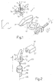
- Number 1 in Figure 1 indicates as a whole a device for machining forms, in particular shoemaking models.
- Device 1 comprises a machining tool 3 rotating about an axis 4 and in turn comprising, in the example shown, a rod 5 rotated about axis 4 by drive means (not shown), and three cutting tools 7 (e.g. in the form of cups with peripheral cutting edges) located on the ends of respective arms 9 extending radially from one end of rod 5. Rotation of rod 5 rotates cutting tools 7 to form a toroidal machining area 10. More specifically, cups 7 are coaxial with axes AB perpendicular to axis of rotation 4, and have annular cutting edges 7b lying in planes parallel to axis of rotation 4.
- Machining tool 3 is carried by a robot device (not shown) and moves in a three-dimensional space in three perpendicular directions X, Y and Z.
- Device 1 also comprises a supporting and positioning device 14 (shown schematically) for supporting a form F for machining, and for rotating form F about a first axis of rotation A and about a second axis of rotation B perpendicular to first axis of rotation A.
- a supporting and positioning device 14 shown schematically for supporting a form F for machining, and for rotating form F about a first axis of rotation A and about a second axis of rotation B perpendicular to first axis of rotation A.
- Supporting and orienting device 14 comprises an elongated (e.g. L-shaped) portion 15 which rotates about axis A and terminates with an end portion 15a to which is fixed a portion of form F corresponding to the edge portion of the foot-insertion opening of the respective shoe.
- elongated (e.g. L-shaped) portion 15 which rotates about axis A and terminates with an end portion 15a to which is fixed a portion of form F corresponding to the edge portion of the foot-insertion opening of the respective shoe.
- Form F is roughly parallelepiped-shaped and made of material (e.g. plastic or wood) which can be machined easily by tool 3 to obtain a finished shoemaking model at the end of a machining cycle described later on.
- material e.g. plastic or wood
- the finished shoemaking model is used in known manner to support and shape leather into a vamp.
- machining tool 3 is operated on the basis of a memorized mathematical reference model to obtain a shoemaking model defined by an outer surface conforming with the arrangement of points of a reference surface defined by the mathematical model.
- the mathematical model is determined using a device 20 for determining forms, in particular shoemaking models 22, which may be made manually by a model-maker, e.g. from wood or plastic.
- device 20 ( Figure 2) comprises a rotating device 26 for supporting and rotating model 22 about a vertical axis 30. More specifically, rotating device 26 comprises a cylindrical base 32; and a shaft 33 coaxial with axis 30 and rotated by an electric motor (not shown) with respect to cylindrical base 32.
- shaft 33 fits inside a coaxial hole (not shown) in model 22, which is fixed firmly to shaft 33 and rotated about axis 30.
- a known viewing device 35 determines three-dimensional coordinates P(z,c,p) of points Pi on the surface S of model 22.
- Three-dimensional coordinates P(z,c,p) are expressed with respect to a number of machine references, wherein axis Z is a vertical axis parallel to axis 30, quantity c is an angle value indicating the angle of rotation about axis 30 with respect to a vertical reference plane PR , and coordinate p indicates a determined depth.
- Device 35 preferably comprises a viewing device 37 - in particular a television camera - movable reversibly along axis Z to and from model 22.
- model 22 is rotated about axis 30 when locating points Pi so as to determine, for a given value along axis Z, the three-dimensional coordinates P(z,c,p) of a number of points P1, P2, ... Pi ... Pmax located along a parallel profile Pp of model 22 and lying in a plane Kp perpendicular to axis 30.
- Device 35 locates points Pi for different values along axis Z , so as to scan model 22 in a number of parallel planes Kp. More specifically, adjacent planes Kp i and Kp i+1 are separated along axis 30 by a generally constant spacing z .
- the set W of all the points located in the various planes defines the mathematical reference model describing the outline in space of reference surface S of model 22, which is therefore used as a reference.
- the located point set is used in the method according to the present invention to control device 1 and shape a form having an outer surface conforming with - e.g. identical with or related by a scale factor to - the reference surface.
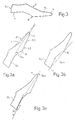
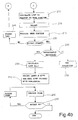
- processing of set W comprises a first block 100 ( Figure 4a) which, by means of known mathematical procedures, extracts the two-dimensional information relative to the longitudinal section SL ( Figure 3) of the shoemaking model.
- Longitudinal section SL is defined by a number of connected portions, and comprises a front toe portion P; a front arch portion B corresponding to the portion of the shoe supporting the articulation of the foot; a heel portion T corresponding to the portion of the shoe to which the heel is applied; an instep portion C; and a rear portion TL corresponding to the rear portion of model 22.
- Block 100 is followed by a block 110 which, for the longitudinal section of toe portion P, calculates a first and second line R1, R2 ( Figure 3a) approximating (a known approximation method, such as the least squares method, may be used) sides L1, L2 defining toe portion P.
- the section of toe portion P in fact has a typical triangular outline, two adjacent sides L1, L2 of which may be approximated by lines R1 and R2.
- Block 110 is followed by a block 120 which calculates the bisector Rb of the acute angle between lines R1 and R2.
- Bisector Rb corresponds to the bisector of toe portion P.
- Block 120 is followed by a block 130 which orients the work form by rotating it about first axis of rotation A. More specifically, the form is rotated to shape a toe portion in which the bisector of the longitudinal section is aligned (i.e. parallel) with the vertical.
- Block 130 is followed by a block 140 which commands machining of toe portion P of the work form. More specifically, machining tool 3 moves about the portion of the work form corresponding to toe P, and removes material to form a surface reproducing the reference surface described by point set W and having the bisector physically aligned with the vertical.
- Block 140 is followed by a block 150 which commands machining of front arch portion B of the work form. More specifically, machining tool 3 moves about the portion of the work form corresponding to front arch B, and removes material to form a surface reproducing the reference surface described by point set W.
- Block 150 is followed by a block 160 which calculates, on longitudinal section SL, the line R b-t ( Figure 3b) joining front arch portion B to heel portion T.
- Block 160 is followed by a block 170 which orients the work form (rotates it about axis A) to shape a form in which line R b-t is aligned with the vertical.
- Block 170 is followed by a block 180 which commands machining of the arch portion (shank) extending between the front arch and heel portions of the work form. More specifically, machining tool 3 moves about the arch portion of the work form, and removes material to form a surface reproducing the corresponding reference surface described by point set W and having line R b-t physically aligned with the horizontal.
- machining tool 3 moves about the arch portion of the work form, and removes material to form a surface reproducing the corresponding reference surface described by point set W and having line R b-t physically aligned with the horizontal.
- Block 180 is followed by a block 185 which adjusts the position of the work form (rotates it clockwise/anticlockwise about axis A) to machine the instep portion of the form while preventing rod 5 of machining tool 3 from contacting the toe portion of the work form.
- Block 185 is followed by a block 190 which commands machining of instep portion C of the work form. More specifically, machining tool 3 moves about the portion of the work form corresponding to instep C, and removes material to form a surface reproducing the corresponding reference surface described by point set W.
- Block 190 is followed by a block 200 (Figure 4b) which calculates, on longitudinal section SL, the line R t tangent to heel portion T ( Figure 3c).
- Block 200 is followed by a block 205 which orients the work form (rotates it about axis A) to shape a form in which line R t is perpendicular to the vertical.
- Block 205 is followed by a block 210 which machines rear portion TL of the work form. More specifically, machining tool 3 moves about the portion of the work form corresponding to heel TL, and removes material to form a surface reproducing the corresponding reference surface described by point set W.
- Block 210 is followed by a block 220, which determines whether the above machining cycles are to be repeated. If they are not (end of cycles), block 220 is followed by a block 230; conversely (cycles to be repeated), block 220 is followed by a block 240 in which the system waits for machining tool 3 to be changed. Once the tool is changed, block 240 goes back to block 110 to repeat machining of the form using a different tool 3, in particular with smaller cutting tools 7 for greater precision machining.
- Repetition of the machining cycles may comprise repetition of a smaller number of blocks to repeat only some of the machining operations; and the order in which the machining operations are performed (the first time and subsequent repetitions) may be other than as shown.
- Block 230 determines whether a further machining cycle is required to obtain an orthopaedic form 2. If it is not, block 230 is followed by an end block 250; conversely (orthopaedic machining required), block 230 is followed by an orthopaedic cycle start block 260.
- block 260 calculates, on longitudinal section SL, the line Rp-t ( Figure 3c) joining toe P to heel T of section SL.
- Block 260 is followed by a block 270 which orients the work form by rotating it about second axis of rotation B. More specifically, the form is rotated to shape a form having a longitudinal section in which toe-heel line Rp-t is aligned with (i.e. parallel to) the horizontal.
- Block 270 is followed by a block 280 which commands engraving of a portion of the form. This is done using a tool (burin) for forming underside cavities in the form, and which may be controlled on the basis of memorized data other than data set W.
- a tool burin
- Block 280 is followed by a block 290 which determines whether the form is to be rotated 90° about axis B. If it is, the form is rotated and block 280 is again selected to machine another portion of the form; conversely, the cycle is terminated. Repetition of blocks 280 and 290 provides for machining different portions of the form, such as a portion corresponding to the toe, a portion corresponding to the right side, a portion corresponding to the sole, and a portion corresponding to the left side.
- the only portion which is not machined completely is the contact portion between the form and end 15a, which, corresponding on the shoe to the edge portion of the foot-insertion opening, is not particularly critical technically and, if necessary, can easily be worked manually later.
- the particular toroidal geometry provides for easily shaping the outer surfaces of the form, which, as is known, vary considerably in slope with respect to rotation axis. Shaping as described with reference to Figures 4a, 4b provides for machining all parts of the form (toe, front arch, heel, instep, rear) to obtain surfaces conforming perfectly with the reference surfaces of the mathematical model.
Abstract
A method of controlling a device for machining forms, in particular shoemaking models, and including the steps of: providing a machining tool (3) rotated about an axis of rotation (4) and forming, when in motion, a toroidal machining area (10); moving the machining tool (3) in a three-dimensional space in three perpendicular directions; supporting and orienting (14) a work form (F) by rotating the form (F) about at least a first form rotation axis (A); acquiring a set of data (W) defining a reference surface for the form, and processing (100-290) the data to control operation of the machining tool (3) to remove material from the form and obtain on the form a surface conforming with the reference surface.
Description
- The present invention relates to a method of controlling a device for machining forms, in particular shoemaking models, and to a device for machining forms, in particular shoemaking models.
- Devices for machining forms, in particular shoemaking models, are known which comprise a spindle for rotating a form about an axis of rotation, and a cutting tool movable to and from the form to remove material from and shape the form to obtain a form defining a shoemaking model.
- Leather is placed on and adheres to the surfaces of the model, and is then shaped to form a vamp.
- Known machining devices are supplied with input data which forms a mathematical model describing a three-dimensional reference surface of a reference model, and is used to automatically control rotation of the form and tool to produce on the form a surface conforming with the reference surface of the model.
- Known devices require two end supporting bodies (salvage) which are inserted in opposite portions of the form, extend axially close to a toe portion and a heel portion of the form, and are connected to the mechanical members (spindle and tailstock) by which the form is rotated.
- The supporting bodies are later removed manually by a skilled worker who cuts the supporting body without affecting the automatically machined surface; and the cutting area must form a surface blending with the machined surface.
- The manual work involved obviously calls for skill and, if not performed properly, may seriously impair the automatically machined form.
- It is an object of the present invention to provide a method designed to eliminate the drawbacks of known methods, and which at the same time provides for effectively controlling the form machining device to ensure a good machining standard of each part of the form.
- According to the present invention, there is provided a method of controlling a device for machining forms, in particular shoemaking models, as claimed in Claim 1.
- The present invention also relates to a device for machining forms, in particular shoemaking models, as claimed in Claim 13.
- A non-limiting embodiment of the invention will be described by way of example with reference to the accompanying drawings, in which:
- Figure 1 shows a schematic view in perspective of a device for machining forms, in particular shoemaking models, and implementing the method according to the present invention;
- Figure 2 shows a schematic view in perspective of a device for determining forms, in particular shoemaking models, and for acquiring data used in the method according to the present invention;
- Figures 3, 3a, 3b and 3c show geometric diagrams of operations performed by the device and method according to the present invention;
- Figures 4a, 4b show flow charts of operations performed in the method according to the invention.
- Number 1 in Figure 1 indicates as a whole a device for machining forms, in particular shoemaking models.
- Device 1 comprises a machining tool 3 rotating about an
axis 4 and in turn comprising, in the example shown, a rod 5 rotated aboutaxis 4 by drive means (not shown), and three cutting tools 7 (e.g. in the form of cups with peripheral cutting edges) located on the ends ofrespective arms 9 extending radially from one end of rod 5. Rotation of rod 5 rotates cutting tools 7 to form a toroidal machining area 10. More specifically, cups 7 are coaxial with axes AB perpendicular to axis ofrotation 4, and haveannular cutting edges 7b lying in planes parallel to axis ofrotation 4. - Machining tool 3 is carried by a robot device (not shown) and moves in a three-dimensional space in three perpendicular directions X, Y and Z.
- Device 1 also comprises a supporting and positioning device 14 (shown schematically) for supporting a form F for machining, and for rotating form F about a first axis of rotation A and about a second axis of rotation B perpendicular to first axis of rotation A.
- Supporting and
orienting device 14 comprises an elongated (e.g. L-shaped)portion 15 which rotates about axis A and terminates with anend portion 15a to which is fixed a portion of form F corresponding to the edge portion of the foot-insertion opening of the respective shoe. - Form F is roughly parallelepiped-shaped and made of material (e.g. plastic or wood) which can be machined easily by tool 3 to obtain a finished shoemaking model at the end of a machining cycle described later on.
- The finished shoemaking model is used in known manner to support and shape leather into a vamp.
- More specifically, machining tool 3 is operated on the basis of a memorized mathematical reference model to obtain a shoemaking model defined by an outer surface conforming with the arrangement of points of a reference surface defined by the mathematical model.
- For a clear understanding of how the cutting tool is operated, the following is a brief description of the way in which the mathematical reference model points describing the outer surface of the model are located.
- The mathematical model is determined using a
device 20 for determining forms, inparticular shoemaking models 22, which may be made manually by a model-maker, e.g. from wood or plastic. - In the embodiment shown, device 20 (Figure 2) comprises a
rotating device 26 for supporting and rotatingmodel 22 about avertical axis 30. More specifically,rotating device 26 comprises acylindrical base 32; and ashaft 33 coaxial withaxis 30 and rotated by an electric motor (not shown) with respect tocylindrical base 32. - More specifically, the top end of
shaft 33 fits inside a coaxial hole (not shown) inmodel 22, which is fixed firmly toshaft 33 and rotated aboutaxis 30. - A known
viewing device 35 determines three-dimensional coordinates P(z,c,p) of points Pi on the surface S ofmodel 22. - Three-dimensional coordinates P(z,c,p) are expressed with respect to a number of machine references, wherein axis Z is a vertical axis parallel to
axis 30, quantity c is an angle value indicating the angle of rotation aboutaxis 30 with respect to a vertical reference plane PR, and coordinate p indicates a determined depth. -
Device 35 preferably comprises a viewing device 37 - in particular a television camera - movable reversibly along axis Z to and frommodel 22. - More specifically,
model 22 is rotated aboutaxis 30 when locating points Pi so as to determine, for a given value along axis Z, the three-dimensional coordinates P(z,c,p) of a number of points P1, P2, ... Pi ... Pmax located along a parallel profile Pp ofmodel 22 and lying in a plane Kp perpendicular toaxis 30.Device 35 locates points Pi for different values along axis Z, so as to scanmodel 22 in a number of parallel planes Kp. More specifically, adjacent planes Kp i and Kp i+1 are separated alongaxis 30 by a generally constant spacing z. - The set W of all the points located in the various planes defines the mathematical reference model describing the outline in space of reference surface S of
model 22, which is therefore used as a reference. - The located point set is used in the method according to the present invention to control device 1 and shape a form having an outer surface conforming with - e.g. identical with or related by a scale factor to - the reference surface.
- More specifically, processing of set W comprises a first block 100 (Figure 4a) which, by means of known mathematical procedures, extracts the two-dimensional information relative to the longitudinal section SL (Figure 3) of the shoemaking model.
- Longitudinal section SL is defined by a number of connected portions, and comprises a front toe portion P; a front arch portion B corresponding to the portion of the shoe supporting the articulation of the foot; a heel portion T corresponding to the portion of the shoe to which the heel is applied; an instep portion C; and a rear portion TL corresponding to the rear portion of
model 22. -
Block 100 is followed by ablock 110 which, for the longitudinal section of toe portion P, calculates a first and second line R1, R2 (Figure 3a) approximating (a known approximation method, such as the least squares method, may be used) sides L1, L2 defining toe portion P. The section of toe portion P in fact has a typical triangular outline, two adjacent sides L1, L2 of which may be approximated by lines R1 and R2. -
Block 110 is followed by ablock 120 which calculates the bisector Rb of the acute angle between lines R1 and R2. Bisector Rb corresponds to the bisector of toe portion P. -
Block 120 is followed by ablock 130 which orients the work form by rotating it about first axis of rotation A. More specifically, the form is rotated to shape a toe portion in which the bisector of the longitudinal section is aligned (i.e. parallel) with the vertical. -
Block 130 is followed by ablock 140 which commands machining of toe portion P of the work form. More specifically, machining tool 3 moves about the portion of the work form corresponding to toe P, and removes material to form a surface reproducing the reference surface described by point set W and having the bisector physically aligned with the vertical. -
Block 140 is followed by ablock 150 which commands machining of front arch portion B of the work form. More specifically, machining tool 3 moves about the portion of the work form corresponding to front arch B, and removes material to form a surface reproducing the reference surface described by point set W. -
Block 150 is followed by ablock 160 which calculates, on longitudinal section SL, the line Rb-t (Figure 3b) joining front arch portion B to heel portion T. -
Block 160 is followed by ablock 170 which orients the work form (rotates it about axis A) to shape a form in which line Rb-t is aligned with the vertical. -
Block 170 is followed by ablock 180 which commands machining of the arch portion (shank) extending between the front arch and heel portions of the work form. More specifically, machining tool 3 moves about the arch portion of the work form, and removes material to form a surface reproducing the corresponding reference surface described by point set W and having line Rb-t physically aligned with the horizontal. -
Block 180 is followed by ablock 185 which adjusts the position of the work form (rotates it clockwise/anticlockwise about axis A) to machine the instep portion of the form while preventing rod 5 of machining tool 3 from contacting the toe portion of the work form. -
Block 185 is followed by ablock 190 which commands machining of instep portion C of the work form. More specifically, machining tool 3 moves about the portion of the work form corresponding to instep C, and removes material to form a surface reproducing the corresponding reference surface described by point set W. -
Block 190 is followed by a block 200 (Figure 4b) which calculates, on longitudinal section SL, the line Rt tangent to heel portion T (Figure 3c). -
Block 200 is followed by ablock 205 which orients the work form (rotates it about axis A) to shape a form in which line Rt is perpendicular to the vertical. -
Block 205 is followed by ablock 210 which machines rear portion TL of the work form. More specifically, machining tool 3 moves about the portion of the work form corresponding to heel TL, and removes material to form a surface reproducing the corresponding reference surface described by point set W. -
Block 210 is followed by ablock 220, which determines whether the above machining cycles are to be repeated. If they are not (end of cycles),block 220 is followed by ablock 230; conversely (cycles to be repeated),block 220 is followed by ablock 240 in which the system waits for machining tool 3 to be changed. Once the tool is changed,block 240 goes back toblock 110 to repeat machining of the form using a different tool 3, in particular with smaller cutting tools 7 for greater precision machining. - Repetition of the machining cycles may comprise repetition of a smaller number of blocks to repeat only some of the machining operations; and the order in which the machining operations are performed (the first time and subsequent repetitions) may be other than as shown.
-
Block 230 determines whether a further machining cycle is required to obtain an orthopaedic form 2. If it is not, block 230 is followed by anend block 250; conversely (orthopaedic machining required), block 230 is followed by an orthopaediccycle start block 260. - More specifically, block 260 calculates, on longitudinal section SL, the line Rp-t (Figure 3c) joining toe P to heel T of section SL.
-
Block 260 is followed by ablock 270 which orients the work form by rotating it about second axis of rotation B. More specifically, the form is rotated to shape a form having a longitudinal section in which toe-heel line Rp-t is aligned with (i.e. parallel to) the horizontal. -
Block 270 is followed by ablock 280 which commands engraving of a portion of the form. This is done using a tool (burin) for forming underside cavities in the form, and which may be controlled on the basis of memorized data other than data set W. -
Block 280 is followed by ablock 290 which determines whether the form is to be rotated 90° about axis B. If it is, the form is rotated and block 280 is again selected to machine another portion of the form; conversely, the cycle is terminated. Repetition ofblocks - The advantages of the method according to the present invention will be clear from the foregoing description. In particular, using tool 3 defining a toroidal cutting area 10 combined with rotation of the form about axis A provides for precision machining the whole outer surface of the form with no need for two end supporting bodies.
- The only portion which is not machined completely is the contact portion between the form and
end 15a, which, corresponding on the shoe to the edge portion of the foot-insertion opening, is not particularly critical technically and, if necessary, can easily be worked manually later. - The particular toroidal geometry provides for easily shaping the outer surfaces of the form, which, as is known, vary considerably in slope with respect to rotation axis. Shaping as described with reference to Figures 4a, 4b provides for machining all parts of the form (toe, front arch, heel, instep, rear) to obtain surfaces conforming perfectly with the reference surfaces of the mathematical model.
- Clearly changes may be made to the method of controlling a device for machining forms, in particular shoemaking models, and to the device for machining forms, in particular shoemaking models, as described and illustrated herein without, however, departing from the scope of the present invention.
Claims (14)
- A method of controlling a device for machining forms, in particular shoemaking models, characterized by comprising the steps of:- providing a machining tool (3) rotated by drive means about an axis of rotation (4) and forming, when in motion, a toroidal machining area (10);- moving said machining tool (3) in a three-dimensional space;- supporting and orienting (14) a work form (F) by rotating the form (F) about at least a first form rotation axis (A);- acquiring a set of data (W) defining a reference surface for said form, and processing (100-290) said data to control operation of said machining tool (3) to remove material from said form and obtain on the form a surface conforming with the reference surface.
- A method as claimed in Claim 1, and comprising the step of rotating said form (F) about a second form rotation axis (B) perpendicular to the first form rotation axis (A).
- A method as claimed in Claim 1 or 2, and comprising a step of processing said data to extract (100) two-dimensional information relative to the longitudinal section (SL) of a shoemaking model (22) reproduced from said reference surface;
said longitudinal section (SL) being defined by a number of connected portions, and comprising at least one of the following portions:a front toe portion (P);a front arch portion (B) corresponding to the portion of the shoe supporting the articulation of the foot;a heel portion (T) corresponding to the portion of the shoe to which the heel is applied;an instep portion (C);a rear portion (TL) corresponding to the rear portion of the model. - A method as claimed in Claim 3, and comprising a step of calculating (110) a first and a second line R1 R2 approximating the sides L1, L2 defining said toe portion (P);
said method also comprising the steps of:- calculating the bisector Rb of the acute angle between the first and second line R1, R2;- orienting (130) the work form by rotating said form about the first form rotation axis (A) to shape a toe portion of the form in which the bisector of the longitudinal section is aligned with the vertical;- machining (140) the toe portion (P) of the form by removing material to form a surface reproducing a respective surface described by the reference surface and having the bisector physically aligned with the vertical. - A method as claimed in Claim 3 or 4, and comprising a step of machining (150) the front arch portion (B) to form a surface reproducing a respective surface described by said reference surface.
- A method as claimed in Claim 3, 4 or 5, and comprising a calculating step (160) to determine, on said longitudinal section (SL), the line Rb-t joining the front arch portion (B) to the heel portion (T);
said method also comprising the steps of:- orienting (170) the work form by rotating said form about the first form rotation axis (A) to shape the form so that a corresponding line Rb-t is aligned with the vertical;- machining (180) the form at the arch portion extending between the front arch portion and the heel portion, by moving the machining tool to form a surface reproducing the corresponding surface described by the reference surface and having a line Rb-t physically aligned with the horizontal. - A method as claimed in any one of Claims 3 to 6, and comprising an adjusting step (185) by which the form is rotated about the first form rotation axis (A) to permit subsequent machining of the instep portion while preventing any contact between said machining tool (3) and the toe portion of the work form (F).
- A method as claimed in any one of Claims 3 to 7, and comprising a step (190) of machining the instep portion (C) of the form to produce a surface reproducing a respective surface described by said reference surface.
- A method as claimed in any one of Claims 3 to 8, and comprising a calculating step (200) to calculate, on said longitudinal section (SL), the line Rt tangent to the heel portion (T);
said method also comprising the steps of:- orienting (205) the work form by rotating said form about the first form rotation axis (A) to shape the form so that a corresponding line Rt is perpendicular to the vertical;- machining (210) the rear portion (TL) of the work form to produce a surface reproducing the corresponding surface described by the reference surface. - A method as claimed in any one of Claims 3 to 9, and comprising repetition of all or some of the previous machining operations.
- A method as claimed in any one of Claims 3 to 10 dependent on Claim 2, and comprising the step of calculating (260), on said longitudinal section (SL), the line Rp-t joining the toe portion (P) to the heel portion (T) of the longitudinal section (SL);
said method also comprising the steps of:- rotating said form about the second form rotation axis (B) so that the line Rp-t joining the toe portion to the heel portion of the form is aligned with the horizontal;- engraving (280) a portion of the form to produce at least one underside cavity in the form;- rotating said form about the second form rotation axis (B) to machine another portion of the form. - A method as claimed in any one of the foregoing Claims, characterized in that said step of supporting said form (F) comprises the step of fixing the portion of the form (F) corresponding, on the respective shoe, to the edge portion of the foot-insertion opening to one end of a body (15) rotating about said first form rotation axis (A).
- A device for machining forms, in particular shoemaking models, characterized by comprising:- a machining tool (3) rotated by drive means about an axis of rotation (4) and forming, when in motion, a toroidal machining area (10);- actuating means for moving said machining tool (3) in a three-dimensional space;- supporting and orienting means (14) for supporting and orienting a work form (F) and for rotating the form (F) about at least a first form rotation axis (A);- said device receiving a set of data (W) defining a reference surface for said work form; said data controlling said machining tool (3) to remove material from said form to obtain on the form a surface conforming with the reference surface.
- A device as claimed in Claim 13, wherein said supporting and orienting means (14) comprise an elongated portion (15) which rotates about said first form rotation axis (A) and terminates with an end portion (15a) to which is fixed a portion of the form (F) corresponding, on the respective shoe, to the edge portion of the foot-insertion opening.
Applications Claiming Priority (2)
| Application Number | Priority Date | Filing Date | Title |
|---|---|---|---|
| ITTO20010753 | 2001-07-27 | ||
| IT2001TO000753A ITTO20010753A1 (en) | 2001-07-27 | 2001-07-27 | METHOD FOR THE CONTROL OF A DEVICE FOR THE PROCESSING OF SHAPES, IN PARTICULAR FOOTWEAR MODELS AND DEVICE FOR THE PROCESSING |
Publications (1)
| Publication Number | Publication Date |
|---|---|
| EP1279346A1 true EP1279346A1 (en) | 2003-01-29 |
Family
ID=11459098
Family Applications (1)
| Application Number | Title | Priority Date | Filing Date |
|---|---|---|---|
| EP02016745A Withdrawn EP1279346A1 (en) | 2001-07-27 | 2002-07-26 | Method of controlling a device for machining forms, in particular shoemaking models, and device for machining forms, in particular shoemaking models |
Country Status (2)
| Country | Link |
|---|---|
| EP (1) | EP1279346A1 (en) |
| IT (1) | ITTO20010753A1 (en) |
Cited By (5)
| Publication number | Priority date | Publication date | Assignee | Title |
|---|---|---|---|---|
| EP2589311A1 (en) * | 2011-11-04 | 2013-05-08 | Spannrit Schuhkomponenten GmbH | Method and device for producing and adjusting customised orthopaedic shoe inserts |
| ITPI20120030A1 (en) * | 2012-03-23 | 2013-09-24 | Machinale S R L Fab | METHOD AND EQUIPMENT FOR THE IMPLEMENTATION OF SHAPES AND PLANTARS FOR FOOTWEAR |
| DE102020001470A1 (en) | 2020-03-06 | 2021-09-09 | Jan Legleitner | Device and method for the production of shoe lasts |
| DE102020004224A1 (en) | 2020-07-14 | 2022-01-20 | Jan Legleitner | Device and method for manufacturing shoe lasts |
| RU2805436C1 (en) * | 2023-05-25 | 2023-10-17 | Общество с ограниченной ответственностью ТАМИ и КО | Method for constructing shoe uppers |
Citations (5)
| Publication number | Priority date | Publication date | Assignee | Title |
|---|---|---|---|---|
| GB1375822A (en) * | 1970-06-30 | 1974-11-27 | ||
| EP0311925A2 (en) * | 1987-10-15 | 1989-04-19 | J.V. Footwear Technology, Inc. | Method and apparatus for making shoe lasts and/or shoe components |
| DE4310877A1 (en) * | 1993-04-02 | 1994-10-06 | Schaaf & Legleitner Gmbh | Numerically controlled machine for producing shoe lasts |
| DE19630426A1 (en) * | 1996-07-27 | 1998-01-29 | Schaaf & Legleitner Gmbh | CNC machining of shoemakers' last |
| EP0990399A2 (en) * | 1998-09-28 | 2000-04-05 | Newlast S.r.l. | Machine and method of producing accessories for the shoe industry |
-
2001
- 2001-07-27 IT IT2001TO000753A patent/ITTO20010753A1/en unknown
-
2002
- 2002-07-26 EP EP02016745A patent/EP1279346A1/en not_active Withdrawn
Patent Citations (5)
| Publication number | Priority date | Publication date | Assignee | Title |
|---|---|---|---|---|
| GB1375822A (en) * | 1970-06-30 | 1974-11-27 | ||
| EP0311925A2 (en) * | 1987-10-15 | 1989-04-19 | J.V. Footwear Technology, Inc. | Method and apparatus for making shoe lasts and/or shoe components |
| DE4310877A1 (en) * | 1993-04-02 | 1994-10-06 | Schaaf & Legleitner Gmbh | Numerically controlled machine for producing shoe lasts |
| DE19630426A1 (en) * | 1996-07-27 | 1998-01-29 | Schaaf & Legleitner Gmbh | CNC machining of shoemakers' last |
| EP0990399A2 (en) * | 1998-09-28 | 2000-04-05 | Newlast S.r.l. | Machine and method of producing accessories for the shoe industry |
Cited By (5)
| Publication number | Priority date | Publication date | Assignee | Title |
|---|---|---|---|---|
| EP2589311A1 (en) * | 2011-11-04 | 2013-05-08 | Spannrit Schuhkomponenten GmbH | Method and device for producing and adjusting customised orthopaedic shoe inserts |
| ITPI20120030A1 (en) * | 2012-03-23 | 2013-09-24 | Machinale S R L Fab | METHOD AND EQUIPMENT FOR THE IMPLEMENTATION OF SHAPES AND PLANTARS FOR FOOTWEAR |
| DE102020001470A1 (en) | 2020-03-06 | 2021-09-09 | Jan Legleitner | Device and method for the production of shoe lasts |
| DE102020004224A1 (en) | 2020-07-14 | 2022-01-20 | Jan Legleitner | Device and method for manufacturing shoe lasts |
| RU2805436C1 (en) * | 2023-05-25 | 2023-10-17 | Общество с ограниченной ответственностью ТАМИ и КО | Method for constructing shoe uppers |
Also Published As
| Publication number | Publication date |
|---|---|
| ITTO20010753A1 (en) | 2003-01-27 |
| ITTO20010753A0 (en) | 2001-07-27 |
Similar Documents
| Publication | Publication Date | Title |
|---|---|---|
| JPH01314502A (en) | Method and apparatus for inegrally molding sole to shoe main body | |
| US10624722B1 (en) | Systems and methods for laser trimming dental aligners | |
| EP3764832B1 (en) | Automated shoe assembly | |
| EP0041808B1 (en) | Determining an operating path of a tool in relation to a three-dimensional surface of a workpiece | |
| EP1652490A2 (en) | Production method of three-dimensional shape data of dental prosthesis | |
| JP2009129263A (en) | Method and program for machining press die, program for generating machining program, and machining device | |
| CN106163449A (en) | The processing method of prefabricated artificial tooth | |
| JPH05130905A (en) | Device for progressive operation along selected part of shoe instep | |
| JPH07236648A (en) | Artificial bone material and its processing method | |
| EP1279346A1 (en) | Method of controlling a device for machining forms, in particular shoemaking models, and device for machining forms, in particular shoemaking models | |
| EP0990399B1 (en) | Machine for producing accessories for the shoe industry | |
| EP3578070A1 (en) | Apparatus for the laser engraving of insoles and method for operating said apparatus | |
| KR20040074992A (en) | Last with grip device for shoemaking | |
| JP2004351199A (en) | Machining method of last for making shoe and numerically controlled machining center for the method | |
| US20020165637A1 (en) | Method for highly automated manufacture of metal parts | |
| EP0313312A2 (en) | Manufacture of lasts for footwear | |
| EP0919893A2 (en) | Processing machine with numerical control apparatus | |
| JP4464485B2 (en) | Processing method of dental prosthesis | |
| JPH02292121A (en) | Universal gear chamfering machine | |
| Denkena et al. | A concept for shoe last manufacturing in mass customisation | |
| TWI667970B (en) | Apparatus for processing a vamp and routing method thereof | |
| EP1044622A1 (en) | Automatic machine for finishing forms for shoe manufacturing starting from rough-shaped forms | |
| EP1424021B1 (en) | Device for positioning and clamping shaped elements and machine equipped with this device | |
| US20070161331A1 (en) | Stone fabrication positioning system | |
| JP2001269886A (en) | Method and device for accurately guiding machining tool provided with robot |
Legal Events
| Date | Code | Title | Description |
|---|---|---|---|
| PUAI | Public reference made under article 153(3) epc to a published international application that has entered the european phase |
Free format text: ORIGINAL CODE: 0009012 |
|
| AK | Designated contracting states |
Designated state(s): AT BE BG CH CY CZ DE DK EE ES FI FR GB GR IE IT LI LU MC NL PT SE SK TR |
|
| AX | Request for extension of the european patent |
Extension state: AL LT LV MK RO SI |
|
| 17P | Request for examination filed |
Effective date: 20030714 |
|
| AKX | Designation fees paid |
Designated state(s): AT BE BG CH CY CZ DE DK EE ES FI FR GB GR IE IT LI LU MC NL PT SE SK TR |
|
| 17Q | First examination report despatched |
Effective date: 20050307 |
|
| STAA | Information on the status of an ep patent application or granted ep patent |
Free format text: STATUS: THE APPLICATION IS DEEMED TO BE WITHDRAWN |
|
| 18D | Application deemed to be withdrawn |
Effective date: 20050719 |