EP1278620B1 - Verfahren und anlage zur herstellung von geschleuderten glasfaserverstärkten rohren - Google Patents
Verfahren und anlage zur herstellung von geschleuderten glasfaserverstärkten rohren Download PDFInfo
- Publication number
- EP1278620B1 EP1278620B1 EP01940371A EP01940371A EP1278620B1 EP 1278620 B1 EP1278620 B1 EP 1278620B1 EP 01940371 A EP01940371 A EP 01940371A EP 01940371 A EP01940371 A EP 01940371A EP 1278620 B1 EP1278620 B1 EP 1278620B1
- Authority
- EP
- European Patent Office
- Prior art keywords
- layers
- sand
- pipe
- glass fibre
- raw materials
- Prior art date
- Legal status (The legal status is an assumption and is not a legal conclusion. Google has not performed a legal analysis and makes no representation as to the accuracy of the status listed.)
- Expired - Lifetime
Links
- 239000003365 glass fiber Substances 0.000 title abstract description 19
- 238000000034 method Methods 0.000 title abstract description 12
- 238000009434 installation Methods 0.000 title abstract description 3
- 229920005989 resin Polymers 0.000 abstract description 21
- 239000011347 resin Substances 0.000 abstract description 21
- 239000004576 sand Substances 0.000 abstract description 19
- 239000002994 raw material Substances 0.000 abstract description 14
- 239000000654 additive Substances 0.000 abstract description 11
- 238000004519 manufacturing process Methods 0.000 abstract description 9
- 239000000945 filler Substances 0.000 abstract description 7
- 239000007788 liquid Substances 0.000 abstract description 3
- 239000011521 glass Substances 0.000 abstract description 2
- 229920002994 synthetic fiber Polymers 0.000 abstract 1
- 239000003112 inhibitor Substances 0.000 description 15
- 238000002347 injection Methods 0.000 description 14
- 239000007924 injection Substances 0.000 description 14
- XLYOFNOQVPJJNP-UHFFFAOYSA-N water Substances O XLYOFNOQVPJJNP-UHFFFAOYSA-N 0.000 description 14
- 239000003054 catalyst Substances 0.000 description 12
- 239000011152 fibreglass Substances 0.000 description 8
- 229920001225 polyester resin Polymers 0.000 description 8
- 239000004645 polyester resin Substances 0.000 description 8
- 238000010276 construction Methods 0.000 description 6
- 229920000728 polyester Polymers 0.000 description 6
- 239000000835 fiber Substances 0.000 description 5
- 230000002787 reinforcement Effects 0.000 description 5
- 230000006835 compression Effects 0.000 description 4
- 238000007906 compression Methods 0.000 description 4
- 238000011161 development Methods 0.000 description 4
- 239000000203 mixture Substances 0.000 description 4
- 239000004033 plastic Substances 0.000 description 4
- 229920003023 plastic Polymers 0.000 description 4
- GJBRNHKUVLOCEB-UHFFFAOYSA-N tert-butyl benzenecarboperoxoate Chemical compound CC(C)(C)OOC(=O)C1=CC=CC=C1 GJBRNHKUVLOCEB-UHFFFAOYSA-N 0.000 description 4
- BJEMXPVDXFSROA-UHFFFAOYSA-N 3-butylbenzene-1,2-diol Chemical compound CCCCC1=CC=CC(O)=C1O BJEMXPVDXFSROA-UHFFFAOYSA-N 0.000 description 3
- PPBRXRYQALVLMV-UHFFFAOYSA-N Styrene Chemical compound C=CC1=CC=CC=C1 PPBRXRYQALVLMV-UHFFFAOYSA-N 0.000 description 3
- 230000004888 barrier function Effects 0.000 description 3
- 238000012545 processing Methods 0.000 description 3
- 244000089486 Phragmites australis subsp australis Species 0.000 description 2
- 238000005056 compaction Methods 0.000 description 2
- 238000010586 diagram Methods 0.000 description 2
- 239000011159 matrix material Substances 0.000 description 2
- 230000007935 neutral effect Effects 0.000 description 2
- 238000005507 spraying Methods 0.000 description 2
- 229910000831 Steel Inorganic materials 0.000 description 1
- VKLPRSFOOXGLKX-UHFFFAOYSA-N acetyl ethaneperoxoate;propan-2-one Chemical compound CC(C)=O.CC(=O)OOC(C)=O VKLPRSFOOXGLKX-UHFFFAOYSA-N 0.000 description 1
- 230000000996 additive effect Effects 0.000 description 1
- 238000009529 body temperature measurement Methods 0.000 description 1
- 230000001419 dependent effect Effects 0.000 description 1
- 238000009826 distribution Methods 0.000 description 1
- 238000001879 gelation Methods 0.000 description 1
- 230000020169 heat generation Effects 0.000 description 1
- 238000005470 impregnation Methods 0.000 description 1
- 238000003780 insertion Methods 0.000 description 1
- 230000037431 insertion Effects 0.000 description 1
- 238000009533 lab test Methods 0.000 description 1
- 238000005259 measurement Methods 0.000 description 1
- 239000000843 powder Substances 0.000 description 1
- 239000007787 solid Substances 0.000 description 1
- 230000005328 spin glass Effects 0.000 description 1
- 239000007921 spray Substances 0.000 description 1
- 239000010959 steel Substances 0.000 description 1
- 229920003002 synthetic resin Polymers 0.000 description 1
- 239000000057 synthetic resin Substances 0.000 description 1
Images





Classifications
-
- B—PERFORMING OPERATIONS; TRANSPORTING
- B29—WORKING OF PLASTICS; WORKING OF SUBSTANCES IN A PLASTIC STATE IN GENERAL
- B29C—SHAPING OR JOINING OF PLASTICS; SHAPING OF MATERIAL IN A PLASTIC STATE, NOT OTHERWISE PROVIDED FOR; AFTER-TREATMENT OF THE SHAPED PRODUCTS, e.g. REPAIRING
- B29C41/00—Shaping by coating a mould, core or other substrate, i.e. by depositing material and stripping-off the shaped article; Apparatus therefor
- B29C41/003—Shaping by coating a mould, core or other substrate, i.e. by depositing material and stripping-off the shaped article; Apparatus therefor characterised by the choice of material
-
- B—PERFORMING OPERATIONS; TRANSPORTING
- B29—WORKING OF PLASTICS; WORKING OF SUBSTANCES IN A PLASTIC STATE IN GENERAL
- B29C—SHAPING OR JOINING OF PLASTICS; SHAPING OF MATERIAL IN A PLASTIC STATE, NOT OTHERWISE PROVIDED FOR; AFTER-TREATMENT OF THE SHAPED PRODUCTS, e.g. REPAIRING
- B29C41/00—Shaping by coating a mould, core or other substrate, i.e. by depositing material and stripping-off the shaped article; Apparatus therefor
- B29C41/02—Shaping by coating a mould, core or other substrate, i.e. by depositing material and stripping-off the shaped article; Apparatus therefor for making articles of definite length, i.e. discrete articles
- B29C41/04—Rotational or centrifugal casting, i.e. coating the inside of a mould by rotating the mould
- B29C41/042—Rotational or centrifugal casting, i.e. coating the inside of a mould by rotating the mould by rotating a mould around its axis of symmetry
-
- B—PERFORMING OPERATIONS; TRANSPORTING
- B29—WORKING OF PLASTICS; WORKING OF SUBSTANCES IN A PLASTIC STATE IN GENERAL
- B29C—SHAPING OR JOINING OF PLASTICS; SHAPING OF MATERIAL IN A PLASTIC STATE, NOT OTHERWISE PROVIDED FOR; AFTER-TREATMENT OF THE SHAPED PRODUCTS, e.g. REPAIRING
- B29C41/00—Shaping by coating a mould, core or other substrate, i.e. by depositing material and stripping-off the shaped article; Apparatus therefor
- B29C41/34—Component parts, details or accessories; Auxiliary operations
- B29C41/46—Heating or cooling
-
- B—PERFORMING OPERATIONS; TRANSPORTING
- B29—WORKING OF PLASTICS; WORKING OF SUBSTANCES IN A PLASTIC STATE IN GENERAL
- B29C—SHAPING OR JOINING OF PLASTICS; SHAPING OF MATERIAL IN A PLASTIC STATE, NOT OTHERWISE PROVIDED FOR; AFTER-TREATMENT OF THE SHAPED PRODUCTS, e.g. REPAIRING
- B29C41/00—Shaping by coating a mould, core or other substrate, i.e. by depositing material and stripping-off the shaped article; Apparatus therefor
- B29C41/34—Component parts, details or accessories; Auxiliary operations
- B29C41/52—Measuring, controlling or regulating
-
- B—PERFORMING OPERATIONS; TRANSPORTING
- B29—WORKING OF PLASTICS; WORKING OF SUBSTANCES IN A PLASTIC STATE IN GENERAL
- B29K—INDEXING SCHEME ASSOCIATED WITH SUBCLASSES B29B, B29C OR B29D, RELATING TO MOULDING MATERIALS OR TO MATERIALS FOR MOULDS, REINFORCEMENTS, FILLERS OR PREFORMED PARTS, e.g. INSERTS
- B29K2105/00—Condition, form or state of moulded material or of the material to be shaped
- B29K2105/0005—Condition, form or state of moulded material or of the material to be shaped containing compounding ingredients
- B29K2105/0014—Catalysts
-
- B—PERFORMING OPERATIONS; TRANSPORTING
- B29—WORKING OF PLASTICS; WORKING OF SUBSTANCES IN A PLASTIC STATE IN GENERAL
- B29K—INDEXING SCHEME ASSOCIATED WITH SUBCLASSES B29B, B29C OR B29D, RELATING TO MOULDING MATERIALS OR TO MATERIALS FOR MOULDS, REINFORCEMENTS, FILLERS OR PREFORMED PARTS, e.g. INSERTS
- B29K2105/00—Condition, form or state of moulded material or of the material to be shaped
- B29K2105/06—Condition, form or state of moulded material or of the material to be shaped containing reinforcements, fillers or inserts
- B29K2105/12—Condition, form or state of moulded material or of the material to be shaped containing reinforcements, fillers or inserts of short lengths, e.g. chopped filaments, staple fibres or bristles
-
- B—PERFORMING OPERATIONS; TRANSPORTING
- B29—WORKING OF PLASTICS; WORKING OF SUBSTANCES IN A PLASTIC STATE IN GENERAL
- B29K—INDEXING SCHEME ASSOCIATED WITH SUBCLASSES B29B, B29C OR B29D, RELATING TO MOULDING MATERIALS OR TO MATERIALS FOR MOULDS, REINFORCEMENTS, FILLERS OR PREFORMED PARTS, e.g. INSERTS
- B29K2105/00—Condition, form or state of moulded material or of the material to be shaped
- B29K2105/06—Condition, form or state of moulded material or of the material to be shaped containing reinforcements, fillers or inserts
- B29K2105/16—Fillers
-
- B—PERFORMING OPERATIONS; TRANSPORTING
- B29—WORKING OF PLASTICS; WORKING OF SUBSTANCES IN A PLASTIC STATE IN GENERAL
- B29K—INDEXING SCHEME ASSOCIATED WITH SUBCLASSES B29B, B29C OR B29D, RELATING TO MOULDING MATERIALS OR TO MATERIALS FOR MOULDS, REINFORCEMENTS, FILLERS OR PREFORMED PARTS, e.g. INSERTS
- B29K2709/00—Use of inorganic materials not provided for in groups B29K2703/00 - B29K2707/00, for preformed parts, e.g. for inserts
-
- B—PERFORMING OPERATIONS; TRANSPORTING
- B29—WORKING OF PLASTICS; WORKING OF SUBSTANCES IN A PLASTIC STATE IN GENERAL
- B29L—INDEXING SCHEME ASSOCIATED WITH SUBCLASS B29C, RELATING TO PARTICULAR ARTICLES
- B29L2023/00—Tubular articles
- B29L2023/22—Tubes or pipes, i.e. rigid
-
- Y—GENERAL TAGGING OF NEW TECHNOLOGICAL DEVELOPMENTS; GENERAL TAGGING OF CROSS-SECTIONAL TECHNOLOGIES SPANNING OVER SEVERAL SECTIONS OF THE IPC; TECHNICAL SUBJECTS COVERED BY FORMER USPC CROSS-REFERENCE ART COLLECTIONS [XRACs] AND DIGESTS
- Y10—TECHNICAL SUBJECTS COVERED BY FORMER USPC
- Y10T—TECHNICAL SUBJECTS COVERED BY FORMER US CLASSIFICATION
- Y10T428/00—Stock material or miscellaneous articles
- Y10T428/13—Hollow or container type article [e.g., tube, vase, etc.]
- Y10T428/131—Glass, ceramic, or sintered, fused, fired, or calcined metal oxide or metal carbide containing [e.g., porcelain, brick, cement, etc.]
- Y10T428/1314—Contains fabric, fiber particle, or filament made of glass, ceramic, or sintered, fused, fired, or calcined metal oxide, or metal carbide or other inorganic compound [e.g., fiber glass, mineral fiber, sand, etc.]
-
- Y—GENERAL TAGGING OF NEW TECHNOLOGICAL DEVELOPMENTS; GENERAL TAGGING OF CROSS-SECTIONAL TECHNOLOGIES SPANNING OVER SEVERAL SECTIONS OF THE IPC; TECHNICAL SUBJECTS COVERED BY FORMER USPC CROSS-REFERENCE ART COLLECTIONS [XRACs] AND DIGESTS
- Y10—TECHNICAL SUBJECTS COVERED BY FORMER USPC
- Y10T—TECHNICAL SUBJECTS COVERED BY FORMER US CLASSIFICATION
- Y10T428/00—Stock material or miscellaneous articles
- Y10T428/13—Hollow or container type article [e.g., tube, vase, etc.]
- Y10T428/1352—Polymer or resin containing [i.e., natural or synthetic]
- Y10T428/139—Open-ended, self-supporting conduit, cylinder, or tube-type article
- Y10T428/1393—Multilayer [continuous layer]
Definitions
- the invention relates to a method and a plant for the production of flung glass fiber reinforced plastic pipes, being liquid curable resin containing a filler may contain, along with glass fibers and additives for curing, possibly with sand, in a rotating Matrix is introduced.
- WO 00/43185 describes a method for rapid production described by flung glass fiber reinforced pipes, at which the die temperature is at least 40 ° C.
- the sand layers are located usually in the middle of the pipe wall (in the neutral Zone).
- the outer tube part Plastic content, for example of 35% polyester, but in Inner pipe part can rise up to 70%.
- the layer thicknesses of the Glass fiber plastic or glass fiber polyester layer so large that the heat developed is not sufficiently dissipated becomes, but there is an excessive temperature rise.
- the invention has for its object a method and a plant for the production of flung glass fiber reinforced To create pipes that require rapid curing is also possible with a lower die temperature.
- the invention should also make it possible to spin glass fiber reinforced pipes with larger diameters and for to produce higher pressures, preventing that of temperature due to the reaction of the synthetic resin is too high the curing takes place too quickly and the compression that's why it gets too bad.
- liquid curable resin which may contain a filler, along with glass fibers and additives for curing, possibly also with sand, placed in a rotating die.
- the additives are considered with regard to the die temperature during the introduction of raw materials in quantity and type successively coordinated so that the gelling in the outer part of the Rohres begins when the last part of raw materials is brought in becomes. The temperature is lower when gelling in the outer part than in the inner part, and the gelling starts in the inner part of the tube only after all raw materials have been introduced.
- the additives are set so that that the gelling only three minutes after insertion all raw materials begins. This is an even distribution of raw materials in the pipe.
- the temperature in the inner part of the tube can be caused by the heat rise to 50 to 70 ° C in the outer part. That’s why Inhibitors are used to control the reaction inside the body Control pipe. In the past are in the making repeated of pipes made of glass fiber reinforced plastic Problems with using inhibitors have occurred. Important is going to check the necessary amount exactly, there otherwise the pipes will not be cured sufficiently. The amount and type of catalysts must be matched to the amount of inhibitor become.
- the amount of inhibitor can advantageously be between 38 and 61% of that Amount that prevent heat generation.
- a more reactive catalyst mixture in the The outer part of the tube is used as the inner part.
- catalyst pumps are used used in such a way that a catalyst or a catalyst mixture with low light-off temperature in the outer part of the Tube is used, the other catalyst or other catalyst mixture used in the inner part of the tube becomes.
- polyester resin is used, several. Layers of sand are used using thermal calculations can be divided into a number of layers of sand.
- the Thermal calculations serve the purpose in the glass fiber polyester layers developed heat in the sand layers to transmit and prevent the temperature from becoming too high becomes.
- the layers of sand advantageously lead to compaction in the underlying glass fiber polyester layers gets better and the polyester resin content is reduced. The Reducing the polyester content causes a reduction in the Temperature rise in the glass fiber layers.
- the enthalpy of the polyester resin plays a major role in the calculations.
- it is in the order of 250 to 370 joules / g.
- it is 150 to 200 joules / g.
- polyester blends with an enthalpy of the resin of 290 joules / g when the temperature of the raw materials is 20 ° C: glass fiber content (%) exothermic temperature (° C) 0 181 30 155 40 144 50 121 60 116 60 116 70 99 80 78
- polyester resins with fillers expediently a polyester resin with an enthalpy of about 350 joules used. It is also convenient to fill in the inner tube wall.
- a fiber length of 75 to 100 mm can be used. This can reduce the roving content can be increased to 70%.
- the sand should be divided into different layers be made so that no layer except the sand layer the neutral zone of the pipe wall, has a thickness that greater than 0.0025 of the outside diameter and not more than 20% the wall thickness has.
- the layers of sand should not be roving (glass filaments) contain. If sand is added, an excess is said resin present. As a result, the sand flows a lot evenly and covers irregularities in the roving layers from. This reduces the need for top layer resin.
- the glass fiber content must be below 40% here.
- the individual layers are preferably reinforced with glass fibers greater than 0.005 times the outside diameter.
- the layers with glass fiber reinforcement, except for the Barrier layer between 1.5 and 3.5 mm thick.
- the gel time must be in the individual layers precisely adjusted depending on the injection time become.
- a system according to the invention for the production of centrifuged glass fiber reinforced plastic pipes are the Raw materials from an injection machine into a rotating die brought in.
- the injection machine is in a fixed position movable, but the centrifugal machines on a trolley are mounted, which is transverse to the injection machine in same level is movable.
- the spray devices in solid Positions are arranged and not movable with the dies water in separate catch basins under each die, movable with the die, is caught and into a fixed Gutter is forwarded.
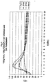
- the mold temperature is 52 ° C and gelation occurs 50 ° C after about a minute.
- Figure 2 shows that calculated using 0.38% inhibitor in terms of the amount of body resin (pure resin), a longer one Gel time has been obtained.
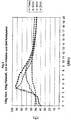
- Fig. 3 shows that by using inhibitor gelling arrives in the top after about four minutes.
- Figure 4 shows that calculated using 0.61% inhibitor no longer gel time in relation to the amount of body resin is obtained than in the case of FIG. 3.
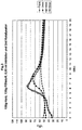
- Fig. 5 shows that no heat is generated if too much Inhibitor is used.
- Fig. 6 shows a similar reaction when the amount of catalyst is reduced.
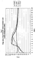
- Fig. 7 shows that heat is generated when the Mold temperature is increased. In practice, this corresponds to spraying with hot water on the die.
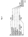
- Fig. 8 shows the arrangement of the necessary mixers an injection machine.
- M-1 is the mixer at the very front, where with with the help of two catalyst pumps P-1 and P-2 catalysts be mixed into the resins.
- M-2 is the mixer where accelerators, e.g. Co-accelerator, mixed into the body resin becomes.
- M-3 is the mixer where accelerator in the liner resin (Pure resin as the main component in the top layer inside the Tube) is mixed.
- M-4 is the mixer in the back of the injection machine, where inhibitor is mixed into the body resin.
- FIG. 9 shows the structure of a plant with 8 processing stations. 9 (a) illustrates the injection and FIG. 9 (b) taking off.
- mixer M-2 the body resin co-accelerator with 1% Co added.
- Mixer M-4 contains 0.5% inhibitor, consisting of 10% butyl catechol, added.
- a pipe with DN 800 PN 10 [nominal diameter of 800 mm, nominal pressure of 9.8 bar] is manufactured as follows:
- catalyst 1.5% catalyst is used in all layers, with different ratios of acetone-acetyl peroxide (AAP) and tertiary butyl perbenzoate (TBPB) used as follows: layer AAP TBPB Co in M-2 1 50% 50% 0.5% 2 40% 60% 0.7% 3 30% 70% 0.7% 4 50% 50% 0.8% 5 30% 70% 0.6% 6 25% 75% 0.5% 7 20% 80% - AAP is more reactive than TBPB. It has a lower light off temperature.
- AAP acetone-acetyl peroxide
- TBPB tertiary butyl perbenzoate
- the injection time is 6 minutes and the die temperature 35 ° C. After the raw materials have been brought in, the car brings them Die on station F in Fig. 9, where after 4 minutes all Have gelatinized layers and with hot water at 70 ° C during Is injected for 30 seconds.
- station F After 5 minutes in station F, the die is brought to station G and after 4 minutes to station H, where hot water at 70 ° C is sprayed for 20 seconds. In station H the undressing is prepared. After 4 minutes, the die is brought to station D, where the tube is pulled out warm.
- the water from the collecting tanks is separated without Cold and hot water are collected in a fixed channel and closed the water treatment system in a pipeline.
- the setting of the resin reaction is so fast that in the tube the reaction in the outer part increases to about 70 ° C and in the inner part to 90 to 110 ° C. Splashing with hot water should prevent that the lower die temperature is the reaction in the outer part prevented.
- the DN 600 die comes into the Injection station E, the die DN 800 must be in station G and if the die DN 500 is in station E, the Die DN 800 in station G.
- the die DN 800 is in station H when the die DN 400 is in station E.
- the heat capacity the die and the die mass on the trolley can Hot water or cold water is used in stations F to H. become.
- the eight stations of the system shown in FIG. 9 allow that the pipes are always pulled out at station D. However, are only seven stations available, the pipe DN 800 must be in station G and the other pipes must be pulled out in station C. become. Station D is then used for the injection.
- polyester resins with filler these have an enthalpy of 350 joules. It is also appropriate filler to be used in the inner pipe wall, see Layers Nos. 4 to 6 in Fig. 11.
- the pipe 12 shows the construction of a second example of a pipe according to the invention.
- the pipe has a multi-layer pipe DN 2000 (nominal width 2,000 mm), PN 16 (nominal pressure 15.7 bar), SN 10,000 (nominal rigidity 10,000 N / m 2 ).
- the roving length is 60 mm.
- FIG. 13 The construction of a third example of a pipe according to the invention is illustrated in FIG. 13.
- the pipe is a multi-layer pipe DN 2,400 (nominal width 2,400 mm), PN 10 (nominal pressure 9.8 bar), SN 5,000 (nominal rigidity 5,000 N / m 2 ).
- the roving length is 100 mm.
- the gel time in the individual layers must be dependent of the injection time can be set exactly. That in Fig. 13
- the illustrated tube takes an injection time of 23 minutes. This means that the gel time for layer # 1 is at least Must be at room temperature for 23 minutes whether the die and Raw materials are at room temperature.
- the injection time for Layer # 2 is 2.5 minutes. This means that the gel time for these layers is at least 20.5 minutes. Similar the calculation must be carried out for each shift. Based on laboratory tests, the quantities for each shift must be of the additives are recalculated.
Landscapes
- Engineering & Computer Science (AREA)
- Mechanical Engineering (AREA)
- Moulding By Coating Moulds (AREA)
- Reinforced Plastic Materials (AREA)
- Compositions Of Macromolecular Compounds (AREA)
- Processing And Handling Of Plastics And Other Materials For Molding In General (AREA)
- Glass Compositions (AREA)
- Rigid Pipes And Flexible Pipes (AREA)
- Laminated Bodies (AREA)
Description
| Glasfasergehalt (%) | exotherme Temperatur (°C) |
| 0 | 181 |
| 30 | 155 |
| 40 | 144 |
| 50 | 121 |
| 60 | 116 |
| 60 | 116 |
| 70 | 99 |
| 80 | 78 |
- Fig. 1
- bis 7 Diagramme, die den Temperaturverlauf mit der Zeit für die Form und Rohre mit unterschiedlichen Wanddicken für unterschiedliche Schichten und unterschiedliche Inhibitormengenanteile zeigt,
- Fig. 8
- ein Beispiel für die Anordnung von Mischern auf einer nach dem erfindungsgemäßen Verfahren arbeitenden Einspritzmaschine zur Herstellung geschleuderter glasfaserverstärkter Kunststoffrohre,
- Fig. 9
- eine schematische Ansicht des Aufbaus einer Anlage mit Verarbeitungsstationen A bis H für die Herstellung geschleuderter glasfaserverstärkter Kunststoffrohre,
- Fig 10
- eine schematische Ansicht des Aufbaus einer Anlage mit Verarbeitungsstationen A bis G für die Herstellung geschleuderter glasfaserverstärkter Kunststoffrohre,
- Fig. 11
- bis 13 den Aufbau von Rohren für verschiedene Nennweiten und Nenndrücke und
- Fig. 14
- ein Diagramm, das den Temperaturverlauf mit der Zeit innen im Rohr und außen auf der Matrize zeigt.
| Schicht | AAP | TBPB | Co in M-2 |
| 1 | 50% | 50% | 0,5% |
| 2 | 40% | 60% | 0,7% |
| 3 | 30% | 70% | 0,7% |
| 4 | 50% | 50% | 0,8% |
| 5 | 30% | 70% | 0,6% |
| 6 | 25% | 75% | 0,5% |
| 7 | 20% | 80% | - |
| AAP ist mehr reaktiv als TBPB. Es hat eine niedrigere Anspringtemperatur. |
Claims (23)
- Verfahren zur Herstellung von geschleuderten glasfaserverstärkten Kunststoffrohren, wobei flüssiges aushärtbares Harz, welches einen Füllstoff enthalten kann, zusammen mit Glasfasern und Additiven für die Aushärtung, möglicherweise auch mit Sand, in eine rotierende Matrize eingebracht wird,
dadurch gekennzeichnet, daß
die Additive mit Hinsicht auf die Matrizentemperatur während des Einbringens von Rohstoffen in Menge und Art sukzessiv abgestimmt werden, so daß das Gelieren im Außenteil des Rohres anfängt, wenn der letzte Teil von Rohstoffen eingebracht wird,
die Temperatur beim Gelieren niedriger im Außenteil ist als im Innenteil, und
das Gelieren im Innenteil des Rohres erst anfängt, nachdem alle Rohstoffe eingebracht worden sind. - Verfahren nach Anspruch 1, dadurch gekennzeichnet, daß das Gelieren im Außenteil erst mindestens drei Minuten anfängt, nachdem alle Rohstoffe eingebracht worden sind.
- Verfahren nach Anspruch 1 oder 2, dadurch gekennzeichnet, daß Warmwasser mit einer Temperatur von mindestens 50°C auf die Matrize gespritzt wird, nachdem das Gelieren in der Außenschicht des Rohres angefangen hat.
- Verfahren nach einem der Ansprüche 1 bis 3, dadurch gekennzeichnet, daß Inhibitor verwendet wird in einer Menge, welche zwischen 38% und 61% von der Menge liegt, welche eine Wärmeentwicklung verhindert.
- Verfahren nach einem der Ansprüche 1 bis 4, dadurch gekennzeichnet, daß eine mehr reaktive Katalysatormischung im Außenteil des Rohres verwendet wird als im Innenteil des Rohres.
- Verfahren nach einem der Ansprüche 1 bis 5, dadurch gekennzeichnet, daß Inhibitor in einem der Mischer im Feeder zugesetzt wird.
- Verfahren nach einem der Ansprüche 1 bis 6, dadurch gekennzeichnet, daß Akzelerator im zweiten Mischer (M-2) vorne im Feeder zum Bodyharz zugesetzt wird.
- Verfahren nach einem der Ansprüche 1 bis 7, dadurch gekennzeichnet, daß Akzelerator im dritten Mischer (M-3) vorne zum Linerharz zugesetzt wird.
- Verfahren nach einem der Ansprüche 1 bis 8, dadurch gekennzeichnet, daß Inhibitor zum Bodyharz hinten im Mischer (M-4) zugesetzt wird.
- Verfahren nach einem der Ansprüche 1 bis 9, wobei zwei Katalysatorpumpen verwendet werden, dadurch gekennzeichnet, daß in der einen Pumpe ein Katalysator oder eine Katalysatormischung mit niedriger Anspringtemperatur im Außenteil des Rohres verwendet wird und der andere im Innenteil des Rohres.
- Verfahren nach einem der Ansprüche 1 bis 10, dadurch gekennzeichnet, daß die Sandmenge, welche für das Erreichen der Steifigkeit notwendig ist, auf mehrere Schichten aufgeteilt wird, so daß alle Glasfaserschichten, ausgenommen die Sperrschicht, zwischen den Sandschichten positioniert sind, in welchen der Gehalt an Roving durch die Pressung der Sandschichten unter der Einwirkung Zentrifugalkraft erhöht wird.
- Verfahren nach Anspruch 11, dadurch gekennzeichnet, daß die einzelnen Sandschichten, ausgenommen die Sandschicht in der Mitte der Rohrwand (neutrale Zone), nicht größer als 15% der Wanddicke des Rohres sind.
- Verfahren nach Anspruch 11 oder 12, dadurch gekennzeichnet, daß die einzelnen Sandschichten, ausgenommen die Sandschicht in der neutralen Zone, nicht größer als 0,0025 mal der Außendurchmesser sind.
- Verfahren nach einem der Ansprüche 11 bis 13, dadurch gekennzeichnet, daß die einzelnen Schichten mit Glasfaserarmierung nicht größer als 0,005 mal der Außendurchmesser sind.
- Verfahren nach einem der Ansprüche 11 bis 14, dadurch gekennzeichnet, daß die Schichten mit Glasfaserarmierung in Umfangsrichtung, ausgenommen die Sperrschicht, nicht kleiner als 1,5 mm und nicht größer als 3,5 mm sind.
- Anlage zur Herstellung von geschleuderten glasfaserverstärkten Kunststoffrohren, bei der
die Rohstoffe aus einer Einspritzmaschine in eine rotierende Matrize eingebracht werden,
die Einspritzmaschine in einer festen Position bewegbar ist,
die Schleudermaschinen aber auf einem Wagen montiert sind, welcher quer zu der Einspritzmaschine in derselben Ebene bewegbar ist,
zum Aufwärmen der Matrize Warmwasser verwendet wird, dadurch gekennzeichnet, daß
die Spritzvorrichtungen in festen Positionen angeordnet sind und nicht mit den Matrizen bewegbar sind und
Wasser in separaten Auffangbecken unter jeder Matrize, bewegbar mit der Matrize, aufgefangen wird und in eine feste Rinne weitergeleitet wird. - Anlage nach Anspruch 16, mit einer Einspritzmaschine für das Zubringen von Rohstoffen in die Matrizen, wobei vorne ein Mischer (M-1) für das Zubringen von Katalysatoren ist, dadurch gekennzeichnet, daß hinten in der Einspritzmaschine auch ein Mischer (M-4) für das Einbringen von weiteren Additiven in das Bodyharz vorgesehen ist.
- Anlage nach Anspruch 17, dadurch gekennzeichnet, daß vorne in der Einspritzmaschine mindestens ein weiterer Mischer (M-2 oder M-3) vorhanden ist.
- Geschleudertes glasfaserverstärktes Kunststoffrohr mit mehreren Schichten aus Glasfasern, Kunstharz, welches einen Füllstoff enthalten kann, Glasfasern, Sand und Additiven, dadurch gekennzeichnet, daß die Sandmenge, welche für das Erreichen der Steifigkeit notwendig ist, auf mehrere Schichten aufgeteilt ist, so daß alle Glasfaserschichten, ausgenommen die Sperrschicht, zwischen den Sandschichten positioniert sind, in welchen der Gehalt an Roving durch die Pressung der Sandschichten unter der Einwirkung Zentrifugalkraft erhöht worden ist, und die Sperrschicht eine mindestens zwei mm dicke Rovingschicht mit einem Glasfasergehalt unter 40% ist.
- Kunststoffrohr nach Anspruch 19, dadurch gekennzeichnet, daß die einzelnen Sandschichten, ausgenommen die Sandschicht in der Mitte der Rohrwand (neutrale Zone), nicht größer als 15 % der Wanddicke des Rohres sind.
- Kunststoffrohr nach Anspruch 19 oder 20, dadurch gekennzeichnet, daß die einzelnen Sandschichten, ausgenommen die Sandschicht in der neutralen Zone, nicht größer als 0,0025 mal der Außendurchmesser sind.
- Kunststoffrohr nach einem der Ansprüche 19 bis 21, dadurch gekennzeichnet, daß die einzelnen Schichten mit Glasfaserarmierung nicht größer als 0,005 mal der Außendurchmesser sind.
- Kunststoffrohr nach einem der Ansprüche 19 bis 22, dadurch gekennzeichnet, daß die Schichten mit Glasfaserarmierung in Umfangsrichtung, ausgenommen die Sperrschicht, nicht kleiner als 1,5 mm und nicht größer als 3,5 mm sind.
Applications Claiming Priority (3)
| Application Number | Priority Date | Filing Date | Title |
|---|---|---|---|
| DE10020642A DE10020642A1 (de) | 2000-04-27 | 2000-04-27 | Verfahren und Anlage zur Herstellung von geschleuderten glasfaserverstärkten Rohren |
| DE10020642 | 2000-04-27 | ||
| PCT/EP2001/004736 WO2001083185A2 (de) | 2000-04-27 | 2001-04-26 | Verfahren und anlage zur herstellung von geschleuderten glasfaserverstärkten rohren |
Publications (3)
| Publication Number | Publication Date |
|---|---|
| EP1278620A2 EP1278620A2 (de) | 2003-01-29 |
| EP1278620B1 true EP1278620B1 (de) | 2004-02-18 |
| EP1278620B2 EP1278620B2 (de) | 2011-08-10 |
Family
ID=7640102
Family Applications (1)
| Application Number | Title | Priority Date | Filing Date |
|---|---|---|---|
| EP01940371A Expired - Lifetime EP1278620B2 (de) | 2000-04-27 | 2001-04-26 | Verfahren zur herstellung von geschleuderten glasfaserverstärkten rohren |
Country Status (15)
| Country | Link |
|---|---|
| US (1) | US20030108697A1 (de) |
| EP (1) | EP1278620B2 (de) |
| CN (1) | CN1214907C (de) |
| AT (1) | ATE259700T1 (de) |
| AU (1) | AU7397301A (de) |
| BR (1) | BR0110602B1 (de) |
| DE (2) | DE10020642A1 (de) |
| EA (1) | EA004119B1 (de) |
| EG (1) | EG22485A (de) |
| ES (1) | ES2215905T3 (de) |
| GC (1) | GC0000223A (de) |
| MX (1) | MXPA02010463A (de) |
| PL (1) | PL363743A1 (de) |
| TR (1) | TR200401005T4 (de) |
| WO (1) | WO2001083185A2 (de) |
Families Citing this family (3)
| Publication number | Priority date | Publication date | Assignee | Title |
|---|---|---|---|---|
| DE10227578A1 (de) * | 2002-06-20 | 2004-01-08 | Börge Carlström | Verfahren zur Herstellung von glasfaserverstärkten Rohren |
| US8329219B2 (en) | 2009-12-22 | 2012-12-11 | Cook Biotech Incorporated | Methods for producing ECM-based biomaterials |
| CN109732828A (zh) * | 2019-01-25 | 2019-05-10 | 吴献忠 | 一种超级字的浇铸方法及装置 |
Family Cites Families (5)
| Publication number | Priority date | Publication date | Assignee | Title |
|---|---|---|---|---|
| NZ215525A (en) * | 1985-03-23 | 1988-07-28 | Dow Chemical Gmbh | Making fibre reinforced plastics pipes by centrifugal casting |
| MX172392B (es) † | 1988-09-23 | 1993-12-15 | Hobas Eng & Durotec Ag | Procedimiento para la fabricacion de partes para conductos de tuberia, a partir de plastico, material de relleno inorganico y fibras de vidrio asi como parte de conducto de tuberia hecho con este procedimiento |
| CH684326A5 (de) † | 1991-10-23 | 1994-08-31 | Hobas Eng Ag | Verfahren zur Herstellung eines Kunststoffrohres und Anlage zur Durchführung des Verfahrens. |
| PT790114E (pt) * | 1995-12-22 | 2000-10-31 | Hobas Eng Ag | Instalacao para producao de tubos de plastico pelo processo de moldacao centrifuga |
| AR022298A1 (es) * | 1999-01-22 | 2002-09-04 | Carlstrom Borge | Un procedimiento para la fabricacion de tubos de plastico centrifugados reforzados con fibras de vidrio, tubos de plastico centrifugados reforzados confibras de vidrio y una instalacion para la fabricacion de los mismos. |
-
2000
- 2000-04-27 DE DE10020642A patent/DE10020642A1/de not_active Withdrawn
-
2001
- 2001-04-24 GC GCP20011308 patent/GC0000223A/en active
- 2001-04-26 AT AT01940371T patent/ATE259700T1/de not_active IP Right Cessation
- 2001-04-26 MX MXPA02010463A patent/MXPA02010463A/es not_active Application Discontinuation
- 2001-04-26 PL PL01363743A patent/PL363743A1/xx unknown
- 2001-04-26 EA EA200201106A patent/EA004119B1/ru not_active IP Right Cessation
- 2001-04-26 US US10/257,941 patent/US20030108697A1/en not_active Abandoned
- 2001-04-26 ES ES01940371T patent/ES2215905T3/es not_active Expired - Lifetime
- 2001-04-26 CN CNB018086802A patent/CN1214907C/zh not_active Expired - Fee Related
- 2001-04-26 BR BRPI0110602-3A patent/BR0110602B1/pt not_active IP Right Cessation
- 2001-04-26 AU AU73973/01A patent/AU7397301A/en not_active Abandoned
- 2001-04-26 WO PCT/EP2001/004736 patent/WO2001083185A2/de not_active Ceased
- 2001-04-26 EP EP01940371A patent/EP1278620B2/de not_active Expired - Lifetime
- 2001-04-26 TR TR2004/01005T patent/TR200401005T4/xx unknown
- 2001-04-26 DE DE50101512T patent/DE50101512D1/de not_active Expired - Fee Related
- 2001-04-28 EG EG20010425A patent/EG22485A/xx active
Also Published As
| Publication number | Publication date |
|---|---|
| AU7397301A (en) | 2001-11-12 |
| WO2001083185A3 (de) | 2002-04-11 |
| DE50101512D1 (de) | 2004-03-25 |
| BR0110602A (pt) | 2003-12-30 |
| TR200401005T4 (tr) | 2004-06-21 |
| CN1426346A (zh) | 2003-06-25 |
| CN1214907C (zh) | 2005-08-17 |
| ATE259700T1 (de) | 2004-03-15 |
| GC0000223A (en) | 2006-03-29 |
| MXPA02010463A (es) | 2003-04-25 |
| WO2001083185A2 (de) | 2001-11-08 |
| EA004119B1 (ru) | 2003-12-25 |
| BR0110602B1 (pt) | 2013-01-22 |
| EP1278620A2 (de) | 2003-01-29 |
| EA200201106A1 (ru) | 2003-06-26 |
| EP1278620B2 (de) | 2011-08-10 |
| US20030108697A1 (en) | 2003-06-12 |
| DE10020642A1 (de) | 2001-10-31 |
| ES2215905T3 (es) | 2004-10-16 |
| PL363743A1 (en) | 2004-11-29 |
| EG22485A (en) | 2003-02-26 |
Similar Documents
| Publication | Publication Date | Title |
|---|---|---|
| EP0360758B1 (de) | Verfahren zur Herstellung von Rohrleitungsteilen aus Kunststoff, anorganischem Füllstoff und Glasfasern im Schleuderguss-Verfahren sowie ein nach diesem Verfahren hergestelltes Rohrleitungsteil | |
| DE69210543T2 (de) | Herstellungsverfahren zum Formen eines Verbundproduktes | |
| EP2247434B1 (de) | Verfahren und vorrichtung zur herstellung faserverstärkter kunststoffprofilteile sowie dadurch faserverstärktes kunststoffprofilteil | |
| DE3121241C2 (de) | Verfahren zum Herstellen eines Verbundkunststoffrohres aus thermoplastischem Harz | |
| EP0158623B1 (de) | Verfahren zum Herstellen einer Blattfeder aus faserverstärktem Kunststoff | |
| DE69321050T2 (de) | Strukturelement aus einem faserverstärkten thermoplastischen Material und Verfahren zu seiner Herstellung | |
| EP1631441B1 (de) | Verfahren und vorrichtung zur herstellung von dreidimensional ausgeprägten formteilen sowie formteil | |
| EP2342068B1 (de) | Verfahren und vorrichtung zur herstellung hochbelastbarer kunstoffformteile mit hohlprofil | |
| DE102011012900A1 (de) | Faserverstärktes Kunststoffverbundbauteil und dessen Herstellung | |
| DE102019108123A1 (de) | Additive Fertigungsvorrichtung, additives Fertigungsverfahren und Profilstab hierfür | |
| EP3730275A2 (de) | Verfahren zur direktcompoundierung faserverstärkter verbundwerkstoffe für das herstellen von kunststoffformteilen und direktcompoundierungsvorrichtung | |
| DE102021105316B4 (de) | Herstellungsverfahren für ein faserverstärktes Harzformprodukt | |
| CN110757841A (zh) | 一种碳纤维复合芯的生产方法 | |
| DE2422648A1 (de) | Wandaufbau aus mehreren bestandteilen | |
| EP1397239B1 (de) | Verfahren zur herstellung eines bauteils | |
| EP1278620B2 (de) | Verfahren zur herstellung von geschleuderten glasfaserverstärkten rohren | |
| EP0151930B1 (de) | Verfahren zum Herstellen eines Rohrstückes und danach hergestelltes Verbundrohr | |
| EP0158631A2 (de) | Verfahren zur Herstellung von Rohren aus faserverstärktem, härtbarem Kunststoff und Vorrichtung zur Durchführung des Verfahrens | |
| EP1187713A2 (de) | Verfahren zur herstellung von geschleuderten glasfaserverstärkten kunststoffrohren | |
| DE4341521A1 (de) | Verfahren zur Herstellung eines Produktes aus einem faserverstärkten Verbundwerkstoff | |
| DE102018111283B4 (de) | Vorrichtung, Verfahren und Verwendung der Vorrichtung zum semikontinuierlichen Blasformen faserverstärkter thermoplastischer Hohlprofile mit einem konstanten oder sich änderndem Querschnitt | |
| DE2135181C3 (de) | Herstellung von faserverstärkten, hochfesten, starren Formkörpern | |
| CN113442471A (zh) | 一种电力电缆管在线连续注射成型设备 | |
| AT411661B (de) | Langfasergranulat | |
| DE3510626C2 (de) | Schleudergußverfahren zum Herstellen von faserverstärkten Kunststoffrohren und mittels dieses Verfahrens hergestelltes faserverstärktes Kunststoffrohr |
Legal Events
| Date | Code | Title | Description |
|---|---|---|---|
| PUAI | Public reference made under article 153(3) epc to a published international application that has entered the european phase |
Free format text: ORIGINAL CODE: 0009012 |
|
| 17P | Request for examination filed |
Effective date: 20021122 |
|
| AK | Designated contracting states |
Designated state(s): AT BE CH CY DE DK ES FI FR GB GR IE IT LI LU MC NL PT SE TR |
|
| AX | Request for extension of the european patent |
Extension state: AL LT LV MK RO SI |
|
| GRAP | Despatch of communication of intention to grant a patent |
Free format text: ORIGINAL CODE: EPIDOSNIGR1 |
|
| GRAS | Grant fee paid |
Free format text: ORIGINAL CODE: EPIDOSNIGR3 |
|
| GRAA | (expected) grant |
Free format text: ORIGINAL CODE: 0009210 |
|
| AK | Designated contracting states |
Kind code of ref document: B1 Designated state(s): AT BE CH CY DE DK ES FI FR GB GR IE IT LI LU MC NL PT SE TR |
|
| AX | Request for extension of the european patent |
Extension state: AL LT LV MK RO SI |
|
| PG25 | Lapsed in a contracting state [announced via postgrant information from national office to epo] |
Ref country code: IE Free format text: LAPSE BECAUSE OF FAILURE TO SUBMIT A TRANSLATION OF THE DESCRIPTION OR TO PAY THE FEE WITHIN THE PRESCRIBED TIME-LIMIT Effective date: 20040218 Ref country code: FI Free format text: LAPSE BECAUSE OF FAILURE TO SUBMIT A TRANSLATION OF THE DESCRIPTION OR TO PAY THE FEE WITHIN THE PRESCRIBED TIME-LIMIT Effective date: 20040218 Ref country code: CY Free format text: LAPSE BECAUSE OF FAILURE TO SUBMIT A TRANSLATION OF THE DESCRIPTION OR TO PAY THE FEE WITHIN THE PRESCRIBED TIME-LIMIT Effective date: 20040218 |
|
| REG | Reference to a national code |
Ref country code: GB Ref legal event code: FG4D Free format text: NOT ENGLISH |
|
| REG | Reference to a national code |
Ref country code: CH Ref legal event code: EP |
|
| REG | Reference to a national code |
Ref country code: IE Ref legal event code: FG4D Free format text: GERMAN |
|
| REF | Corresponds to: |
Ref document number: 50101512 Country of ref document: DE Date of ref document: 20040325 Kind code of ref document: P |
|
| PGFP | Annual fee paid to national office [announced via postgrant information from national office to epo] |
Ref country code: FR Payment date: 20040421 Year of fee payment: 4 |
|
| PGFP | Annual fee paid to national office [announced via postgrant information from national office to epo] |
Ref country code: AT Payment date: 20040423 Year of fee payment: 4 Ref country code: MC Payment date: 20040423 Year of fee payment: 4 |
|
| PGFP | Annual fee paid to national office [announced via postgrant information from national office to epo] |
Ref country code: LU Payment date: 20040426 Year of fee payment: 4 |
|
| PG25 | Lapsed in a contracting state [announced via postgrant information from national office to epo] |
Ref country code: BE Free format text: LAPSE BECAUSE OF NON-PAYMENT OF DUE FEES Effective date: 20040430 |
|
| PGFP | Annual fee paid to national office [announced via postgrant information from national office to epo] |
Ref country code: GR Payment date: 20040430 Year of fee payment: 4 |
|
| PG25 | Lapsed in a contracting state [announced via postgrant information from national office to epo] |
Ref country code: SE Free format text: LAPSE BECAUSE OF FAILURE TO SUBMIT A TRANSLATION OF THE DESCRIPTION OR TO PAY THE FEE WITHIN THE PRESCRIBED TIME-LIMIT Effective date: 20040518 Ref country code: DK Free format text: LAPSE BECAUSE OF FAILURE TO SUBMIT A TRANSLATION OF THE DESCRIPTION OR TO PAY THE FEE WITHIN THE PRESCRIBED TIME-LIMIT Effective date: 20040518 |
|
| REG | Reference to a national code |
Ref country code: CH Ref legal event code: NV Representative=s name: DR. JOACHIM LAUER |
|
| REG | Reference to a national code |
Ref country code: GR Ref legal event code: EP Ref document number: 20040401648 Country of ref document: GR |
|
| GBT | Gb: translation of ep patent filed (gb section 77(6)(a)/1977) |
Effective date: 20040617 |
|
| LTIE | Lt: invalidation of european patent or patent extension |
Effective date: 20040218 |
|
| REG | Reference to a national code |
Ref country code: IE Ref legal event code: FD4D |
|
| REG | Reference to a national code |
Ref country code: ES Ref legal event code: FG2A Ref document number: 2215905 Country of ref document: ES Kind code of ref document: T3 |
|
| BERE | Be: lapsed |
Owner name: C-TECH LTD. Effective date: 20040430 |
|
| PLBQ | Unpublished change to opponent data |
Free format text: ORIGINAL CODE: EPIDOS OPPO |
|
| ET | Fr: translation filed | ||
| PLBI | Opposition filed |
Free format text: ORIGINAL CODE: 0009260 |
|
| PLAX | Notice of opposition and request to file observation + time limit sent |
Free format text: ORIGINAL CODE: EPIDOSNOBS2 |
|
| 26 | Opposition filed |
Opponent name: HOBAS ENGINEERING GMBH Effective date: 20041109 |
|
| RAP2 | Party data changed (patent owner data changed or rights of a patent transferred) |
Owner name: CALDERO TRUST REG. |
|
| NLR1 | Nl: opposition has been filed with the epo |
Opponent name: HOBAS ENGINEERING GMBH |
|
| NLT2 | Nl: modifications (of names), taken from the european patent patent bulletin |
Owner name: CALDERO TRUST REG. |
|
| PGFP | Annual fee paid to national office [announced via postgrant information from national office to epo] |
Ref country code: ES Payment date: 20050421 Year of fee payment: 5 |
|
| PG25 | Lapsed in a contracting state [announced via postgrant information from national office to epo] |
Ref country code: AT Free format text: LAPSE BECAUSE OF NON-PAYMENT OF DUE FEES Effective date: 20050426 Ref country code: GB Free format text: LAPSE BECAUSE OF NON-PAYMENT OF DUE FEES Effective date: 20050426 Ref country code: LU Free format text: LAPSE BECAUSE OF NON-PAYMENT OF DUE FEES Effective date: 20050426 |
|
| PG25 | Lapsed in a contracting state [announced via postgrant information from national office to epo] |
Ref country code: MC Free format text: LAPSE BECAUSE OF NON-PAYMENT OF DUE FEES Effective date: 20050430 Ref country code: LI Free format text: LAPSE BECAUSE OF NON-PAYMENT OF DUE FEES Effective date: 20050430 Ref country code: CH Free format text: LAPSE BECAUSE OF NON-PAYMENT OF DUE FEES Effective date: 20050430 |
|
| PLAX | Notice of opposition and request to file observation + time limit sent |
Free format text: ORIGINAL CODE: EPIDOSNOBS2 |
|
| PGFP | Annual fee paid to national office [announced via postgrant information from national office to epo] |
Ref country code: DE Payment date: 20050629 Year of fee payment: 5 |
|
| PLBB | Reply of patent proprietor to notice(s) of opposition received |
Free format text: ORIGINAL CODE: EPIDOSNOBS3 |
|
| PG25 | Lapsed in a contracting state [announced via postgrant information from national office to epo] |
Ref country code: NL Free format text: LAPSE BECAUSE OF NON-PAYMENT OF DUE FEES Effective date: 20051101 |
|
| PG25 | Lapsed in a contracting state [announced via postgrant information from national office to epo] |
Ref country code: GR Free format text: LAPSE BECAUSE OF NON-PAYMENT OF DUE FEES Effective date: 20051103 |
|
| REG | Reference to a national code |
Ref country code: CH Ref legal event code: PL |
|
| GBPC | Gb: european patent ceased through non-payment of renewal fee |
Effective date: 20050426 |
|
| PG25 | Lapsed in a contracting state [announced via postgrant information from national office to epo] |
Ref country code: FR Free format text: LAPSE BECAUSE OF NON-PAYMENT OF DUE FEES Effective date: 20051230 |
|
| NLV4 | Nl: lapsed or anulled due to non-payment of the annual fee |
Effective date: 20051101 |
|
| REG | Reference to a national code |
Ref country code: FR Ref legal event code: ST Effective date: 20051230 |
|
| PG25 | Lapsed in a contracting state [announced via postgrant information from national office to epo] |
Ref country code: ES Free format text: LAPSE BECAUSE OF NON-PAYMENT OF DUE FEES Effective date: 20060427 |
|
| RDAF | Communication despatched that patent is revoked |
Free format text: ORIGINAL CODE: EPIDOSNREV1 |
|
| PG25 | Lapsed in a contracting state [announced via postgrant information from national office to epo] |
Ref country code: DE Free format text: LAPSE BECAUSE OF NON-PAYMENT OF DUE FEES Effective date: 20061101 |
|
| APAH | Appeal reference modified |
Free format text: ORIGINAL CODE: EPIDOSCREFNO |
|
| APBP | Date of receipt of notice of appeal recorded |
Free format text: ORIGINAL CODE: EPIDOSNNOA2O |
|
| APBQ | Date of receipt of statement of grounds of appeal recorded |
Free format text: ORIGINAL CODE: EPIDOSNNOA3O |
|
| REG | Reference to a national code |
Ref country code: ES Ref legal event code: FD2A Effective date: 20060427 |
|
| PG25 | Lapsed in a contracting state [announced via postgrant information from national office to epo] |
Ref country code: PT Free format text: LAPSE BECAUSE OF NON-PAYMENT OF DUE FEES Effective date: 20040718 |
|
| RAP2 | Party data changed (patent owner data changed or rights of a patent transferred) |
Owner name: C-TECH LTD. |
|
| APBU | Appeal procedure closed |
Free format text: ORIGINAL CODE: EPIDOSNNOA9O |
|
| PG25 | Lapsed in a contracting state [announced via postgrant information from national office to epo] |
Ref country code: IT Free format text: LAPSE BECAUSE OF NON-PAYMENT OF DUE FEES Effective date: 20080426 |
|
| RTI2 | Title (correction) |
Free format text: METHOD FOR PRODUCING CENTRIFUGALLY CAST, GLASS-FIBRE REINFORCED TUBES |
|
| PUAH | Patent maintained in amended form |
Free format text: ORIGINAL CODE: 0009272 |
|
| STAA | Information on the status of an ep patent application or granted ep patent |
Free format text: STATUS: PATENT MAINTAINED AS AMENDED |
|
| 27A | Patent maintained in amended form |
Effective date: 20110810 |
|
| AK | Designated contracting states |
Kind code of ref document: B2 Designated state(s): AT BE CH CY DE DK ES FI FR GB GR IE IT LI LU MC NL PT SE TR |
|
| AX | Request for extension of the european patent |
Extension state: AL LT LV MK RO SI |
|
| REG | Reference to a national code |
Ref country code: DE Ref legal event code: R102 Ref document number: 50101512 Country of ref document: DE Effective date: 20110810 |
|
| PGFP | Annual fee paid to national office [announced via postgrant information from national office to epo] |
Ref country code: TR Payment date: 20170426 Year of fee payment: 17 |
|
| PGFP | Annual fee paid to national office [announced via postgrant information from national office to epo] |
Ref country code: IT Payment date: 20170420 Year of fee payment: 17 |
|
| PG25 | Lapsed in a contracting state [announced via postgrant information from national office to epo] |
Ref country code: IT Free format text: LAPSE BECAUSE OF NON-PAYMENT OF DUE FEES Effective date: 20180426 |
|
| PG25 | Lapsed in a contracting state [announced via postgrant information from national office to epo] |
Ref country code: TR Free format text: LAPSE BECAUSE OF NON-PAYMENT OF DUE FEES Effective date: 20180426 |