EP1277918B1 - Double-wall blade for a variable geometry turbine nozzle - Google Patents
Double-wall blade for a variable geometry turbine nozzle Download PDFInfo
- Publication number
- EP1277918B1 EP1277918B1 EP02015938A EP02015938A EP1277918B1 EP 1277918 B1 EP1277918 B1 EP 1277918B1 EP 02015938 A EP02015938 A EP 02015938A EP 02015938 A EP02015938 A EP 02015938A EP 1277918 B1 EP1277918 B1 EP 1277918B1
- Authority
- EP
- European Patent Office
- Prior art keywords
- wall
- blade according
- duct
- blade
- intake
- Prior art date
- Legal status (The legal status is an assumption and is not a legal conclusion. Google has not performed a legal analysis and makes no representation as to the accuracy of the status listed.)
- Expired - Lifetime
Links
- 238000001816 cooling Methods 0.000 claims description 29
- 239000012809 cooling fluid Substances 0.000 claims 5
- 238000000926 separation method Methods 0.000 claims 1
- 239000007789 gas Substances 0.000 description 9
- 239000000463 material Substances 0.000 description 6
- 230000035882 stress Effects 0.000 description 2
- 238000011144 upstream manufacturing Methods 0.000 description 2
- 238000005219 brazing Methods 0.000 description 1
- 229910010293 ceramic material Inorganic materials 0.000 description 1
- 238000010276 construction Methods 0.000 description 1
- 230000001419 dependent effect Effects 0.000 description 1
- 238000001914 filtration Methods 0.000 description 1
- 239000012530 fluid Substances 0.000 description 1
- 238000010438 heat treatment Methods 0.000 description 1
- 238000003780 insertion Methods 0.000 description 1
- 230000037431 insertion Effects 0.000 description 1
- 238000012986 modification Methods 0.000 description 1
- 230000004048 modification Effects 0.000 description 1
- 230000001105 regulatory effect Effects 0.000 description 1
- 238000005728 strengthening Methods 0.000 description 1
- 230000008646 thermal stress Effects 0.000 description 1
Images

Classifications
-
- F—MECHANICAL ENGINEERING; LIGHTING; HEATING; WEAPONS; BLASTING
- F01—MACHINES OR ENGINES IN GENERAL; ENGINE PLANTS IN GENERAL; STEAM ENGINES
- F01D—NON-POSITIVE DISPLACEMENT MACHINES OR ENGINES, e.g. STEAM TURBINES
- F01D5/00—Blades; Blade-carrying members; Heating, heat-insulating, cooling or antivibration means on the blades or the members
- F01D5/12—Blades
- F01D5/14—Form or construction
- F01D5/18—Hollow blades, i.e. blades with cooling or heating channels or cavities; Heating, heat-insulating or cooling means on blades
- F01D5/187—Convection cooling
-
- F—MECHANICAL ENGINEERING; LIGHTING; HEATING; WEAPONS; BLASTING
- F01—MACHINES OR ENGINES IN GENERAL; ENGINE PLANTS IN GENERAL; STEAM ENGINES
- F01D—NON-POSITIVE DISPLACEMENT MACHINES OR ENGINES, e.g. STEAM TURBINES
- F01D17/00—Regulating or controlling by varying flow
- F01D17/10—Final actuators
- F01D17/12—Final actuators arranged in stator parts
- F01D17/14—Final actuators arranged in stator parts varying effective cross-sectional area of nozzles or guide conduits
- F01D17/16—Final actuators arranged in stator parts varying effective cross-sectional area of nozzles or guide conduits by means of nozzle vanes
- F01D17/162—Final actuators arranged in stator parts varying effective cross-sectional area of nozzles or guide conduits by means of nozzle vanes for axial flow, i.e. the vanes turning around axes which are essentially perpendicular to the rotor centre line
-
- F—MECHANICAL ENGINEERING; LIGHTING; HEATING; WEAPONS; BLASTING
- F01—MACHINES OR ENGINES IN GENERAL; ENGINE PLANTS IN GENERAL; STEAM ENGINES
- F01D—NON-POSITIVE DISPLACEMENT MACHINES OR ENGINES, e.g. STEAM TURBINES
- F01D9/00—Stators
- F01D9/02—Nozzles; Nozzle boxes; Stator blades; Guide conduits, e.g. individual nozzles
- F01D9/04—Nozzles; Nozzle boxes; Stator blades; Guide conduits, e.g. individual nozzles forming ring or sector
- F01D9/041—Nozzles; Nozzle boxes; Stator blades; Guide conduits, e.g. individual nozzles forming ring or sector using blades
-
- F—MECHANICAL ENGINEERING; LIGHTING; HEATING; WEAPONS; BLASTING
- F05—INDEXING SCHEMES RELATING TO ENGINES OR PUMPS IN VARIOUS SUBCLASSES OF CLASSES F01-F04
- F05D—INDEXING SCHEME FOR ASPECTS RELATING TO NON-POSITIVE-DISPLACEMENT MACHINES OR ENGINES, GAS-TURBINES OR JET-PROPULSION PLANTS
- F05D2240/00—Components
- F05D2240/80—Platforms for stationary or moving blades
- F05D2240/81—Cooled platforms
-
- F—MECHANICAL ENGINEERING; LIGHTING; HEATING; WEAPONS; BLASTING
- F05—INDEXING SCHEMES RELATING TO ENGINES OR PUMPS IN VARIOUS SUBCLASSES OF CLASSES F01-F04
- F05D—INDEXING SCHEME FOR ASPECTS RELATING TO NON-POSITIVE-DISPLACEMENT MACHINES OR ENGINES, GAS-TURBINES OR JET-PROPULSION PLANTS
- F05D2260/00—Function
- F05D2260/20—Heat transfer, e.g. cooling
- F05D2260/201—Heat transfer, e.g. cooling by impingement of a fluid
-
- F—MECHANICAL ENGINEERING; LIGHTING; HEATING; WEAPONS; BLASTING
- F05—INDEXING SCHEMES RELATING TO ENGINES OR PUMPS IN VARIOUS SUBCLASSES OF CLASSES F01-F04
- F05D—INDEXING SCHEME FOR ASPECTS RELATING TO NON-POSITIVE-DISPLACEMENT MACHINES OR ENGINES, GAS-TURBINES OR JET-PROPULSION PLANTS
- F05D2260/00—Function
- F05D2260/20—Heat transfer, e.g. cooling
- F05D2260/221—Improvement of heat transfer
- F05D2260/2214—Improvement of heat transfer by increasing the heat transfer surface
- F05D2260/22141—Improvement of heat transfer by increasing the heat transfer surface using fins or ribs
-
- Y—GENERAL TAGGING OF NEW TECHNOLOGICAL DEVELOPMENTS; GENERAL TAGGING OF CROSS-SECTIONAL TECHNOLOGIES SPANNING OVER SEVERAL SECTIONS OF THE IPC; TECHNICAL SUBJECTS COVERED BY FORMER USPC CROSS-REFERENCE ART COLLECTIONS [XRACs] AND DIGESTS
- Y02—TECHNOLOGIES OR APPLICATIONS FOR MITIGATION OR ADAPTATION AGAINST CLIMATE CHANGE
- Y02T—CLIMATE CHANGE MITIGATION TECHNOLOGIES RELATED TO TRANSPORTATION
- Y02T50/00—Aeronautics or air transport
- Y02T50/60—Efficient propulsion technologies, e.g. for aircraft
Definitions
- the present invention relates to a double-wall blade for a turbine, particularly for aeronautical applications.
- a blade for a gas turbine of an aeronautical engine has an axis which is incident with the axis of the turbine and has a streamlined profile defined by a lateral wall, which, in use, is lapped by gas at a relatively high temperature and must therefore be continually cooled, for example by means of air obtained from a compressor disposed upstream from the turbine, in order to limit firstly the thermal stresses and secondly the mechanical stresses caused by the thermal expansion of the lateral wall itself.
- Blades of the so-called "double-wall” type are known, in which the lateral wall comprises an outer wall and an inner wall, which are opposite, spaced from and integral with one another.
- the need exists to provide a blade which has regular efficiency of heat exchange along the lateral wall, for example by limiting any areas of stagnation of the air which can cool the lateral wall.
- the need exists to remove different quantities of heat from amongst the various areas of the lateral wall according to a substantially predetermined map, since it is found experimentally that, in use, the lateral wall heats up differently from one area to another, in particular along the axis of the blade.
- US 4697985 and US 3574481 disclose double-wall blades comprising an outer wall and an inner wall, which is faced the outer wall and is defined by an insertion member, without continuity of material with the outer wall.
- US 3373970 disclose a double wall blade, according to the preamble of claim 1, in which the outer and inner walls can be integral to one another.
- the object of the present invention is to provide a double-wall blade for a turbine, particularly for aeronautical applications, which makes it possible to fulfil the above-described requirements simply and relatively economically.
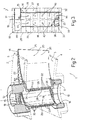
- FIG. 1 indicates as a whole a blade, in particular a blade of a stator 2 (illustrated partially and schematically) in an axial gas turbine with variable geometry for an aeronautical engine, to which the following description refers explicitly without detracting from generality.
- the stator 2 defines an annular duct 3 (partially illustrated), which is provided around the axis of the turbine (not illustrated) and through which, in use, expanding gas at a high temperature passes and which is delimited radially by a pair of platforms 4,5 opposite one another, which support a row of blades 1.
- the blade 1 has its own axis 10 which is incident with the axis of the turbine and comprises two opposite end portions 11,12, which are coaxial to one another along the axis 10 and are pivoted respectively on the platforms 4 and 5, in order to allow the blade 1 to rotate around the axis 10 itself in order to vary the capacity or geometry of the stator 2, and thus the flow rate of the gases which pass through the stator 2 itself.
- the blade 1 additionally comprises an intermediate axial portion 14, which is integral with the portions 11,12, extends along the axis 10 in the duct 3 and delimits two inner cavities 15,16, which are separated from one another by a wall 17 parallel to the axis 10, and from which the cavity 15 extends along the axis 10 itself and communicates with the exterior via two axial passages 18 provided in the portions 11,12.
- the portion 14 comprises a lateral wall 20 and a pair of end walls 21,22 which are disposed at the opposite axial ends of the lateral wall 20, transverse to the axis 10, delimit the cavity 16 axially and are connected in a sliding manner to the platforms 4 and 5 respectively.
- the lateral wall 20 surrounds the axis 10, is lapped in use by the gases which flow in the duct 3 and defines a streamlined profile which has a leading edge 24, a trailing edge 25, and a side or surface 26 which is subjected to pressure and is concave towards the exterior, and a side or surface 27 which is subjected to low pressure, and is convex towards the exterior, which sides extend between the leading edge 24 and the trailing edge 25.
- the blade 1 is of the so-called "double-wall” type, i.e. the lateral wall 20 comprises an inner wall 28 and an outer wall 29, which face one another and are integral with one another.
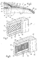
- the walls 28,29 are spaced from one another by a distance which is substantially equal to their thickness, measured along a direction at right-angles to the walls 28,29 themselves, and are connected to one another by a number of baffles 32 disposed on planes which are parallel to one another and at right-angles to the axis 10.
- the baffles 32 separate from one another axially a number of ducts 33, which have the same cross-section of passage, extend around the axis 10 tangentially to the walls 28,29 and constitute part of channelling 34 which also comprises the cavities 15,16 and, in use, can convey cooling air through the blade 1.
- the baffles 32 are intersected by a baffle 35, which extends axially along the leading edge 24 and projects from the outer wall 29 towards the interior in order to divide the ducts 33 into a number of ducts 36 provided along the side 26 which is subjected to pressure and into a number of ducts 37 which are provided along the side 27 which is subjected to low pressure.
- the ducts 36,37 have respective intakes 38,39, which are provided in the wall 28 along two rows parallel to the axis 10, communicate with the cavity 15 and are separated from one another by the baffles 35 and 32 in order, in use, to allow a corresponding flow of cooling air which is distinct from the other flows to pass through each duct 36,37.
- a plate-type element 44 which is connected integrally to the inner wall 28, preferably by means of brazing, and for each intake 38,39 has a corresponding circular through hole 45,46.
- the cross-sections of passage of the holes 45,46 have respective diameters which differ from one another and are calibrated according to the flow rate of cooling air which is to be made to flow through each duct 36,37.
- the inner wall 28 and outer wall 29 have respective surfaces 48,49 which are opposite one another in order to delimit the ducts 36,37 and support a number of turbulence generators which can interrupt the final layer of the flow of cooling air along the surfaces 48,49 themselves.
- These turbulence generators are transverse to a direction S of advance of the flow of cooling air of the duct 33 and are defined according to figure 6 by ribs 51, or according to the variation in figure 7 by incisions 52 provided along the surfaces 48,49.
- each duct 36,37 ends in a corresponding main outlet 54, which is aligned with the duct 36,37 itself and communicates with a slot 55 provided in a tail portion 56 of the blade 1.
- the slot 55 constitutes part of the channelling 34, is delimited by the end walls 21,22 and by two flat surfaces 58 of the outer wall 29, opens along the outlet edge 25 through a number of ducts 59 and accommodates a number of cylindrical portions or tabs 60, which connect the surfaces 58 to one another.
- each duct 36,37 has a corresponding secondary outlet 61 (figure 1), which is provided through the inner wall 28 in order to open into the cavity 16, whereas the channelling 34 comprises a number of through holes 64 which are provided in the end walls 21,22 and communicate with the cavity 16 in order, in use, to convey the cooling air which is obtained from the outlets 61 and to cool the areas of connection between the end walls 21,22 and the platforms 4,5.
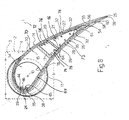
- FIG. 8 shows a blade 1a, the component parts of which are indicated, where possible, using the same reference numbers as for blade 1.
- Blade 1a differs from blade 1 by portion 14 comprising, in addition to cavity 15,16, an intermediate chamber 66 separated from cavity 15 by a wall 17, and from cavity 16 by a wall 67 substantially parallel to wall 17.
- each duct 36,37 comprises a relative first portion 69,70 terminating inside chamber 66 through an outlet 71,72 formed in inner wall 28; and a relative second portion 73,74 which extends from chamber 66 through a relative intake 75,76 formed in inner wall 28, and terminates with outlets 54,61.
- the cooling air which is obtained for example from a compressor disposed upstream from the turbine, is conveyed in a manner which is known and is not described in detail through a passage 18 in the cavity 15, from which it enters into each duct 36,37 through the corresponding hole 45,46 and the corresponding intake 38,39.
- each duct 36, 37 there flows a corresponding flow of cooling air, the flow rate of which is substantially constant and equal to a value which is dependent on the calibrated cross-section of the corresponding hole 45,46, which is established a priori for the same pressure difference between the cavity 15 and the outlets 54,61 and in regular thermal conditions.
- the baffles 32 are therefore formed in one piece with walls 28,29 (figure 2) and transmit heat by means of conduction from the outer wall 29 which is lapped by the gases towards the inner wall 28, whereas the cooling air flows in the ducts 36,37 tangentially to the baffles 32 and to the inner wall 28 and outer wall 29, thus removing heat by convection.
- the part of the cooling air which flows from the outlets 61 enters into the cavity 16 and passes through the through holes 64 in order to form between the platforms 4,5 and the walls 21,22 a veil of air, which is particularly, but not exclusively suitable for turbines with variable geometry, since, as well as carrying out a cooling function, it prevents the gases from filtering between the platforms 4,5 and the walls 21,22 on the side 26 which is subjected to pressure, towards the side 27 which is subjected to low pressure.
- the part of the cooling air which flows from the outlets 53 flows into the slot 55 tangentially to the surfaces 58 and around the cylindrical portions 60 in order to remove heat by convection from the tail portion 56 until it is output into the duct 3.
- the cylindrical portions 60 define respective thermal bridges which transmit heat by conduction between the surfaces 58.
- the channelling 34 makes it possible to cool the blade 1,1a such as to obtain a substantially regular range of temperatures along the lateral wall 20.
- the channelling 34 makes it possible to make flows of cooling air flow along a direction of advance S which is tangential to the baffles 32 and to the walls 28,29, such that the efficiency of heat exchange between the cooling air itself and the lateral wall 20 is relatively high, in particular in comparison with other solutions in which transverse jets of air are provided which cover the lateral wall of the blade.
- the efficiency of heat exchange is regular between the various areas of the lateral wall 20, since the ducts 33 have respective intakes and outlets which are different from one another, and thus convey flows of air which are different from one another and are free from localised losses of load or areas of stagnation, caused for example by any elbowed sections, in relation to the flows of air themselves.
- baffles 32 (figure 2) contributes towards making ducts 33 along axis 10 airtight and therefore independent of one another, and permits material continuity between walls 28,29, so that the heat from the gases in duct 3 flows by conduction from outer wall 29 to inner wall 28 in the material interposed axially between ducts 33, the only thermal resistance being the conductivity of the material itself.
- baffles 32 simply rested on one of walls 28, 29, as opposed to being formed in one piece with walls 28, 29, the heat would encounter greater thermal resistance due to the inevitable, albeit minor, discontinuity of the material of baffles 32 and walls 28,29, thus reducing the amount of heat removed and impairing thermal exchange efficiency.
- the baffles 32 which are transverse to the axis 10 make it possible to differentiate from one another the various flows of air in the ducts 33 along the axis 10.
- the channelling 34 makes it possible to remove heat according to a substantially predefined map, since it is possible to establish a priori with good approximation the flow rate of the flows of air between the various ducts 36,37, by differentiating the flow rate of these flows both in the direction parallel to the axis 10 and between the side which is subjected to pressure 26 and the side which is subjected to low pressure 27.
- the flow rate of the flows of cooling air is regulated by the element 44 which can be added in a second stage to the remaining part of the blade 1,1a so as to calibrate the holes 45,46, for example according to the type of aeronautical engine and the position in which the blade 1,1a itself will be fitted.
- the ribs 51, the incisions 52 and the cylindrical portions 60 generate in the flows of cooling air turbulent motion which increases the efficiency of the heat exchange.
- blade 1a the construction characteristics of blade 1a enable it to be produced more easily in one piece.
- Blade 1a in fact, is produced using a disposable core (not shown) made of ceramic material, in the form of a negative of the material of blade 1a, and comprising an intermediate portion eventually defining chamber 66.
- a disposable core made of ceramic material, in the form of a negative of the material of blade 1a, and comprising an intermediate portion eventually defining chamber 66.
- the intermediate portion joins at an intermediate point the lateral portions of the core eventually defining ducts 36 and 37, so that the core is easier to produce and stronger than the one required for blade 1, and the lateral portions of the ducts of which are joined slely at the ends, i.e. at intakes 38,39 and outlets 54,61.
- the ducts 33 could have arrangements different from that indicated by way of example, provided that they are transverse to the axis 10, and/or dimensions different from those indicated by way of example.
- the ducts 33 could have cross-sections of passage with dimensions which differ from one another in order to have flow rates of air passing through them which differ from one another.
- cylindrical portions or tabs similar to the cylindrical portions 60 could also be provided in the ducts 33.
- channelling 34 could also be provided in a fixed stator blade or in a rotor blade.
Landscapes
- Engineering & Computer Science (AREA)
- Mechanical Engineering (AREA)
- General Engineering & Computer Science (AREA)
- Turbine Rotor Nozzle Sealing (AREA)
Applications Claiming Priority (2)
| Application Number | Priority Date | Filing Date | Title |
|---|---|---|---|
| IT2001TO000704A ITTO20010704A1 (it) | 2001-07-18 | 2001-07-18 | Paletta a doppia parete per una turbina, particolarmente per applicazioni aeronautiche. |
| ITTO20010704 | 2001-07-18 |
Publications (2)
| Publication Number | Publication Date |
|---|---|
| EP1277918A1 EP1277918A1 (en) | 2003-01-22 |
| EP1277918B1 true EP1277918B1 (en) | 2007-02-21 |
Family
ID=11459061
Family Applications (1)
| Application Number | Title | Priority Date | Filing Date |
|---|---|---|---|
| EP02015938A Expired - Lifetime EP1277918B1 (en) | 2001-07-18 | 2002-07-17 | Double-wall blade for a variable geometry turbine nozzle |
Country Status (5)
| Country | Link |
|---|---|
| US (1) | US20030017051A1 (it) |
| EP (1) | EP1277918B1 (it) |
| CA (1) | CA2393979C (it) |
| DE (1) | DE60218248T2 (it) |
| IT (1) | ITTO20010704A1 (it) |
Cited By (4)
| Publication number | Priority date | Publication date | Assignee | Title |
|---|---|---|---|---|
| US8262345B2 (en) | 2009-02-06 | 2012-09-11 | General Electric Company | Ceramic matrix composite turbine engine |
| US8382436B2 (en) | 2009-01-06 | 2013-02-26 | General Electric Company | Non-integral turbine blade platforms and systems |
| US8668445B2 (en) | 2010-10-15 | 2014-03-11 | General Electric Company | Variable turbine nozzle system |
| EP3760838B1 (en) * | 2019-07-03 | 2022-12-28 | Raytheon Technologies Corporation | Gas turbine variable vane system and method |
Families Citing this family (9)
| Publication number | Priority date | Publication date | Assignee | Title |
|---|---|---|---|---|
| ITTO20020699A1 (it) * | 2002-08-06 | 2004-02-07 | Fiatavio Spa | Paletta per lo statore di una turbina a geometria variabile, |
| JP2008507375A (ja) * | 2004-07-26 | 2008-03-13 | ザ プロクター アンド ギャンブル カンパニー | クリーニング用具、クリーニング用具を含むクリーニングシステム、及び硬質表面をクリーニングするための方法 |
| EP1925780A1 (en) | 2006-11-23 | 2008-05-28 | Siemens Aktiengesellschaft | Blade for an axial-flow turbine |
| FR2919897B1 (fr) * | 2007-08-08 | 2014-08-22 | Snecma | Secteur de distributeur de turbine |
| US10385728B2 (en) * | 2013-11-14 | 2019-08-20 | United Technologies Corporation | Airfoil contour for low-loss on-boarding of cooling air through an articulating spindle |
| EP3147452B1 (en) * | 2015-09-22 | 2018-07-25 | Ansaldo Energia IP UK Limited | Turboengine blading member |
| CN105704982B (zh) * | 2015-12-18 | 2017-12-22 | 上海联影医疗科技有限公司 | 一种用于医学成像装置的冷却系统 |
| US10738636B2 (en) * | 2016-12-14 | 2020-08-11 | Rolls-Royce North American Technologies Inc. | Dual wall airfoil with stiffened trailing edge |
| US10712102B2 (en) | 2017-12-29 | 2020-07-14 | International Business Machines Corporation | Injection-molded flexible cold plate |
Family Cites Families (22)
| Publication number | Priority date | Publication date | Assignee | Title |
|---|---|---|---|---|
| US3246469A (en) * | 1963-08-22 | 1966-04-19 | Bristol Siddelcy Engines Ltd | Cooling of aerofoil members |
| FR1503348A (fr) * | 1965-12-11 | 1967-11-24 | Daimler Benz Ag | Aube pour turbines à gaz, en particulier pour réacteurs d'avions |
| US3574481A (en) * | 1968-05-09 | 1971-04-13 | James A Pyne Jr | Variable area cooled airfoil construction for gas turbines |
| US3767322A (en) * | 1971-07-30 | 1973-10-23 | Westinghouse Electric Corp | Internal cooling for turbine vanes |
| US4169692A (en) * | 1974-12-13 | 1979-10-02 | General Electric Company | Variable area turbine nozzle and means for sealing same |
| DE2810240C2 (de) * | 1978-03-09 | 1985-09-26 | MTU Motoren- und Turbinen-Union München GmbH, 8000 München | Verstelleitgitter für axial durchströmte Turbinen, insbesondere Hochdruckturbinen von Gasturbinentriebwerken |
| US4214851A (en) * | 1978-04-20 | 1980-07-29 | General Electric Company | Structural cooling air manifold for a gas turbine engine |
| US4214852A (en) * | 1978-04-20 | 1980-07-29 | General Electric Company | Variable turbine vane assembly |
| US4187054A (en) * | 1978-04-20 | 1980-02-05 | General Electric Company | Turbine band cooling system |
| GB2097479B (en) * | 1981-04-24 | 1984-09-05 | Rolls Royce | Cooled vane for a gas turbine engine |
| US4752186A (en) * | 1981-06-26 | 1988-06-21 | United Technologies Corporation | Coolable wall configuration |
| JPH0756201B2 (ja) * | 1984-03-13 | 1995-06-14 | 株式会社東芝 | ガスタービン翼 |
| JPS62228603A (ja) * | 1986-03-31 | 1987-10-07 | Toshiba Corp | ガスタ−ビンの翼 |
| JP2862536B2 (ja) * | 1987-09-25 | 1999-03-03 | 株式会社東芝 | ガスタービンの翼 |
| JPH0663442B2 (ja) * | 1989-09-04 | 1994-08-22 | 株式会社日立製作所 | タービン翼 |
| US5690472A (en) * | 1992-02-03 | 1997-11-25 | General Electric Company | Internal cooling of turbine airfoil wall using mesh cooling hole arrangement |
| US5468125A (en) * | 1994-12-20 | 1995-11-21 | Alliedsignal Inc. | Turbine blade with improved heat transfer surface |
| US5975850A (en) * | 1996-12-23 | 1999-11-02 | General Electric Company | Turbulated cooling passages for turbine blades |
| US6142734A (en) * | 1999-04-06 | 2000-11-07 | General Electric Company | Internally grooved turbine wall |
| ITTO20010445A1 (it) * | 2001-05-11 | 2002-11-11 | Fiatavio Spa | Statore di una turbina assiale a geometria variabile per applicazioniaeronautiche. |
| ITTO20010446A1 (it) * | 2001-05-11 | 2002-11-11 | Fiatavio Spa | Paletta per uno statore di una turbina a geometria variabile, in particolare per motori aeronautici. |
| US6709230B2 (en) * | 2002-05-31 | 2004-03-23 | Siemens Westinghouse Power Corporation | Ceramic matrix composite gas turbine vane |
-
2001
- 2001-07-18 IT IT2001TO000704A patent/ITTO20010704A1/it unknown
-
2002
- 2002-07-17 DE DE60218248T patent/DE60218248T2/de not_active Expired - Lifetime
- 2002-07-17 US US10/064,470 patent/US20030017051A1/en not_active Abandoned
- 2002-07-17 CA CA2393979A patent/CA2393979C/en not_active Expired - Fee Related
- 2002-07-17 EP EP02015938A patent/EP1277918B1/en not_active Expired - Lifetime
Cited By (4)
| Publication number | Priority date | Publication date | Assignee | Title |
|---|---|---|---|---|
| US8382436B2 (en) | 2009-01-06 | 2013-02-26 | General Electric Company | Non-integral turbine blade platforms and systems |
| US8262345B2 (en) | 2009-02-06 | 2012-09-11 | General Electric Company | Ceramic matrix composite turbine engine |
| US8668445B2 (en) | 2010-10-15 | 2014-03-11 | General Electric Company | Variable turbine nozzle system |
| EP3760838B1 (en) * | 2019-07-03 | 2022-12-28 | Raytheon Technologies Corporation | Gas turbine variable vane system and method |
Also Published As
| Publication number | Publication date |
|---|---|
| EP1277918A1 (en) | 2003-01-22 |
| US20030017051A1 (en) | 2003-01-23 |
| CA2393979C (en) | 2010-02-16 |
| ITTO20010704A1 (it) | 2003-01-18 |
| DE60218248T2 (de) | 2007-11-22 |
| ITTO20010704A0 (it) | 2001-07-18 |
| DE60218248D1 (de) | 2007-04-05 |
| CA2393979A1 (en) | 2003-01-18 |
Similar Documents
| Publication | Publication Date | Title |
|---|---|---|
| US8920111B2 (en) | Airfoil incorporating tapered cooling structures defining cooling passageways | |
| EP1277918B1 (en) | Double-wall blade for a variable geometry turbine nozzle | |
| CN103492677B (zh) | 燃气涡轮发动机中的翼型件 | |
| EP1116861B1 (en) | A cooling circuit for a gas turbine bucket | |
| US5288207A (en) | Internally cooled turbine airfoil | |
| US7413407B2 (en) | Turbine blade cooling system with bifurcated mid-chord cooling chamber | |
| JP4341230B2 (ja) | ガスタービンノズルを冷却するための方法と装置 | |
| EP3348789B1 (en) | Airfoil with dual-wall cooling for a gas turbine engine | |
| EP0971095B1 (en) | A coolable airfoil for a gas turbine engine | |
| EP1022432B1 (en) | Cooled aerofoil for a gas turbine engine | |
| JP4537518B2 (ja) | タービン翼形部及び翼形部冷却方法 | |
| US8328518B2 (en) | Turbine vane for a gas turbine engine having serpentine cooling channels | |
| EP3322880B1 (en) | Turbine airfoil having flow displacement feature with partially sealed radial passages | |
| CN107923249B (zh) | 具有内部冲击冷却特征件的涡轮翼型件 | |
| EP3184743B1 (en) | Turbine airfoil with trailing edge cooling circuit | |
| CN104254669A (zh) | 包括后缘冷却设计的涡轮叶片 | |
| KR20050061304A (ko) | 형상화된 후단 에지 축받이를 갖는 에어포일 | |
| JP4341231B2 (ja) | ガスタービンノズルを冷却するための方法と装置 | |
| WO2015134005A1 (en) | Turbine airfoil | |
| US20090324421A1 (en) | Turbine Blade | |
| EP0918923A1 (en) | Configuration of cooling channels for cooling the trailing edge of gas turbine vanes | |
| US20090324423A1 (en) | Turbine airfoil with controlled area cooling arrangement | |
| EP3064712B1 (en) | Airfoil comprising baffle insert | |
| US12385403B2 (en) | Turbine stator vane | |
| EP3375978B1 (en) | Film cooled turbine blade |
Legal Events
| Date | Code | Title | Description |
|---|---|---|---|
| PUAI | Public reference made under article 153(3) epc to a published international application that has entered the european phase |
Free format text: ORIGINAL CODE: 0009012 |
|
| AK | Designated contracting states |
Kind code of ref document: A1 Designated state(s): AT BE BG CH CY CZ DE DK EE ES FI FR GB GR IE IT LI LU MC NL PT SE SK TR |
|
| AX | Request for extension of the european patent |
Free format text: AL;LT;LV;MK;RO;SI |
|
| 17P | Request for examination filed |
Effective date: 20030714 |
|
| AKX | Designation fees paid |
Designated state(s): DE FR GB IT |
|
| RAP1 | Party data changed (applicant data changed or rights of an application transferred) |
Owner name: AVIO S.P.A. |
|
| 17Q | First examination report despatched |
Effective date: 20040126 |
|
| GRAP | Despatch of communication of intention to grant a patent |
Free format text: ORIGINAL CODE: EPIDOSNIGR1 |
|
| GRAS | Grant fee paid |
Free format text: ORIGINAL CODE: EPIDOSNIGR3 |
|
| GRAA | (expected) grant |
Free format text: ORIGINAL CODE: 0009210 |
|
| AK | Designated contracting states |
Kind code of ref document: B1 Designated state(s): DE FR GB IT |
|
| RAP1 | Party data changed (applicant data changed or rights of an application transferred) |
Owner name: AVIO S.P.A. |
|
| REG | Reference to a national code |
Ref country code: GB Ref legal event code: FG4D |
|
| 111Z | Information provided on other rights and legal means of execution |
Free format text: DEFRGBIT Effective date: 20070129 |
|
| REF | Corresponds to: |
Ref document number: 60218248 Country of ref document: DE Date of ref document: 20070405 Kind code of ref document: P |
|
| ET | Fr: translation filed | ||
| PLBE | No opposition filed within time limit |
Free format text: ORIGINAL CODE: 0009261 |
|
| STAA | Information on the status of an ep patent application or granted ep patent |
Free format text: STATUS: NO OPPOSITION FILED WITHIN TIME LIMIT |
|
| 26N | No opposition filed |
Effective date: 20071122 |
|
| REG | Reference to a national code |
Ref country code: GB Ref legal event code: 732E |
|
| REG | Reference to a national code |
Ref country code: FR Ref legal event code: TP Ref country code: FR Ref legal event code: GC Ref country code: FR Ref legal event code: CD |
|
| REG | Reference to a national code |
Ref country code: GB Ref legal event code: 732E Free format text: REGISTERED BETWEEN 20120830 AND 20120905 |
|
| REG | Reference to a national code |
Ref country code: FR Ref legal event code: AU Effective date: 20120905 Ref country code: FR Ref legal event code: GC Effective date: 20120905 |
|
| REG | Reference to a national code |
Ref country code: DE Ref legal event code: R082 Ref document number: 60218248 Country of ref document: DE Representative=s name: RAU, SCHNECK & HUEBNER PATENT- UND RECHTSANWAE, DE |
|
| REG | Reference to a national code |
Ref country code: DE Ref legal event code: R081 Ref document number: 60218248 Country of ref document: DE Owner name: GE AVIO S.R.L., IT Free format text: FORMER OWNER: AVIO S.P.A., TORINO, IT Effective date: 20131209 Ref country code: DE Ref legal event code: R082 Ref document number: 60218248 Country of ref document: DE Representative=s name: RAU, SCHNECK & HUEBNER PATENTANWAELTE RECHTSAN, DE Effective date: 20131209 |
|
| REG | Reference to a national code |
Ref country code: FR Ref legal event code: RG Effective date: 20140207 |
|
| REG | Reference to a national code |
Ref country code: GB Ref legal event code: 732E Free format text: REGISTERED BETWEEN 20140828 AND 20140903 |
|
| REG | Reference to a national code |
Ref country code: FR Ref legal event code: TP Owner name: GE AVIO S.R.L., IT Effective date: 20150310 |
|
| REG | Reference to a national code |
Ref country code: FR Ref legal event code: PLFP Year of fee payment: 15 |
|
| REG | Reference to a national code |
Ref country code: FR Ref legal event code: PLFP Year of fee payment: 16 |
|
| REG | Reference to a national code |
Ref country code: FR Ref legal event code: PLFP Year of fee payment: 17 |
|
| REG | Reference to a national code |
Ref country code: DE Ref legal event code: R082 Ref document number: 60218248 Country of ref document: DE Representative=s name: HAFNER & KOHL PATENTANWALTSKANZLEI RECHTSANWAL, DE Ref country code: DE Ref legal event code: R082 Ref document number: 60218248 Country of ref document: DE Representative=s name: HAFNER & KOHL PATENT- UND RECHTSANWAELTE PARTN, DE Ref country code: DE Ref legal event code: R082 Ref document number: 60218248 Country of ref document: DE Representative=s name: HAFNER & KOHL PARTMBB, DE |
|
| PGFP | Annual fee paid to national office [announced via postgrant information from national office to epo] |
Ref country code: IT Payment date: 20190624 Year of fee payment: 18 |
|
| PGFP | Annual fee paid to national office [announced via postgrant information from national office to epo] |
Ref country code: FR Payment date: 20190621 Year of fee payment: 18 |
|
| PGFP | Annual fee paid to national office [announced via postgrant information from national office to epo] |
Ref country code: GB Payment date: 20190624 Year of fee payment: 18 Ref country code: DE Payment date: 20190620 Year of fee payment: 18 |
|
| REG | Reference to a national code |
Ref country code: DE Ref legal event code: R119 Ref document number: 60218248 Country of ref document: DE |
|
| GBPC | Gb: european patent ceased through non-payment of renewal fee |
Effective date: 20200717 |
|
| PG25 | Lapsed in a contracting state [announced via postgrant information from national office to epo] |
Ref country code: GB Free format text: LAPSE BECAUSE OF NON-PAYMENT OF DUE FEES Effective date: 20200717 Ref country code: FR Free format text: LAPSE BECAUSE OF NON-PAYMENT OF DUE FEES Effective date: 20200731 |
|
| PG25 | Lapsed in a contracting state [announced via postgrant information from national office to epo] |
Ref country code: DE Free format text: LAPSE BECAUSE OF NON-PAYMENT OF DUE FEES Effective date: 20210202 |
|
| PG25 | Lapsed in a contracting state [announced via postgrant information from national office to epo] |
Ref country code: IT Free format text: LAPSE BECAUSE OF NON-PAYMENT OF DUE FEES Effective date: 20200717 |