EP1277868A1 - Composite nonwoven with high perpendicular strength, process of manufacturing and usage - Google Patents
Composite nonwoven with high perpendicular strength, process of manufacturing and usage Download PDFInfo
- Publication number
- EP1277868A1 EP1277868A1 EP02011546A EP02011546A EP1277868A1 EP 1277868 A1 EP1277868 A1 EP 1277868A1 EP 02011546 A EP02011546 A EP 02011546A EP 02011546 A EP02011546 A EP 02011546A EP 1277868 A1 EP1277868 A1 EP 1277868A1
- Authority
- EP
- European Patent Office
- Prior art keywords
- film
- composite
- nonwoven
- composite according
- fibers
- Prior art date
- Legal status (The legal status is an assumption and is not a legal conclusion. Google has not performed a legal analysis and makes no representation as to the accuracy of the status listed.)
- Ceased
Links
Images


Classifications
-
- D—TEXTILES; PAPER
- D04—BRAIDING; LACE-MAKING; KNITTING; TRIMMINGS; NON-WOVEN FABRICS
- D04H—MAKING TEXTILE FABRICS, e.g. FROM FIBRES OR FILAMENTARY MATERIAL; FABRICS MADE BY SUCH PROCESSES OR APPARATUS, e.g. FELTS, NON-WOVEN FABRICS; COTTON-WOOL; WADDING ; NON-WOVEN FABRICS FROM STAPLE FIBRES, FILAMENTS OR YARNS, BONDED WITH AT LEAST ONE WEB-LIKE MATERIAL DURING THEIR CONSOLIDATION
- D04H1/00—Non-woven fabrics formed wholly or mainly of staple fibres or like relatively short fibres
- D04H1/40—Non-woven fabrics formed wholly or mainly of staple fibres or like relatively short fibres from fleeces or layers composed of fibres without existing or potential cohesive properties
- D04H1/54—Non-woven fabrics formed wholly or mainly of staple fibres or like relatively short fibres from fleeces or layers composed of fibres without existing or potential cohesive properties by welding together the fibres, e.g. by partially melting or dissolving
- D04H1/541—Composite fibres, e.g. sheath-core, sea-island or side-by-side; Mixed fibres
- D04H1/5412—Composite fibres, e.g. sheath-core, sea-island or side-by-side; Mixed fibres sheath-core
-
- B—PERFORMING OPERATIONS; TRANSPORTING
- B32—LAYERED PRODUCTS
- B32B—LAYERED PRODUCTS, i.e. PRODUCTS BUILT-UP OF STRATA OF FLAT OR NON-FLAT, e.g. CELLULAR OR HONEYCOMB, FORM
- B32B5/00—Layered products characterised by the non- homogeneity or physical structure, i.e. comprising a fibrous, filamentary, particulate or foam layer; Layered products characterised by having a layer differing constitutionally or physically in different parts
- B32B5/02—Layered products characterised by the non- homogeneity or physical structure, i.e. comprising a fibrous, filamentary, particulate or foam layer; Layered products characterised by having a layer differing constitutionally or physically in different parts characterised by structural features of a fibrous or filamentary layer
- B32B5/022—Non-woven fabric
-
- A—HUMAN NECESSITIES
- A61—MEDICAL OR VETERINARY SCIENCE; HYGIENE
- A61F—FILTERS IMPLANTABLE INTO BLOOD VESSELS; PROSTHESES; DEVICES PROVIDING PATENCY TO, OR PREVENTING COLLAPSING OF, TUBULAR STRUCTURES OF THE BODY, e.g. STENTS; ORTHOPAEDIC, NURSING OR CONTRACEPTIVE DEVICES; FOMENTATION; TREATMENT OR PROTECTION OF EYES OR EARS; BANDAGES, DRESSINGS OR ABSORBENT PADS; FIRST-AID KITS
- A61F13/00—Bandages or dressings; Absorbent pads
- A61F13/15—Absorbent pads, e.g. sanitary towels, swabs or tampons for external or internal application to the body; Supporting or fastening means therefor; Tampon applicators
- A61F13/51—Absorbent pads, e.g. sanitary towels, swabs or tampons for external or internal application to the body; Supporting or fastening means therefor; Tampon applicators characterised by the outer layers
- A61F13/514—Backsheet, i.e. the impermeable cover or layer furthest from the skin
- A61F13/51474—Backsheet, i.e. the impermeable cover or layer furthest from the skin characterised by its structure
- A61F13/51484—Backsheet, i.e. the impermeable cover or layer furthest from the skin characterised by its structure being inhomogeneous in the plane of the sheet, i.e. having zones of different properties or structures
-
- B—PERFORMING OPERATIONS; TRANSPORTING
- B32—LAYERED PRODUCTS
- B32B—LAYERED PRODUCTS, i.e. PRODUCTS BUILT-UP OF STRATA OF FLAT OR NON-FLAT, e.g. CELLULAR OR HONEYCOMB, FORM
- B32B27/00—Layered products comprising a layer of synthetic resin
- B32B27/12—Layered products comprising a layer of synthetic resin next to a fibrous or filamentary layer
-
- B—PERFORMING OPERATIONS; TRANSPORTING
- B32—LAYERED PRODUCTS
- B32B—LAYERED PRODUCTS, i.e. PRODUCTS BUILT-UP OF STRATA OF FLAT OR NON-FLAT, e.g. CELLULAR OR HONEYCOMB, FORM
- B32B3/00—Layered products comprising a layer with external or internal discontinuities or unevennesses, or a layer of non-planar form; Layered products having particular features of form
- B32B3/26—Layered products comprising a layer with external or internal discontinuities or unevennesses, or a layer of non-planar form; Layered products having particular features of form characterised by a particular shape of the outline of the cross-section of a continuous layer; characterised by a layer with cavities or internal voids ; characterised by an apertured layer
-
- B—PERFORMING OPERATIONS; TRANSPORTING
- B32—LAYERED PRODUCTS
- B32B—LAYERED PRODUCTS, i.e. PRODUCTS BUILT-UP OF STRATA OF FLAT OR NON-FLAT, e.g. CELLULAR OR HONEYCOMB, FORM
- B32B38/00—Ancillary operations in connection with laminating processes
- B32B38/0004—Cutting, tearing or severing, e.g. bursting; Cutter details
-
- B—PERFORMING OPERATIONS; TRANSPORTING
- B32—LAYERED PRODUCTS
- B32B—LAYERED PRODUCTS, i.e. PRODUCTS BUILT-UP OF STRATA OF FLAT OR NON-FLAT, e.g. CELLULAR OR HONEYCOMB, FORM
- B32B38/00—Ancillary operations in connection with laminating processes
- B32B38/04—Punching, slitting or perforating
-
- B—PERFORMING OPERATIONS; TRANSPORTING
- B32—LAYERED PRODUCTS
- B32B—LAYERED PRODUCTS, i.e. PRODUCTS BUILT-UP OF STRATA OF FLAT OR NON-FLAT, e.g. CELLULAR OR HONEYCOMB, FORM
- B32B5/00—Layered products characterised by the non- homogeneity or physical structure, i.e. comprising a fibrous, filamentary, particulate or foam layer; Layered products characterised by having a layer differing constitutionally or physically in different parts
- B32B5/22—Layered products characterised by the non- homogeneity or physical structure, i.e. comprising a fibrous, filamentary, particulate or foam layer; Layered products characterised by having a layer differing constitutionally or physically in different parts characterised by the presence of two or more layers which are next to each other and are fibrous, filamentary, formed of particles or foamed
- B32B5/24—Layered products characterised by the non- homogeneity or physical structure, i.e. comprising a fibrous, filamentary, particulate or foam layer; Layered products characterised by having a layer differing constitutionally or physically in different parts characterised by the presence of two or more layers which are next to each other and are fibrous, filamentary, formed of particles or foamed one layer being a fibrous or filamentary layer
- B32B5/26—Layered products characterised by the non- homogeneity or physical structure, i.e. comprising a fibrous, filamentary, particulate or foam layer; Layered products characterised by having a layer differing constitutionally or physically in different parts characterised by the presence of two or more layers which are next to each other and are fibrous, filamentary, formed of particles or foamed one layer being a fibrous or filamentary layer another layer next to it also being fibrous or filamentary
-
- B—PERFORMING OPERATIONS; TRANSPORTING
- B32—LAYERED PRODUCTS
- B32B—LAYERED PRODUCTS, i.e. PRODUCTS BUILT-UP OF STRATA OF FLAT OR NON-FLAT, e.g. CELLULAR OR HONEYCOMB, FORM
- B32B7/00—Layered products characterised by the relation between layers; Layered products characterised by the relative orientation of features between layers, or by the relative values of a measurable parameter between layers, i.e. products comprising layers having different physical, chemical or physicochemical properties; Layered products characterised by the interconnection of layers
- B32B7/02—Physical, chemical or physicochemical properties
- B32B7/022—Mechanical properties
-
- D—TEXTILES; PAPER
- D04—BRAIDING; LACE-MAKING; KNITTING; TRIMMINGS; NON-WOVEN FABRICS
- D04H—MAKING TEXTILE FABRICS, e.g. FROM FIBRES OR FILAMENTARY MATERIAL; FABRICS MADE BY SUCH PROCESSES OR APPARATUS, e.g. FELTS, NON-WOVEN FABRICS; COTTON-WOOL; WADDING ; NON-WOVEN FABRICS FROM STAPLE FIBRES, FILAMENTS OR YARNS, BONDED WITH AT LEAST ONE WEB-LIKE MATERIAL DURING THEIR CONSOLIDATION
- D04H1/00—Non-woven fabrics formed wholly or mainly of staple fibres or like relatively short fibres
- D04H1/40—Non-woven fabrics formed wholly or mainly of staple fibres or like relatively short fibres from fleeces or layers composed of fibres without existing or potential cohesive properties
- D04H1/42—Non-woven fabrics formed wholly or mainly of staple fibres or like relatively short fibres from fleeces or layers composed of fibres without existing or potential cohesive properties characterised by the use of certain kinds of fibres insofar as this use has no preponderant influence on the consolidation of the fleece
- D04H1/4282—Addition polymers
- D04H1/4291—Olefin series
-
- D—TEXTILES; PAPER
- D04—BRAIDING; LACE-MAKING; KNITTING; TRIMMINGS; NON-WOVEN FABRICS
- D04H—MAKING TEXTILE FABRICS, e.g. FROM FIBRES OR FILAMENTARY MATERIAL; FABRICS MADE BY SUCH PROCESSES OR APPARATUS, e.g. FELTS, NON-WOVEN FABRICS; COTTON-WOOL; WADDING ; NON-WOVEN FABRICS FROM STAPLE FIBRES, FILAMENTS OR YARNS, BONDED WITH AT LEAST ONE WEB-LIKE MATERIAL DURING THEIR CONSOLIDATION
- D04H1/00—Non-woven fabrics formed wholly or mainly of staple fibres or like relatively short fibres
- D04H1/40—Non-woven fabrics formed wholly or mainly of staple fibres or like relatively short fibres from fleeces or layers composed of fibres without existing or potential cohesive properties
- D04H1/42—Non-woven fabrics formed wholly or mainly of staple fibres or like relatively short fibres from fleeces or layers composed of fibres without existing or potential cohesive properties characterised by the use of certain kinds of fibres insofar as this use has no preponderant influence on the consolidation of the fleece
- D04H1/4326—Condensation or reaction polymers
- D04H1/435—Polyesters
-
- D—TEXTILES; PAPER
- D04—BRAIDING; LACE-MAKING; KNITTING; TRIMMINGS; NON-WOVEN FABRICS
- D04H—MAKING TEXTILE FABRICS, e.g. FROM FIBRES OR FILAMENTARY MATERIAL; FABRICS MADE BY SUCH PROCESSES OR APPARATUS, e.g. FELTS, NON-WOVEN FABRICS; COTTON-WOOL; WADDING ; NON-WOVEN FABRICS FROM STAPLE FIBRES, FILAMENTS OR YARNS, BONDED WITH AT LEAST ONE WEB-LIKE MATERIAL DURING THEIR CONSOLIDATION
- D04H1/00—Non-woven fabrics formed wholly or mainly of staple fibres or like relatively short fibres
- D04H1/40—Non-woven fabrics formed wholly or mainly of staple fibres or like relatively short fibres from fleeces or layers composed of fibres without existing or potential cohesive properties
- D04H1/54—Non-woven fabrics formed wholly or mainly of staple fibres or like relatively short fibres from fleeces or layers composed of fibres without existing or potential cohesive properties by welding together the fibres, e.g. by partially melting or dissolving
- D04H1/542—Adhesive fibres
- D04H1/544—Olefin series
-
- D—TEXTILES; PAPER
- D04—BRAIDING; LACE-MAKING; KNITTING; TRIMMINGS; NON-WOVEN FABRICS
- D04H—MAKING TEXTILE FABRICS, e.g. FROM FIBRES OR FILAMENTARY MATERIAL; FABRICS MADE BY SUCH PROCESSES OR APPARATUS, e.g. FELTS, NON-WOVEN FABRICS; COTTON-WOOL; WADDING ; NON-WOVEN FABRICS FROM STAPLE FIBRES, FILAMENTS OR YARNS, BONDED WITH AT LEAST ONE WEB-LIKE MATERIAL DURING THEIR CONSOLIDATION
- D04H1/00—Non-woven fabrics formed wholly or mainly of staple fibres or like relatively short fibres
- D04H1/40—Non-woven fabrics formed wholly or mainly of staple fibres or like relatively short fibres from fleeces or layers composed of fibres without existing or potential cohesive properties
- D04H1/54—Non-woven fabrics formed wholly or mainly of staple fibres or like relatively short fibres from fleeces or layers composed of fibres without existing or potential cohesive properties by welding together the fibres, e.g. by partially melting or dissolving
- D04H1/542—Adhesive fibres
- D04H1/55—Polyesters
-
- D—TEXTILES; PAPER
- D04—BRAIDING; LACE-MAKING; KNITTING; TRIMMINGS; NON-WOVEN FABRICS
- D04H—MAKING TEXTILE FABRICS, e.g. FROM FIBRES OR FILAMENTARY MATERIAL; FABRICS MADE BY SUCH PROCESSES OR APPARATUS, e.g. FELTS, NON-WOVEN FABRICS; COTTON-WOOL; WADDING ; NON-WOVEN FABRICS FROM STAPLE FIBRES, FILAMENTS OR YARNS, BONDED WITH AT LEAST ONE WEB-LIKE MATERIAL DURING THEIR CONSOLIDATION
- D04H1/00—Non-woven fabrics formed wholly or mainly of staple fibres or like relatively short fibres
- D04H1/40—Non-woven fabrics formed wholly or mainly of staple fibres or like relatively short fibres from fleeces or layers composed of fibres without existing or potential cohesive properties
- D04H1/54—Non-woven fabrics formed wholly or mainly of staple fibres or like relatively short fibres from fleeces or layers composed of fibres without existing or potential cohesive properties by welding together the fibres, e.g. by partially melting or dissolving
- D04H1/559—Non-woven fabrics formed wholly or mainly of staple fibres or like relatively short fibres from fleeces or layers composed of fibres without existing or potential cohesive properties by welding together the fibres, e.g. by partially melting or dissolving the fibres being within layered webs
-
- D—TEXTILES; PAPER
- D04—BRAIDING; LACE-MAKING; KNITTING; TRIMMINGS; NON-WOVEN FABRICS
- D04H—MAKING TEXTILE FABRICS, e.g. FROM FIBRES OR FILAMENTARY MATERIAL; FABRICS MADE BY SUCH PROCESSES OR APPARATUS, e.g. FELTS, NON-WOVEN FABRICS; COTTON-WOOL; WADDING ; NON-WOVEN FABRICS FROM STAPLE FIBRES, FILAMENTS OR YARNS, BONDED WITH AT LEAST ONE WEB-LIKE MATERIAL DURING THEIR CONSOLIDATION
- D04H13/00—Other non-woven fabrics
-
- B—PERFORMING OPERATIONS; TRANSPORTING
- B32—LAYERED PRODUCTS
- B32B—LAYERED PRODUCTS, i.e. PRODUCTS BUILT-UP OF STRATA OF FLAT OR NON-FLAT, e.g. CELLULAR OR HONEYCOMB, FORM
- B32B38/00—Ancillary operations in connection with laminating processes
- B32B38/0012—Mechanical treatment, e.g. roughening, deforming, stretching
- B32B2038/0028—Stretching, elongating
-
- B—PERFORMING OPERATIONS; TRANSPORTING
- B32—LAYERED PRODUCTS
- B32B—LAYERED PRODUCTS, i.e. PRODUCTS BUILT-UP OF STRATA OF FLAT OR NON-FLAT, e.g. CELLULAR OR HONEYCOMB, FORM
- B32B38/00—Ancillary operations in connection with laminating processes
- B32B38/04—Punching, slitting or perforating
- B32B2038/047—Perforating
-
- B—PERFORMING OPERATIONS; TRANSPORTING
- B32—LAYERED PRODUCTS
- B32B—LAYERED PRODUCTS, i.e. PRODUCTS BUILT-UP OF STRATA OF FLAT OR NON-FLAT, e.g. CELLULAR OR HONEYCOMB, FORM
- B32B2305/00—Condition, form or state of the layers or laminate
- B32B2305/10—Fibres of continuous length
- B32B2305/20—Fibres of continuous length in the form of a non-woven mat
-
- B—PERFORMING OPERATIONS; TRANSPORTING
- B32—LAYERED PRODUCTS
- B32B—LAYERED PRODUCTS, i.e. PRODUCTS BUILT-UP OF STRATA OF FLAT OR NON-FLAT, e.g. CELLULAR OR HONEYCOMB, FORM
- B32B37/00—Methods or apparatus for laminating, e.g. by curing or by ultrasonic bonding
- B32B37/0076—Methods or apparatus for laminating, e.g. by curing or by ultrasonic bonding characterised in that the layers are not bonded on the totality of their surfaces
- B32B37/0084—Point bonding
-
- Y—GENERAL TAGGING OF NEW TECHNOLOGICAL DEVELOPMENTS; GENERAL TAGGING OF CROSS-SECTIONAL TECHNOLOGIES SPANNING OVER SEVERAL SECTIONS OF THE IPC; TECHNICAL SUBJECTS COVERED BY FORMER USPC CROSS-REFERENCE ART COLLECTIONS [XRACs] AND DIGESTS
- Y10—TECHNICAL SUBJECTS COVERED BY FORMER USPC
- Y10T—TECHNICAL SUBJECTS COVERED BY FORMER US CLASSIFICATION
- Y10T156/00—Adhesive bonding and miscellaneous chemical manufacture
- Y10T156/10—Methods of surface bonding and/or assembly therefor
- Y10T156/1052—Methods of surface bonding and/or assembly therefor with cutting, punching, tearing or severing
-
- Y—GENERAL TAGGING OF NEW TECHNOLOGICAL DEVELOPMENTS; GENERAL TAGGING OF CROSS-SECTIONAL TECHNOLOGIES SPANNING OVER SEVERAL SECTIONS OF THE IPC; TECHNICAL SUBJECTS COVERED BY FORMER USPC CROSS-REFERENCE ART COLLECTIONS [XRACs] AND DIGESTS
- Y10—TECHNICAL SUBJECTS COVERED BY FORMER USPC
- Y10T—TECHNICAL SUBJECTS COVERED BY FORMER US CLASSIFICATION
- Y10T428/00—Stock material or miscellaneous articles
- Y10T428/24—Structurally defined web or sheet [e.g., overall dimension, etc.]
- Y10T428/24802—Discontinuous or differential coating, impregnation or bond [e.g., artwork, printing, retouched photograph, etc.]
- Y10T428/2481—Discontinuous or differential coating, impregnation or bond [e.g., artwork, printing, retouched photograph, etc.] including layer of mechanically interengaged strands, strand-portions or strand-like strips
-
- Y—GENERAL TAGGING OF NEW TECHNOLOGICAL DEVELOPMENTS; GENERAL TAGGING OF CROSS-SECTIONAL TECHNOLOGIES SPANNING OVER SEVERAL SECTIONS OF THE IPC; TECHNICAL SUBJECTS COVERED BY FORMER USPC CROSS-REFERENCE ART COLLECTIONS [XRACs] AND DIGESTS
- Y10—TECHNICAL SUBJECTS COVERED BY FORMER USPC
- Y10T—TECHNICAL SUBJECTS COVERED BY FORMER US CLASSIFICATION
- Y10T428/00—Stock material or miscellaneous articles
- Y10T428/24—Structurally defined web or sheet [e.g., overall dimension, etc.]
- Y10T428/24802—Discontinuous or differential coating, impregnation or bond [e.g., artwork, printing, retouched photograph, etc.]
- Y10T428/24826—Spot bonds connect components
-
- Y—GENERAL TAGGING OF NEW TECHNOLOGICAL DEVELOPMENTS; GENERAL TAGGING OF CROSS-SECTIONAL TECHNOLOGIES SPANNING OVER SEVERAL SECTIONS OF THE IPC; TECHNICAL SUBJECTS COVERED BY FORMER USPC CROSS-REFERENCE ART COLLECTIONS [XRACs] AND DIGESTS
- Y10—TECHNICAL SUBJECTS COVERED BY FORMER USPC
- Y10T—TECHNICAL SUBJECTS COVERED BY FORMER US CLASSIFICATION
- Y10T442/00—Fabric [woven, knitted, or nonwoven textile or cloth, etc.]
- Y10T442/60—Nonwoven fabric [i.e., nonwoven strand or fiber material]
- Y10T442/659—Including an additional nonwoven fabric
- Y10T442/668—Separate nonwoven fabric layers comprise chemically different strand or fiber material
-
- Y—GENERAL TAGGING OF NEW TECHNOLOGICAL DEVELOPMENTS; GENERAL TAGGING OF CROSS-SECTIONAL TECHNOLOGIES SPANNING OVER SEVERAL SECTIONS OF THE IPC; TECHNICAL SUBJECTS COVERED BY FORMER USPC CROSS-REFERENCE ART COLLECTIONS [XRACs] AND DIGESTS
- Y10—TECHNICAL SUBJECTS COVERED BY FORMER USPC
- Y10T—TECHNICAL SUBJECTS COVERED BY FORMER US CLASSIFICATION
- Y10T442/00—Fabric [woven, knitted, or nonwoven textile or cloth, etc.]
- Y10T442/60—Nonwoven fabric [i.e., nonwoven strand or fiber material]
- Y10T442/69—Autogenously bonded nonwoven fabric
Definitions
- the present invention relates to a new nonwoven composite especially as a surgical gown, textile upper material for the Single use, as a belt or in absorbent products.
- staple fiber nonwovens in particular often have the Disadvantage of low strengths transverse to the machine direction, because their fibers are more or less oriented in the machine direction are. Such strong longitudinal orientations occur when the carding are positioned above the fiber laydown tapes, which is what most today Staple fiber nonwoven fabrication is the case.
- Such mechanical strengths are required, such staple fiber nonwovens disadvantageous, their longitudinal / transverse ratios of the maximum tensile force in the area from about 3: 1 to 10: 1.
- the methods of binder application known per se do not change anything the longitudinal / transverse ratio of the maximum tensile force of nonwovens, even if not all-over application methods, but printing methods with cross-oriented Print patterns can be applied. It will strength increases achieved, of course. However, the increases are essentially based on the longitudinal and transverse strengths as a percentage same, so that the longitudinal / transverse ratio does not change. Also when using all-over smooth or pattern-like Leave embossed calender bindings by heat and pressure or by ultrasound there are no more favorable conditions with regard to the longitudinal / transverse strengths produce.
- nonwovens with nets, fabrics, knits or scrims can be reinforced and can be designed so that in absolute terms, the transverse strengths increased more than the longitudinal strengths can be.
- nonwoven composites are in "Nonwovens: raw materials, Production, application, properties, testing "Editor: W. Albrecht, H. Fuchs, W. Kittelmann (Wiley-VHH, Weinheim, New York, 2000), chapter 6.6.1 (nonwoven composites), pp. 389-396.
- woven fabrics, knitted fabrics or fabrics, monolithic, i.e. non-microporous films, especially if they are made of polyolefinic Thermoplastics are particularly inexpensive.
- Composites Nonwovens and films are also known. Such composites can but - depending on the field of application envisaged - numerous Have disadvantages.
- the films tend to rustle (making noise Movement or during use), significantly reduce the textile based on the nonwoven fabric alone and prevent permeability to the various media such as air, gases and liquids such as water or organic solvents or vapors, e.g. Steam.
- Foil lamination on nonwoven is therefore only appropriate if one Barrier effect is desired. So it's with nonwoven composites and monolithic foil not possible, permeable e.g. breathable To create structures. This is a significant increase in transverse strength accessible. However, if the cheapest and mostly practiced extrusion coating (also cast extrusion) directly from a If the slot die is used, the increases in strength are relatively modest because It is known that stretching leads to high film strengths. A stretched film can not be directly from the nozzle but in one second subsequent step (after stretching) can be applied to the nonwoven and in most cases the application of an additional glue, such as e.g. Hot melt, necessary. This complicates the production of composite materials in addition, it makes it expensive and yet only leads to one completely impermeable product.
- an additional glue such as e.g. Hot melt
- the object of the present invention is to use in a composite Mainly nonwovens the strength at least in the cross direction to increase the machine direction several times while maintaining a high permeability of the resulting composite.
- the invention relates to a composite comprising at least one Nonwoven and a thermally bonded, in the form of regular recurring patterns arranged reinforcement material, which differs from a foil made of thermoplastic material.
- the number of layers of the composite according to the invention can be as high as desired be, for example, two to six layers.
- a composite is preferred which has at least three layers in the sequence Nonwoven / reinforcing material / nonwoven.
- the pile used according to the invention which forms the nonwoven fabric, can be a Spunbond or preferably a staple fiber nonwoven.
- the invention The pile used preferably consists of those oriented in the machine direction Staple fibers.
- the material from which the nonwoven fabric is made can be any. Examples for this are fibers from naturally occurring materials, such as cotton, or semi-synthetic fibers such as cellulose fibers, or in particular synthetic fibers made of synthetic polymers, preferably made of Polyester or polyamide.
- thermoplastic material from which the film is made can also be arbitrary.
- examples include thermoplastic polymers such as polyamide, Polyester or in particular polyolefins. It can be homo- or Act copolymers, preferably polyethylene or very particularly preferably around polypropylene.
- the film used is usually uni- or biaxial stretched film.
- the nonwoven fabric is with the film by thermal welding to at least one surface of the Nonwoven in the form of recurring patterns, and the film is preserved at these points on the surface of the nonwoven fabric remained and is due to other places on the surface of the nonwoven fabric No more tearing the film.
- Places of nonwoven and film are preferably regular Lines arranged perpendicular to and / or in the machine direction or Bar.
- the composite material according to the invention can have any basis weights, for example in the range from 15 to 250 g / m 2 . Types with basis weights of 20 to 150 g / m 2 are particularly preferred.
- the Composite according to the invention has a small three-dimensional structure have, i.e. one finds alternating in relation to the surface level occurring elevations and depressions of low height or depth.
- the composite according to the invention is preferably essentially flat and has essentially none alternating with respect to the surface plane occurring surveys and in-depths.
- the composite according to the invention can be made by a new process produce in which starting from a monolithic, biaxial or at least monoaxially stretched film in the cross machine direction Middle or at least one surface of the composite this film during and / or after bonding with the nonwoven in the form of a regularly arranged pattern, preferably by means of calender consolidation with special engravings, to an open fabric with perforations and forming continuously connected film components such as. to foil tapes or foil mesh structures.
- the process is based on a weakening of the stretched film on the Edges of the welds, shrinkage of the film, one Non-shrinkage of the nonwoven layers with temporary alignment of Elevations of the nonwoven into the third dimension and pulling out of shrinkage with the macro opening of the preferably middle-layer film the weakened areas to a permeable structure.
- Pulling out the shrink can be complete or only incomplete.
- the invention enables in a very simple practicable way from the two starting materials fibers or pre-formed fibrous, porous and water vapor and air permeable fabrics and one impermeable film a highly breathable multi-layer, for example to create three-layer composite with very high mechanical strength both in the machine direction and transverse to this machine direction.
- the invention succeeded despite the use of an impermeable Film to form a highly breathable and textile composite, which by the Advantages of strengthening the film benefit, but the disadvantages the deterioration in textile quality and impermeability through the film are not has, even if the film is not microporous has a monolithic structure.
- the continuously ribbon structures can be of any shape or Have patterns. Representative are parallel to each other aligned linear or curved ribbon, zigzag Ribbon exactly parallel to each other or mirrored to each other aligned. Also mesh-like structures with triangular, quadrangular or polygonal Cavities between the webs, with e.g. are hexagonal arrangement conceivable. In the latter case, so-called honeycomb structures are also used (Honeycomb) spoken, especially in nature and can be found imitated in many technical applications. Under In the context of this description, ribbons are not structures understood round but rectangular cross section.
- Figure 1 shows an example of a composite (1) according to the invention in given to the supervisory authority.
- This consists of parallel to each other arranged film strips (2). Within the film strips (2) can be recognize two different zones (3) and (4).
- the fibers (5) of the Nonwoven fabric is intimately welded to the film at the film zones (4), while in the zone (3) adjacent to the zone (3) the fibers with the film are not welded.
- This also makes the composite (1) special characterized in that the surface areas (8) between the ribbon (2) are highly permeable to gas and liquid media.
- the surface areas (8) consist exclusively of fibers.
- Figure 2 is the cross section of the composite along the line A-A shown schematically.
- the line A-A can be the machine direction Direction perpendicular to the machine direction or any angle to Machine direction.
- the fabric (1) thus has rhythmically repeating, different three areas.
- the film strip areas (4), with the Fibers are welded, the film strip areas (3) with the fibers are not welded and the areas (8) in this area consist exclusively of unbound fibers.
- the fibers (5) are welded to the film areas (4) on the one hand very high strengths in both directions and secondly a high one Fiber bulk in the areas (8). With this construction you can completely conflicting properties in the laminate be connected to each other.
- the film strips (2) are shown in cross section in Figure 2.
- the two Pages B and C of the film strips (2) are in the illustrated embodiment in the areas (4) above with coarser fibers (5) which are very good Have repeatability, and one with relatively fine fibers (10) welded low recovery.
- the fiber (10) existing fiber pile of the fabric (1) is preferably in the Calendering a smooth roller and the one built up from the coarse fibers Fiber pile facing an engraved roller. Based on these Framework conditions form composite with completely different Construction height above and below the film strips (2). Below the construction height (11) or (13) is the distance within the scope of the present description between the top edge of the film strip and the point (9) with the highest elevation on the top B or the bottom edge of the film strip and the location (12) with the highest elevation on the bottom C understood.
- the choice of these parameters on side B and side C can be the be adapted to the respective application or its requirements. Hollow fibers and spiral-crimped coarse fibers are then preferred used when a particularly high specific volume, i.e. a high one Bulky and good recovery after pressure in the cold or where heat is required.
- the film used according to the invention must be in at least one Preferred direction stretched.
- the ratio of length before to after Stretching is called the stretching ratio.
- the stretching ratio For example, does the slide have stretching to 4 times its original length, see above is spoken of a stretch ratio of 5/1.
- To achieve one shrink force should be as high as possible and the film should be strongly stretched Have a draw ratio of at least 2/1.
- the upper limit of stretching is limited by its maximum tensile force in the stretching direction.
- the stretching of the film in two preferred directions i.e. in the machine direction and across it.
- a high degree of stretching both in the machine direction and across Machine direction particularly affects the result of the invention favorable because then the strength of the composite according to the invention Process across the machine direction is particularly increased, based on the teaching that stretchings and their associated Increasing the crystallinity significantly improves the mechanical strength. If the particularly high increase in strength can be dispensed with, it is also conceivable to use a unidirectionally stretched film.
- thermoplastic in principle, can be used as polymer raw material for the film used according to the invention any extrudable and deformable thermoplastic be used. Such thermoplastics that are too strong Tending to crystallize after stretching are preferred.
- the nature of the Thermoplastics of the stretched film must be used for an intensive Fusion at the autogenous welding points with at least one part the fibers of the nonwoven layer to be connected to this, preferably the two nonwoven fabric layers surrounding them, preferably the same or similar.
- PP shrink film a biaxially stretched shrink film made of polypropylene
- PP shrink film should be used, so at least a portion of the fiber Nonwoven layers also consist of polypropylene ("PP").
- the film may have been stretched using the known stretching processes.
- the Blow molding through a round nozzle leads to biaxial stretching.
- the Film extrusion can also be done through a slot die (chill roll process) take place according to known methods of stretching in machine and crosswise to the machine direction or just stretching in one of the two Preferred directions is connected.
- Additives such as color or white pigments, antimicrobial agents, antistatic agents, stabilizers or hydrophilizing agents be enclosed or embedded (melted down). These are agents just representative of many others.
- These film additives can in an immobilized or mobilized state in the Foil, i.e. they can be stored there with or without Temperature exposure remains at its place of entry or at the Surfaces of the film migrate to their assigned effect there exercise.
- the film can also be applied before or after stretching have been refined from the outside. Representing such refinements called a treatment by low pressure or atmospheric plasma, Metal vapor deposition in high vacuum or coatings.
- Copolymers or blends (blends) can also be used as film extrudate. be used.
- a PP film is used as the starting material, which after the Chill roll process has been produced and maximum possible in Machine direction and cross machine direction has been stretched.
- a PP film that runs in the machine direction stretched 1: 5 and transverse to the machine direction 1: 9 to 1:10 has been.
- Such films are highly transparent and have one Melting point from approx. 150 to 155 ° C and thus equal to the melting point of PP staple fibers.
- the maximum tensile forces of such PP films are transverse to Machine direction approximately twice as high as in machine direction. Also for the purpose of achieving particularly high levels Such films are particularly suitable for increasing transverse strength.
- PP spunbonded nonwoven layers are used as fiber layers, it can be advantageous for the purpose of optimal bond strength, in Machine direction only a partial stretch and across Perform a partial to full stretch in the machine direction.
- the film is preferably an oriented monolithic film. However, it can also from a cross-machine direction monoaxial or biaxial stretched film with mineral filling, such as with a adhesive agent coated chalk for the purpose of producing a
- a microporous structure although such a film does not exist for the process is particularly advantageous because the film is weakened by the microporosity and permeability of water vapor through the created macropores in the finished composite.
- the two fiber layers as the starting material of the in Figures 1 and 2 3-ply fleece / ribbon / fleece composite structure shown according to the invention can be loose, completely unbound with dry Nonwoven laying methods are formed between the webs in front of the Calender consolidation / lamination as the third starting material the film is introduced.
- the Both fiber layers are usually either mechanical or aerodynamic been stretched or stretched. However, it is also conceivable to use the stretched one Fibers also those of the same or different Mix polymer structure, only partially (partially) or not at all have been stretched.
- fleece laying after Fourdrinier principle wet fleece
- wet fleece must, however, be added to that before calendering Composite the water can be removed by drying beforehand. If that However, water has a softening effect on the fiber or at least one of the fiber components exerts in the event of a waste, can low residual moisture remains in the fiber pile.
- One of the two or both fiber layers can be under before calendering Heat and pressure already through known methods of bonding nonwovens be bound, the binding can be partial or full.
- At least Staple fiber layers preferably do without prebinding.
- the titer of the fibers used in the fiber layers are in the range of approx. 0.05 to about 50 dtex. Fibers below approx. 0.5 dtex are preferably through mechanical or hydrodynamic splitting from bicomponent fibers different cross-sections.
- thermoplastics are chemically the same or at least similar are constructed and the same or very similar softening or Have melting ranges.
- the requirements for bond strength are different depending on the application of the invention Komposit direes.
- the fibers can be hydrophobic, inherently already hydrophobic or also be hydrophilized or already made hydrophilic from the polymer.
- the fibers can be fully or semi-synthetic.
- the Water absorption and retention can be achieved by admixing of cellulosic fibers, such as cellulose, lyocell, cotton or cellulose the level desired by the application.
- the Fiber mixture can also contain partially superabsorbent particles in fiber, Powder or powder form included
- the fibers of the nonwoven fabric used according to the invention can be in Machine direction, transverse to the machine direction and in so-called confusion, i.e. have been deposited anisotropically.
- the cross to the machine direction paneled filed piles can be used for the purpose of Speed increase additionally with so-called accelerators in Machine direction have been reoriented to different degrees.
- the tangled filing of the fibers may have been done aerodynamically.
- the fiber orientation is largely determined by the requirements of the mechanical strength in the machine direction (hereinafter also referred to as “md” referred to) and across it (hereinafter also referred to as “cd”) certainly.
- md machine direction
- cd across it
- the invention is distinguished from all other known binding methods characterized in that the longitudinal-transverse ratio of the maximum tensile forces in Composite changed significantly compared to the pure nonwoven components can be.
- a nonwoven whose fibers run in the machine direction have been filed, then by a known Binding method has been solidified and a maximum tensile strength in Machine direction of 50 N / 5 cm strip width and 10 N / 5 cm across Machine running direction, by a further post-treatment, such as for example printing, full bath impregnation or foam impregnation additionally strengthened, the maximum tensile force is indeed in both Preferred directions increased, the longitudinal / lateral ratio of the maximum tensile forces remains unchanged at 5: 1 (50 to 10 N / 5cm strip width).
- the breathable composite according to the invention is distinguished characterized in that the inventive method of forming a permeable film structure from an original monolithic (impermeable) film in combination with the nonwoven an additive Strength increase corresponding to the absolute amount of the film results.
- a PP film has been stretched, for example, by the blowing process, so points they have the same stretching ratio in the machine direction and transverse to the same and thus the same strengths in these two directions.
- the composite can be below and above the film or after the applied inventive method film tape or film network in Fiber basis weight, the fiber composition, the fiber titer or Titer mixture be the same or different.
- Structure of symmetrical or asymmetrical structures are in Framework of this description is a mirror image of the slide or Foil tapes or foil mesh understood the same or different structures. Due to the fact that usually a pair of calender rolls from one smooth and an engraved roller can exist despite the same structure an optical asymmetry can be created on both sides of the film higher elevations on the engraving roller side and lower or even no bumps on the smooth roller side.
- a preferred variant of the method according to the invention is based on that in a three-layer composite of 2 fiber layers outside and one as Middle layer used film, the film either already after Leaving the calender nip or after subsequent additional thermal exposure shrinks to form corrugations or other surveys perpendicular to the film plane.
- the film either already after Leaving the calender nip or after subsequent additional thermal exposure shrinks to form corrugations or other surveys perpendicular to the film plane.
- the already welded on the edges of the three-dimensional composite weakened in such a way that due to tensile stress in the machine direction, transverse to the same or in both preferred directions an elongation of the The fabric is made with the disappearance of the three-dimensional structure.
- the film travels at the weakened points to form perforated structures or ribbons, the shape the perforations or film openings through the engraving used Calender roll is largely predetermined.
- the stretching or stretching can take place immediately after leaving the composite with the film still intact but weakened on the contours or in a separate operation.
- the stretching or stretching of the composite in the machine direction by means known per se corresponding speed differences in the nips of two pairs of rollers take place, for the purpose of stretching and the Weight per unit area over the entire width of the goods between Brake roller pair and the stretching roller pair with higher speed numerous other, mostly not self-propelled rollers are arranged, the are embraced by the composite to be stretched.
- US-A-6,051,177 and US-A-5244,482 describes such stretching machines.
- the stretching preferably takes place at temperatures well below the softening point of the film or below the glass transition point of the film and entirely particularly preferred in the cold (at room temperature).
- the stretching transverse to the machine direction is preferably carried out either in Tensioning frame or in interlocking grooved rollers.
- Figure 3 is a production line for producing the invention Composites shown schematically.
- a first fibrous web (19) is turned from the fleece-forming device (16) onto the upper one Support tape (slat tape) (22) filed and from the Fleece forming device (17) a second batt (20) on the lower Support tape (23) stored.
- Between the first pile (19) and the second batt (20) is from the side - i.e. at a 90 ° angle to Machine direction - a film (21) from the film feed device (18) Using a 45 ° sword (not shown in Fig. 3) in the machine direction deflected so that the stretched film (21) the middle layer of the first Fiber web (10), the second fiber web (20) and the 3-layer film formed Forms layer material.
- This 3-layer composite is supported by the support band (25) transported in the machine direction and for the purpose of better Transportes slightly compressed with a pressure roller (24).
- This also facilitates the introduction of the 3-layer material into the Press nip of the calender consisting of the two rolls (27) and (28).
- the two calender rolls (27) and (28) one is with one Engraved and the other has a smooth or slightly roughened Surface.
- the 3-layer laminate bonded in the calender press nip is over several rollers (30) provided with a smooth surface, wherein these rollers are either not driven themselves or in the case of a their own drive, the speed of rotation in the machine direction increasing from one roller to the next.
- the Rotational speed of the rollers (31) and (32) and the Transport speed of the goods (34) in the press nip is higher than that of the still unstretched composite (29) as it passes through the pair of rollers (27) and (28).
- the ratio of the rotational speed of the rollers (31) and (32) to (27) and (28) determines the stretching or elongation ratio.
- the Stretching or stretching in the longitudinal stretching machine (33) is done in the manner or to the extent that there is essentially no Loss of breadth (i.e. no neck-in) is connected.
- the stretch ratio without Width loss is determined by the amount of shrinkage that the stretched Foil (21) suffered in the machine running direction at the calender passage.
- the composite (34) can already be wound up after stretching. He can also, as shown in Figure 3, also in one Tensioning frames can be stretched with clips to also tear open the film to generate in the transverse direction.
- the transverse stretching device (35) detects the Composite (34) a corresponding increase in area and is in transferred the wider composite (36). Eventually the goods become one Master roll (32) wound up.
- monoaxially stretched foils which is why only in this direction shrinking is usually a transverse stretch (without length increase) less preferred.
- biaxial stretched films are also preferred in that they are much higher Cross strengths or the contribution to increasing cross strength many times over turns out to be higher than that with a cross-machine direction not stretched Foil.
- the film shrinkage in the machine direction is usually in the range from 5 to 60% and the longitudinal stretching ratio accordingly in the range of 1 : 1.05 to 1: 2.50, after this refers to the shrunk goods.
- Fig. 3 is the case of in-line production up to the invention Final material shown.
- Such a line is suitable for the generation of open film areas in the composite from about 5% to about 40%. With open Areas greater than about 40% may be advisable to manufacture the Composite fiber / film / fiber by means of heat and pressure to the level of still perform non-shrunk film in a separate process step to shrink in a second stage and shrink in a third stage or pull out the corrugation or elevation under the film opening. Levels two and three can be put in-line again.
- the preferred method is the in-line method shown in Fig. 3.
- the shape of the film openings and the percentage degree of opening are shown by the calender engraving, the degree of shrinkage and the stretching ratio in Machine direction and / or transverse to the machine direction predetermined.
- a prerequisite for the successful creation of film openings is one targeted damage or weakening of the composite to at least one of the Outer edges of the welding areas.
- the raised uninterrupted areas of the engraving roller are in two Examples marked by (39a), (39d) and (39j) and the depressions by (38a), (38d) and (38j).
- Figure 5a is a section of the surface of an engraved one Calender roll shown in cross section.
- the edges (40) of the Engraving elevations are sharp-edged. This is important for that inventive method to weaken the weld this point for the purpose of later opening the film after shrinking to reach.
- Exclusively rounded corners (41), as in Figure 5b, are not conducive to the procedure.
- Crater-shaped elevations (42), as shown in Fig. 5b, are for the Although the method according to the invention is beneficial, it is not absolutely necessary.
- the fibrous webs (43) and (45) are at the points above (44) and below (46) compressed and welded to the film (47). The film still shrinks did not occur.
- the film is along in the direction along their cross section shrunk with a corresponding reduction in length and thereby brought into state (52). This will change both the size of the Welding point as well as the distance between the reduced Welding points (49) above and (51) below shortened and the fiber web (43) and (45) converted to a corrugated state (48) above and (50) below.
- the shrunk film On the edges of the welds (49) and (51) is the shrunk film been weakened. After stretching or stretching the shrunk goods in one or both preferred directions (only one is shown in Figure 6) tears open the film at the weakened point and forms openings (53), the Shape and area depends on the engraving of the roller and the amount of shrinkage.
- the fibrous webs (43) and (44) are almost again in the after stretching Initial state reset when the total shrink amount again is pulled out, however, with the exception that the binding surfaces in the shortened state (49) and (51) remain.
- the composite according to the invention is characterized by an increased Cross strength with good longitudinal strength and can be use especially in areas that have a high mechanical Tear stress in both directions and in addition textile and high Require breathability.
- Such applications are surgical gowns, textile Disposable upper materials and belts.
- Metal such as coated with aluminum, copper or silver Foils, in addition to strengthening a conductivity or Antimicrobial properties introduced in the new nonwoven composite become.
- Medical applications are used, e.g. for wrapping or Covering of diapers or feminine hygiene products, or absorbent Layers or layers on or in absorbent products.
- Staple fiber pile a was composed of 100% crimped, bicomponent fiber of 6.7 ttex cut on 60 mm and had a core / sheath configuration, had a weight per unit area of 28 g / m 2 and was laid down in the machine running direction.
- Staple fiber pile b consisted of 100% polypropylene fiber with a titer of 2.8 dtex, a cutting length of 60 mm and a pile weight of 10 g / m 2 . In contrast to Flor a, it was placed in the machine direction.
- the lines were not exactly at an angle of 90 ° to the Machine direction oriented but in one by 0.8 ° of it deviating angle.
- the garnished calender roll with so-called Support edges provide an additional increase in smoothness.
- the three layers were moved at a speed of 3 m / min. through the Calender press nip carried out and welded together.
- the temperature of the two calender rolls was 145 ° C. and the Calender line force 55 N / mm.
- the fiber pile layer a with the coarse titer 6.7 dtex fibers faced the engraving roller.
- After leaving the Roll press nip wrapped the goods in about a quarter of the Smooth roller surface before it was passed on. Through that achieved a relatively long residence time and the film experienced thermal contact a surface shrinkage in both directions in the middle of the composite. By deflecting over a curved roller (a so-called crooked Dog), part of the shrinkage became transverse to the machine direction again pulled out.
- the side of the batt made a weak waves, while the fine pile side b due to its contact with the Smooth roller was smoothed flat.
- the finished material weight after application of the shrinking / stretching conditions was 58 g / m 2 .
- the variant of the invention described in Example 1 could for example be as Loop component used by mechanical locking systems especially when high transverse strengths are required.
- the loop side is the coarse fiber pile side a.
- the two staple fiber webs were omitted with the 17 micron PP shrink film under the conditions as in Example 1. This produced a 2-layer nonwoven composite with a basis weight of 38 g / m 2 without any shrinkage.
- Table a shows the most important test results for example 1 and the comparative example for 1
- the drapability was determined in accordance with DIN 54 306.
- DIN 54 306 the Circular punched specimens with the flatter side down on the Measuring plate put on.
- the flatter side of the composite is one Page that is in contact with the smooth roller during calendering.
- the bending stiffness was determined according to DIN 53 362 using the so-called cantilever method certainly.
- the strips for the measurement were each only across Punched out machine direction and clamped in the measuring apparatus so that the smooth side of the composite was facing down.
- Example 2 In comparison to Example 1, the same experimental arrangement was selected in Example 2, but a 15 ⁇ m PP shrink film stretched biaxially by the blowing process was used and the tangled web a of Example 1 was also covered by a longitudinal web weighing only 28 g / m 2 the fiber composition uses 70% polyester fiber (PET) with a titer of 6.7 dtex and a cutting length of 60 mm and 30% core / sheath bicomponent fiber made of polyethylene terephthalate and polypropylene with a titer of 3.3 dtex and a cutting length of 51 mm.
- PET polyester fiber
- core / sheath bicomponent fiber made of polyethylene terephthalate and polypropylene with a titer of 3.3 dtex and a cutting length of 51 mm.
- the other side of the film was covered with a 10 g / g / m 2 staple fiber pile with the fiber composition 70% polyester fiber (PET) with a titer of 1.7 dtex and a cutting length of 38 mm as well as 30% core / sheath bicomponent fiber a titer of 3.3 dtex and a cutting length of 51 mm.
- PET polyester fiber
- the smooth roll temperature was 148 ° C and the engraving roll temperature set to 151 ° C.
- the line force in the press nip was again 55 N / mm.
- the Speed was 4.5 m / min. Among those as described in Example 1 Relationships became almost the same shrink and line-shaped Film streak formation in the middle of the composite.
- Comparative Example for 2 As in the comparative example for 1, the 15th ⁇ m PP film omitted and a "linear seal" bonded composite among the Calender conditions, as described in Example 2, prepared.
- Example 2 The test results of Example 2 and Comparative Example 2 are shown in Table b below:
- the polypropylene film used in Example 3 differed in particular from the two films used in Examples 1 and 2 in that it was produced by the chill-roll process (ie pouring a film from a slot die onto a roller) and specifically extremely strong with a stretch ratio of 1: 5 in the machine direction (across several stretching zones and rollers) and transversely to the machine direction to 9 times the original width (stretch ratio transversely 1: 9).
- the thickness of this extremely biaxially stretched polypropylene film was only 12 ⁇ m.
- the melting point of the film was in the range of 160 to 166 ° C and its maximum tensile forces were 83 N / 5 cm lengthways and 150 N / 5 cm crossways.
- the temperatures of both calender rolls were 155 ° C and the line pressure 55 N / mm in the calender press nip.
- Example 1 As in Example 1, it became linear by applying tensile stress Film strips achieved in the middle of the composite. Remained in the goods Relief of a length reduction of 2.6% and one in comparison to example 1 significantly higher width loss due to shrinkage of 15.4%. the strong Loss of width is shown by a strong micro-crepe effect across the broad, i.e. H. along the film strips. The total area loss was 17.6%
- Example 3 a composite was created that optically almost matched the was identical to Example 1, but differed from Example 1 in particular higher transverse strengths and a somewhat hard grip.
- the height The increase in the HZK in the transverse direction compared to Example 1 was exclusive the high degree of stretching of the PP film across the machine direction (Degree of stretching 1: 9).
- Comparative example for 3 As in the comparative examples for 1 and 2, the film is omitted, i.e. among the others in example 3 ratios described a 2-layer nonwoven with strong Longitudinal orientation made.
- test data for example 3 and the comparative example for 3 are summarized in table c:
- Table c shows very clearly how strong the HZK in particular is by the structure according to the invention and the method used for Production of the same can be raised.
- the longitudinal / lateral ratio from 5/1 in the comparison sample could completely in example three to 1 / 1.28 to be changed; i.e. a strongly length-oriented nonwoven even became created a composite with higher transverse than longitudinal strengths.
Abstract
Description
Die vorliegende Erfindung betrifft einen neuen Vliesstoffverbund, der sich insbesondere als Operationskittel, textiles Obermaterial für den Einmalgebrauch, als Gürtel oder in absorbierenden Produkten einsetzen lässt.The present invention relates to a new nonwoven composite especially as a surgical gown, textile upper material for the Single use, as a belt or in absorbent products.
Es ist allgemein bekannt, dass insbesondere Stapelfaservliesstoffe oft den Nachteil niedriger Festigkeiten quer zur Maschinenlaufrichtung aufweisen, da ihre Fasern mehr oder weniger stark in Maschinenlaufrichtung ausgerichtet sind. Solche starke Längsorientierungen treten dann auf, wenn die Krempeln über den Faserablegebändern positioniert sind, was heute in den meisten Stapelfaser-Vliesstofffertigungen der Fall ist. In den Anwendungsfällen, wo eine möglichst isotrope Faserverteilung bzw. in beiden Richtungen hohe mechanische Festigkeiten verlangt werden, sind solche Stapelfaservliesstoffe von Nachteil, deren Längs-/Querverhältnisse der Höchstzugkraft im Bereich von etwa 3:1 bis 10:1 liegt. Ein Ausweichen auf konventionelle Spinnvliesstoffe, die bekanntermaßen ausgeglichenere Längs- / Querverhältnisse der Höchstzugkraft von ca. 1:1 bis ca. 2:1 aufweisen, je nach Art oder Modifikation des Spinnvliesverfahrens, kann in den meisten Fällen nicht akzeptiert werden, da mit diesen Endlosfilament-Vliesstoffen in der Regel keine vergleichbare Haptik oder Textilität erreicht werden kann.It is generally known that staple fiber nonwovens in particular often have the Disadvantage of low strengths transverse to the machine direction, because their fibers are more or less oriented in the machine direction are. Such strong longitudinal orientations occur when the carding are positioned above the fiber laydown tapes, which is what most today Staple fiber nonwoven fabrication is the case. In the use cases where a possible isotropic fiber distribution or high in both directions Such mechanical strengths are required, such staple fiber nonwovens disadvantageous, their longitudinal / transverse ratios of the maximum tensile force in the area from about 3: 1 to 10: 1. Switching to conventional spunbonded nonwovens, the known more balanced longitudinal / transverse ratios of the Have maximum tensile strength of approx. 1: 1 to approx. 2: 1, depending on the type or modification the spunbond process, in most cases cannot be accepted, because with these continuous filament nonwovens there is usually no comparable one Haptic or textile can be achieved.
Die an sich bekannten Methoden der Binderapplikation ändern im Prinzip nichts an dem Längs/Querverhältnis der Höchstzugkraft von Vliesstoffen, selbst wenn nicht ganzflächige Applikationsmethoden sondern Druckmethoden mit querorientiertem Druckmuster angewendet werden. Es werden damit selbstverständlich Festigkeitserhöhungen erzielt. Die Erhöhungen sind jedoch im wesentlichen bezogen auf die Längs- und Querfestigkeiten prozentual die gleichen, so dass sich das Längs / Querverhältnis dadurch nicht ändert. Auch bei Anwendung von ganzflächigen Glatt- oder musterartigen Präge-Kalanderbindungen durch Hitze und Druck bzw. durch Ultraschall lassen sich keine günstigeren Verhältnisse bezüglich der Längs-/Querfestigkeiten erzeugen.In principle, the methods of binder application known per se do not change anything the longitudinal / transverse ratio of the maximum tensile force of nonwovens, even if not all-over application methods, but printing methods with cross-oriented Print patterns can be applied. It will strength increases achieved, of course. However, the increases are essentially based on the longitudinal and transverse strengths as a percentage same, so that the longitudinal / transverse ratio does not change. Also when using all-over smooth or pattern-like Leave embossed calender bindings by heat and pressure or by ultrasound there are no more favorable conditions with regard to the longitudinal / transverse strengths produce.
Es ist bekannt, dass Vliesstoffe mit Netzen, Geweben, Gewirken oder Gelegen verstärkt werden können und diese dabei so ausgelegt werden können, dass absolut gesehen die Querfestigkeiten mehr als die Längsfestigkeiten erhöht werden können. Beispiele für Vliesverbundstoffe sind in "Vliesstoffe: Rohstoffe, Herstellung, Anwendung, Eigenschaften, Prüfung" Herausgeber: W. Albrecht, H. Fuchs, W. Kittelmann (Wiley-VHH, Weinheim, New York, 2000), Kapitel 6.6.1 (Vliesverbundstoffe), S. 389-396 aufgeführt.It is known that nonwovens with nets, fabrics, knits or scrims can be reinforced and can be designed so that in absolute terms, the transverse strengths increased more than the longitudinal strengths can be. Examples of nonwoven composites are in "Nonwovens: raw materials, Production, application, properties, testing "Editor: W. Albrecht, H. Fuchs, W. Kittelmann (Wiley-VHH, Weinheim, New York, 2000), chapter 6.6.1 (nonwoven composites), pp. 389-396.
Die Herstellung bekannter Verbundstoffe ist aufwendig und teuer, insbesondere dann, wenn zusätzlich zu der den Vliesstoff verstärkende Schicht Klebstoffe oder Haftmassen benötigt werden. Aber selbst wenn zwei Faserflorlagen autogen, d.h. ohne weiteres Haftmittel, durch die verstärkende Schicht miteinander, verschweißt werden, so treibt dennoch die verstärkende Lage den Preis des Verbundstoffes übermaßen in die Höhe.The production of known composites is complex and expensive, in particular if, in addition to the layer reinforcing the nonwoven fabric, adhesives or adhesive masses are required. But even if there are two layers of fiber autogenous, i.e. without further adhesive, through the reinforcing layer welded together, so the reinforcing layer drives the The price of the composite is excessive.
Im Vergleich zu Netzen, Geweben, Gewirken oder Gelegen sind monolithische, d.h. nicht-mikroporöse Folien, insbesondere wenn sie aus polyolefinischen Thermoplasten bestehen, besonders preisgünstig. Verbundstoffe aus Vliesstoffen und Folien sind ebenfalls bekannt. Solche Verbundstoffe können aber - je nach dem ins Auge gefassten Anwendungsgebiet - zahlreiche Nachteile haben. Die Folien neigen zum Rascheln (Geräuschbildung bei Bewegung bzw. beim Gebrauch), verringern die Textilität erheblich bezogen auf den Vliesstoff allein und verhindern eine Durchlässigkeit für die unterschiedlichsten Medien wie Luft, Gase und Flüssigkeiten, wie Wasser oder organische Lösungsmittel bzw. Dämpfe, wie z.B. Wasserdampf.Compared to nets, woven fabrics, knitted fabrics or fabrics, monolithic, i.e. non-microporous films, especially if they are made of polyolefinic Thermoplastics are particularly inexpensive. Composites Nonwovens and films are also known. Such composites can but - depending on the field of application envisaged - numerous Have disadvantages. The films tend to rustle (making noise Movement or during use), significantly reduce the textile based on the nonwoven fabric alone and prevent permeability to the various media such as air, gases and liquids such as water or organic solvents or vapors, e.g. Steam.
Der Einsatz einer undurchlässigen (und preisgünstigen) Folie in einem Laminat führt bekanntermaßen in einem Vliesstoff-Laminat zwar zu einer Festigkeitsverstärkung, hat aber den Nachteil, dass die Haptik bzw. die textilen Eigenschaften deutlich verschlechtert werden, die Steifigkeit erhöht wird und der Durchgang für Luft, Wasserdampf und gegebenenfalls anderer Gase extern stark - meistens bis auf Null -_herabgesetzt wird. Dies gilt insbesondere dann, wenn eine monolithische (d.h. porenfreie) Folie zur Laminierung verwendet wird. Die Versteifung des Laminates durch die Folie ist insbesonders dann stark ausgeprägt, wenn die Folie aus hartem Polymer, wie beispielsweise Polypropylen, aufgebaut ist und die Folie ganzflächig an die sie umschließenden Flächengebilde gebunden ist.The use of an impermeable (and inexpensive) film in a laminate is known to lead to a in a nonwoven laminate Strengthening, but has the disadvantage that the feel or the textile Properties are significantly deteriorated, the stiffness is increased and the passage for air, water vapor and possibly other gases externally strong - mostly reduced to zero -_. This is especially true when if a monolithic (i.e. non-porous) film is used for lamination becomes. The stiffening of the laminate by the film is then particularly strong pronounced when the film is made of hard polymer, such as Polypropylene, is built up and the film all over to it surrounding fabric is bound.
Eine Folienlaminierung auf Vliesstoff ist also nur dann angebracht, wenn eine Barriere-Wirkung erwünscht ist. Es ist also mit Verbundstoffen aus Vliesstoff und monolithischer Folie nicht möglich, durchlässige wie z.B. atmungsaktive Strukturen zu erzeugen. Eine deutliche Erhöhung der Querfestigkeiten ist damit zwar erreichbar. Wenn allerdings die kostengünstigste und meistens praktizierte Extrusionsbeschichtung (auch Cast Extrusion) direkt aus einer Breitschlitzdüse erfolgt, sind die Festigkeitszuwächse relativ bescheiden, weil bekanntermaßen erst eine Reckung zu hohen Folienfestigkeiten führt. Eine gereckte Folie kann aber wiederum nicht direkt aus der Düse sondern in einem zweiten Folgeschritt (nach der Reckung) auf dem Vliesstoff appliziert werden und in den meisten Fällen wird die Anwendung eines zusätzlichen Klebers, wie z.B. Hotmelt, notwendig. Dieses verkompliziert die Verbundstoff-Herstellung zusätzlich, macht sie teuer und führt dennoch nur zu einem völlig undurchlässigen Produkt.Foil lamination on nonwoven is therefore only appropriate if one Barrier effect is desired. So it's with nonwoven composites and monolithic foil not possible, permeable e.g. breathable To create structures. This is a significant increase in transverse strength accessible. However, if the cheapest and mostly practiced extrusion coating (also cast extrusion) directly from a If the slot die is used, the increases in strength are relatively modest because It is known that stretching leads to high film strengths. A stretched film can not be directly from the nozzle but in one second subsequent step (after stretching) can be applied to the nonwoven and in most cases the application of an additional glue, such as e.g. Hot melt, necessary. This complicates the production of composite materials in addition, it makes it expensive and yet only leads to one completely impermeable product.
Aufgabe der vorliegenden Erfindung ist es, in einem Verbundstoff mit hauptsächlichem Vliesstoffanteil die Festigkeiten zumindest in Richtung quer zur Maschinenlaufrichtung um ein Mehrfaches zu erhöhen unter Beibehaltung einer hohen Durchlässigkeit des entstandenen Verbundes.The object of the present invention is to use in a composite Mainly nonwovens the strength at least in the cross direction to increase the machine direction several times while maintaining a high permeability of the resulting composite.
Gelöst wird diese Aufgabe durch den Verbundstoffe sowie dessen Herstellung gemäß den Patentansprüchen.This task is solved by the composite materials and their production according to the claims.
Die Erfindung betrifft einen Verbundstoff umfassend mindestens einen Vliesstoff und ein damit thermisch verbundenes, in Form von regelmäßig wiederkehrenden Mustern angeordnetes Verstärkungsmaterial, das sich von einer Folie aus thermo-plastischem Material ableitet. The invention relates to a composite comprising at least one Nonwoven and a thermally bonded, in the form of regular recurring patterns arranged reinforcement material, which differs from a foil made of thermoplastic material.
Die Zahl der Schichten des erfindungsgemäßen Verbundes kann beliebig hoch sein, beispielsweise zwei bis sechs Schichten.The number of layers of the composite according to the invention can be as high as desired be, for example, two to six layers.
Bevorzugt wird ein Verbundstoff, der mindestens drei Schichten in der Abfolge Vliesstoff / Verstärkungsmaterial / Vliesstoff aufweist.A composite is preferred which has at least three layers in the sequence Nonwoven / reinforcing material / nonwoven.
Der erfindungsgemäß eingesetzte Flor, der den Vliesstoff ausbildet, kann ein Spunbond sein oder bevorzugt ein Stapelfaservliesstoff. Der erfindungsgemäß eingesetzte Flor besteht bevorzugt aus in Maschinenlaufrichtung orientierten Stapelfasern.The pile used according to the invention, which forms the nonwoven fabric, can be a Spunbond or preferably a staple fiber nonwoven. The invention The pile used preferably consists of those oriented in the machine direction Staple fibers.
Das Material, aus dem der Vliesstoff besteht, kann beliebig sein. Beispiele dafür sind Fasern aus natürlich vorkommenden Materialien, wie Baumwolle, oder halbsynthetisch hergestellte Fasern, wie Cellulosefasern, oder insbesondere Kunstfasern aus synthetischen Polymeren, vorzugsweise aus Polyester oder Polyamid.The material from which the nonwoven fabric is made can be any. Examples for this are fibers from naturally occurring materials, such as cotton, or semi-synthetic fibers such as cellulose fibers, or in particular synthetic fibers made of synthetic polymers, preferably made of Polyester or polyamide.
Das thermoplastische Material, aus dem die Folie besteht, kann ebenfalls beliebig sein. Beispiele dafür sind thermoplastische Polymere, wie Polyamid, Polyester oder insbesondere Polyolefine. Dabei kann es sich um Homo- oder Copolymere handeln, vorzugsweise um Polyethylen oder ganz besonders bevorzugt um Polypropylen.The thermoplastic material from which the film is made can also be arbitrary. Examples include thermoplastic polymers such as polyamide, Polyester or in particular polyolefins. It can be homo- or Act copolymers, preferably polyethylene or very particularly preferably around polypropylene.
Üblicherweise ist die zum Einsatz kommende Folie eine uni- oder biaxial gereckte Folie.The film used is usually uni- or biaxial stretched film.
In einer weiteren bevorzugten Ausführungsform ist der Vliesstoff mit der Folie durch thermisches Verschweißen mit mindestens einer Oberfläche des Vliesstoffs in der Form von regelmäßig wiederkehrenden Mustern verbunden, und die Folie ist an diesen Stellen der Oberfläche des Vliesstoffs erhalten geblieben und liegt an anderen Stellen der Oberfläche des Vliesstoffs infolge Zerreißens der Folie nicht mehr vor.In a further preferred embodiment, the nonwoven fabric is with the film by thermal welding to at least one surface of the Nonwoven in the form of recurring patterns, and the film is preserved at these points on the surface of the nonwoven fabric remained and is due to other places on the surface of the nonwoven fabric No more tearing the film.
Bei dem regelmäßig wiederkehrenden Muster der thermisch verschweißten Stellen von Vliesstoff und Folie handelt es sich vorzugsweise um regelmäßig senkrecht zur und/oder in Maschinenlaufrichtung angeordneten Linien oder Balken.With the regularly recurring pattern of the thermally welded Places of nonwoven and film are preferably regular Lines arranged perpendicular to and / or in the machine direction or Bar.
In einer weiteren bevorzugten Ausführungsform des regelmäßig wiederkehrenden Musters der thermisch verschweißten Stellen von Vliesstoff und Folie liegt dieses in der Form von regelmäßig angeordneten Linien in der Form von Hexagons vor.In a further preferred embodiment of the regular recurring pattern of thermally welded areas of nonwoven and foil this lies in the form of regularly arranged lines in the Form of hexagons.
Der erfindungsgemäße Verbundstoff kann beliebige Flächengewichte aufweisen, beispielsweise im Bereich von 15 bis 250 g/m2. Besonders bevorzugt sind Typen mit Flächengewichten von 20 bis 150 g/m2.The composite material according to the invention can have any basis weights, for example in the range from 15 to 250 g / m 2 . Types with basis weights of 20 to 150 g / m 2 are particularly preferred.
Bedingt durch das nachstehend beschriebene Herstellungsverfahren kann der erfindungsgemäße Verbundstoff eine geringe dreidimensionale Struktur aufweisen, d.h. man findet in Bezug auf die Flächenebene alternierend auftretende Erhebungen und Vertiefungen geringer Höhe bzw. Tiefe.Due to the manufacturing process described below, the Composite according to the invention has a small three-dimensional structure have, i.e. one finds alternating in relation to the surface level occurring elevations and depressions of low height or depth.
Vorzugsweise ist der erfindungsgemäße Verbund im wesentlichen flächig und weist im wesentlichen keine in Bezug auf die Flächenebene alternierend auftretende Erhebungen und Vertiefungen auf.The composite according to the invention is preferably essentially flat and has essentially none alternating with respect to the surface plane occurring surveys and in-depths.
Der erfindungsgemäße Verbundstoff lässt sich durch ein neues Verfahren herstellen, bei dem ausgehend von einer monolithischen, biaxial- oder zumindest monoaxial quer zur Maschinenlaufrichtung gereckten Folie in der Mitte oder mindestens einer Oberfläche des Verbundstoffes diese Folie während und/oder nach dem Verbinden mit dem Vliesstoff in der Form eines regelmäßig angeordneten Musters, vorzugsweise mittels Kalander-Verfestigung mit speziellen Gravuren, zu einem geöffneten Flächengebilde mit Perforationen und kontinuierlich miteinander verbunden Folienbestandteilen umgeformt wird, wie z.B. zu Folienbändchen oder Foliennetzstrukturen.The composite according to the invention can be made by a new process produce in which starting from a monolithic, biaxial or at least monoaxially stretched film in the cross machine direction Middle or at least one surface of the composite this film during and / or after bonding with the nonwoven in the form of a regularly arranged pattern, preferably by means of calender consolidation with special engravings, to an open fabric with perforations and forming continuously connected film components such as. to foil tapes or foil mesh structures.
Die Erfindung betrifft daher auch ein Verfahren zur Herstellung des oben
beschriebenen Verbundstoffs umfassend die Maßnahmen:
Das Verfahren beruht auf einer Schwächung der gereckten Folie an den Rändern der Verschweißstellen, einer Schrumpfung der Folie, einer Nichtschrumpfung der Vliesstofflagen unter temporärer Ausrichtung von Erhebungen des Vliesstoffes in die dritte Dimension und Wiederherausziehen des Schrumpfes unter Makro-Öffnung der vorzugsweise mittellagigen Folie an den geschwächten Stellen zu einem durchlässigen Gebilde.The process is based on a weakening of the stretched film on the Edges of the welds, shrinkage of the film, one Non-shrinkage of the nonwoven layers with temporary alignment of Elevations of the nonwoven into the third dimension and pulling out of shrinkage with the macro opening of the preferably middle-layer film the weakened areas to a permeable structure.
Das Wiederherausziehen des Schrumpfes kann vollständig oder nur unvollständig erfolgen.Pulling out the shrink can be complete or only incomplete.
Mit einem neuen Kompositaufbau und dem Verfahren zur Herstellung desselben können die oben genannten Nachteile behoben und die mechanische Festigkeit in mindestens einer gewünschten Richtung, beispielsweise quer zur Maschinenlaufrichtung, um ein Vielfaches angehoben werden.With a new composite structure and the manufacturing process the same can overcome the disadvantages mentioned above and the mechanical strength in at least one desired direction, for example, transversely to the machine direction, raised many times become.
Die Erfindung ermöglicht auf eine sehr einfach praktizierbare Weise aus den beiden Ausgangsmaterialien Fasern bzw. bereits vorgebildeten faserigen, porösen und wasserdampf- und luftdurchlässigen Flächengebilden und einer undurchlässigen Folie ein hochatmungsaktives mehrlagiges, beispielsweise dreilagiges Komposit zu schaffen mit sehr hohen mechanischen Festigkeiten sowohl in Maschinenlaufrichtung als auch quer zu dieser Maschinenlaufrichtung.The invention enables in a very simple practicable way from the two starting materials fibers or pre-formed fibrous, porous and water vapor and air permeable fabrics and one impermeable film a highly breathable multi-layer, for example to create three-layer composite with very high mechanical strength both in the machine direction and transverse to this machine direction.
Mit der Erfindung ist es gelungen trotz des Einsatzes einer undurchlässigen Folie ein hochatmungsaktives und textiles Komposit zu bilden, das von den Vorteilen der Festigkeitsverstärkung durch die Folie profitiert, aber die Nachteile der Textilitätsverschlechterung und Undurchlässigkeit durch die Folie nicht aufweist, selbst wenn die Folie nicht mikroporös ausgebildet ist, eine monolithische Struktur aufweist.The invention succeeded despite the use of an impermeable Film to form a highly breathable and textile composite, which by the Advantages of strengthening the film benefit, but the disadvantages the deterioration in textile quality and impermeability through the film are not has, even if the film is not microporous has a monolithic structure.
In einer bevorzugten Ausführungsform besteht das dreilagige faserige Komposit aus einer Faserlage (1) mit einer Oberfläche (1a), einer zweiten Faserlage (2) mit einer der Oberfläche (1a) gegenüberliegenden Oberfläche (2a). Zwischen den Faserlagen (1) und (2) sind kontinuierliche Folienstreifen (3) mit vorgegebenem Muster eingelagert, wobei dieselben - quasi in situ - erst in dem Komposit während der Kompositherstellung entsprechend dem erfindungsgemäßen Verfahren aus einer Folie erzeugt worden ist.In a preferred embodiment, the three-layer fibrous Composite of a fiber layer (1) with one surface (1a), a second Fiber layer (2) with a surface opposite the surface (1a) (2a). There are continuous film strips (3) between the fiber layers (1) and (2) with a given pattern, the same - quasi in situ - only in the composite during the composite production according to the method according to the invention has been generated from a film.
Unter kontinuierlichen Folienstreifen oder Folienbändchen werden im Rahmen der vorliegenden Beschreibung entweder parallel zueinander in einer Vorzugsrichtung orientierte Bändchen mit jeweils gleichem oder sich abwechselnd wiederholenden unterschiedlichen Abständen oder kontinuierliche Muster aus Folienstreifen verstanden, wobei an den Überkreuzungen oder Überschneidungen der Folienstreifen keine Polymermasseanhäufungen auftreten, im Gegensatz zu beispielsweise den bekannten extrudierten Netzen oder Gelegen.Under continuous film strips or film tapes are in the frame this description either parallel to each other in one Preferred direction oriented ribbon with the same or each alternating repeating different intervals or continuous Patterns understood from strips of film, being at the crossovers or Overlaps of the film strips no accumulations of polymer mass occur, in contrast to, for example, the known extruded nets or located.
Die kontinuierlich Folienbändchenstrukturen können beliebige Formen oder Muster aufweisen. Stellvertretend seien genannt parallel zueinander ausgerichtete lineare oder gekrümmte Folienbändchen, zickzackförmige Bändchen genau parallel zueinander oder spiegelbildlich zueinander ausgerichtet. Auch netzartige Strukturen mit drei-, viereckigen oder vieleckigen Hohlstellen zwischen den Stegen, mit z.B. hexagonaler Anordnung sind denkbar. Im letzteren Fall wird auch von sog. Honigwabenstrukturen (Honeycomb) gesprochen, die sich insbesondere auch in der Natur und nachgeahmt in vielen technischen Anwendungen wiederfinden. Unter Bändchen werden im Rahmen dieser Beschreibung Strukturen mit nicht rundem sondern rechteckigem Querschnitt verstanden. The continuously ribbon structures can be of any shape or Have patterns. Representative are parallel to each other aligned linear or curved ribbon, zigzag Ribbon exactly parallel to each other or mirrored to each other aligned. Also mesh-like structures with triangular, quadrangular or polygonal Cavities between the webs, with e.g. are hexagonal arrangement conceivable. In the latter case, so-called honeycomb structures are also used (Honeycomb) spoken, especially in nature and can be found imitated in many technical applications. Under In the context of this description, ribbons are not structures understood round but rectangular cross section.
Die nachfolgenden Abbildungen erläutern die Erfindung näher. Ferner werden bevorzugte Ausführungsformen des erfindungsgemäßen Verbundstoffes beschrieben.
Figur 1- beschreibt eine Form des erfindungsgemäßen Verbundstoffes in Aufsicht.
- In
Figur 2 - ist der Querschnitt des Verbundstoffes aus Abbildung 1 entlang der Linie A-A schematisch dargestellt.
Figur 3- beschreibt eine Fertigungslinie zur Herstellung des erfindungsgemäßen Verbundstoffes.
- Figuren 4a bis 4j
- zeigen verschiedene Muster der Folienöffnungen im erfindungsgemäßen Verbundstoff.
- Figuren 5a bis 5c
- beschreiben Oberflächenformen der Gravuren.
Figur 6- beschreibt die einzelnen Stufen der Bildung von regelmäßigen Folienöffnungen im erfindungsgemäßen Verbundstoff
- Figure 1
- describes a form of the composite according to the invention in supervision.
- In Figure 2
- the cross-section of the composite from Figure 1 along the line AA is shown schematically.
- Figure 3
- describes a production line for producing the composite material according to the invention.
- Figures 4a to 4j
- show different patterns of the film openings in the composite according to the invention.
- Figures 5a to 5c
- describe surface shapes of the engravings.
- Figure 6
- describes the individual stages of the formation of regular film openings in the composite according to the invention
In Abbildung 1 ist ein Beispiel eines erfindungsgemäßen Verbundstoffes (1) in der Aufsicht widergegeben. Dieser besteht aus parallel zueinander angeordneten Folienstreifen (2). Innerhalb der Folienstreifen (2) lassen sich zwei unterschiedliche Zonen (3) und (4) erkennen. Die Fasern (5) des Vliesstoffes sind an den Folienzonen (4) mit der Folie innig verschweißt, während in der zur Zone (4) benachbarten Zone (3) die Fasern mit der Folie nicht verschweißt sind. Das Komposit (1) ist auch dadurch besonders gekennzeichnet, dass die Flächenbereiche (8) zwischen den Folienbändchen (2) hochdurchlässig gegen Gas und flüssige Medien sind. Die Flächenbereiche (8) bestehen ausschließlich aus Fasern.Figure 1 shows an example of a composite (1) according to the invention in given to the supervisory authority. This consists of parallel to each other arranged film strips (2). Within the film strips (2) can be recognize two different zones (3) and (4). The fibers (5) of the Nonwoven fabric is intimately welded to the film at the film zones (4), while in the zone (3) adjacent to the zone (3) the fibers with the film are not welded. This also makes the composite (1) special characterized in that the surface areas (8) between the ribbon (2) are highly permeable to gas and liquid media. The surface areas (8) consist exclusively of fibers.
In Abbildung 2 ist der Querschnitt des Komposites entlang der Linie A-A schematisch dargestellt. Die Linie A-A kann der Maschinenlaufrichtung, der Richtung senkrecht zur Maschinenlaufrichtung oder irgend einem Winkel zur Maschinenlaufrichtung entsprechen.In Figure 2 is the cross section of the composite along the line A-A shown schematically. The line A-A can be the machine direction Direction perpendicular to the machine direction or any angle to Machine direction.
Das Flächengebilde (1) weist also sich rhythmisch wiederholende, unterschiedliche drei Bereiche auf. Die Folienstreifenbereiche (4), die mit den Fasern verschweißt sind, die Folienstreifenbereiche (3), die mit den Fasern nicht verschweißt sind und die Bereiche (8), die in diesem Bereich ausschließlich aus ungebundenen Fasern bestehen. Durch die innige Verschweißung der Fasern (5) mit den Folienbereichen (4) entstehen einerseits in beiden Richtungen sehr hohe Festigkeiten und zum anderen ein hoher Faserbausch in den Bereichen (8). Durch diese Konstruktion können also an sich einander völlig wiedersprechende Eigenschaften in dem Laminat miteinander verbunden werden.The fabric (1) thus has rhythmically repeating, different three areas. The film strip areas (4), with the Fibers are welded, the film strip areas (3) with the fibers are not welded and the areas (8) in this area consist exclusively of unbound fibers. Through the intimate The fibers (5) are welded to the film areas (4) on the one hand very high strengths in both directions and secondly a high one Fiber bulk in the areas (8). With this construction you can completely conflicting properties in the laminate be connected to each other.
Die Folienstreifen (2) sind in Abbildung 2 im Querschnitt dargestellt. Die beiden Seiten B und C der Folienstreifen (2) sind in der dargestellten Ausführungsform in den Bereichen (4) oben mit gröberen Fasern (5), die ein sehr gutes Wiedererholvermögen aufweisen, und unten mit relativ feinen Fasern (10) eines niedrigen Wiedererholvermögens verschweißt. Der aus den Fasern (10) bestehende Faserflor des Flächengebildes (1) ist vorzugsweise bei der Kalandrierung einer glatten Walze und der aus den groben Fasern aufgebaute Faserflor einer gravierten Walze zugewandt. Aufgrund dieser Rahmenbedingungen bildet sich Komposit mit völlig unterschiedlicher Bauschhöhe ober- und unterhalb der Folienstreifen (2). Unter der Bauschhöhe (11) bzw. (13) wird im Rahmen der vorliegenden Beschreibung der Abstand zwischen Folienstreifenoberkante und der Stelle (9) mit der höchsten Erhebung auf der Oberseite B bzw. der Folienstreifenunterkante und der Stelle (12) mit der höchsten Erhebung auf der Unterseite C verstanden.The film strips (2) are shown in cross section in Figure 2. The two Pages B and C of the film strips (2) are in the illustrated embodiment in the areas (4) above with coarser fibers (5) which are very good Have repeatability, and one with relatively fine fibers (10) welded low recovery. The fiber (10) existing fiber pile of the fabric (1) is preferably in the Calendering a smooth roller and the one built up from the coarse fibers Fiber pile facing an engraved roller. Based on these Framework conditions form composite with completely different Construction height above and below the film strips (2). Below the construction height (11) or (13) is the distance within the scope of the present description between the top edge of the film strip and the point (9) with the highest elevation on the top B or the bottom edge of the film strip and the location (12) with the highest elevation on the bottom C understood.
Die beiden Bauschhöhen können insbesondere durch die Wahl der chemischen Faserzusammensetzung, des Fasertiters, der Form des Faserquerschnittes, des Fasergewichts, der Gravurtiefe, des Gravurmusters, der Art der Kräuselung (zweidimensional oder spiralförmig = helikal) beeinflusst werden. Die Wahl dieser Parameter auf der Seite B und der Seite C kann der jeweiligen Anwendung bzw. deren Anforderungen angepasst werden. Hohlfasern und spiralgekräuselte Grobfasern werden vorzugsweise dann eingesetzt, wenn ein besonders hohes spezifisches Volumen, d.h. ein hoher Bausch und eine gutes Wiedererholvermögen nach Druckbelastung in der Kälte oder der Wärme verlangt wird.The two building heights can be selected in particular by choosing chemical fiber composition, the fiber titer, the shape of the Fiber cross-section, the fiber weight, the engraving depth, the engraving pattern, the type of crimp (two-dimensional or spiral = helical) become. The choice of these parameters on side B and side C can be the be adapted to the respective application or its requirements. Hollow fibers and spiral-crimped coarse fibers are then preferred used when a particularly high specific volume, i.e. a high one Bulky and good recovery after pressure in the cold or where heat is required.
In Abbildung 2 ist der Fall eines hohen Bauschvermögens auf der Seite B und eines sehr niedrigen auf der Seite C dargestellt. An den Folienstreifenbereichen (4) sind sowohl die Grobfasern der Seite B an der Folienstreifenoberfläche (14) als auch die Feinfasern (10) an der anderen Folienstreifenoberfläche (15) innig mit der Folie verschweißt. Ein hoher Bausch gepaart mit hoher Festigkeit der bauschigen Bereiche (8) an den Verschweißstegen (4) erleichtert beispielsweise das Einhaken des Einhakungsteiles von mechanischen Verschlusssystemen und ergibt hohe Schälund Scherfestigkeiten. Feinfasern, wie sie beispielsweise auf der Seite C der Abbildung 2 eingesetzt worden sind, ergeben relativ glatte, weiche, nicht hautreibende Oberflächen, so dass solche Oberflächen in Kontakt mit dem menschlichen Oberkörper ohne Gefahr der Auslösung von Hautirritationen kommen können.In Figure 2, the case of high bulk is on the side B and a very low one shown on side C. On the film strip areas (4) are both the coarse fibers of side B on the film strip surface (14) as well as the fine fibers (10) on the other film strip surface (15) welded to the foil. A high bulk paired with high strength bulky areas (8) on the welding webs (4) easier for example hooking the hooking part of mechanical Closure systems and results in high peel and shear strengths. Fine fibers, as used for example on side C of Figure 2, result in relatively smooth, soft, non-skin rubbing surfaces, so such Surfaces in contact with the human torso without risk of May cause skin irritation.
Mit der Erfindung ist man also in der Lage, einander völlig widersprechende Eigenschaften in idealer Weise einem Komposit einzuverleiben.With the invention one is thus able to completely contradict one another Properties ideally incorporated into a composite.
Die erfindungsgemäß zum Einsatz kommende Folie muss mindestens in einer Vorzugsrichtung gereckt sein. Das Verhältnis der Länge vor zu nach der Reckung wird als Reckverhältnis bezeichnet. Hat die Folie beispielsweise nach der Reckung eine Längung auf das 4-fache ihrer Ursprungslänge erfahren, so wird von einem Reckverhältnis von 5/1 gesprochen. Zur Erreichung einer möglichst hohen Schrumpfkraft sollte die Folie stark gereckt sein und ein Reckverhältnis von mindestens 2/1 aufweisen. Die obere Grenze der Reckung ist durch seine Höchstzugkraft in der Reckrichtung begrenzt.The film used according to the invention must be in at least one Preferred direction stretched. The ratio of length before to after Stretching is called the stretching ratio. For example, does the slide have stretching to 4 times its original length, see above is spoken of a stretch ratio of 5/1. To achieve one shrink force should be as high as possible and the film should be strongly stretched Have a draw ratio of at least 2/1. The upper limit of stretching is limited by its maximum tensile force in the stretching direction.
Für die Erfindung ist es besonders vorteilhaft, wenn die Reckung der Folie in zwei Vorzugsrichtung erfolgt ist, d.h. in Maschinenlaufrichtung und quer zu ihr. Ein hoher Reckgrad sowohl in Maschinenlaufrichtung als auch quer zur Maschinenlaufrichtung beeinflusst das Ergebnis der Erfindung besonders günstig, da dann die Festigkeit des Komposites nach dem erfindungsgemäßen Verfahren quer zur Maschinenlaufrichtung besonders stark erhöht wird, beruhend auf der Lehre, dass Reckungen und deren damit verbundene Kristallinitätserhöhung die mechanischen Festigkeiten deutlich verbessert. Sofern auf den besonders hohen Festigkeitszuwachs verzichtet werden kann, ist auch der Einsatz einer nur unidirektional gereckten Folie denkbar.It is particularly advantageous for the invention if the stretching of the film in two preferred directions, i.e. in the machine direction and across it. A high degree of stretching both in the machine direction and across Machine direction particularly affects the result of the invention favorable because then the strength of the composite according to the invention Process across the machine direction is particularly increased, based on the teaching that stretchings and their associated Increasing the crystallinity significantly improves the mechanical strength. If the particularly high increase in strength can be dispensed with, it is also conceivable to use a unidirectionally stretched film.
Als Polymerrohstoff für die erfindungsgemäß eingesetzte Folie kann im Prinzip jeder extrudierbare und zur Folie verformbare thermoplastische Kunststoff verwendet werden. Solche Thermoplaste, die zu besonders starker Kristallisation nach Reckung neigen sind bevorzugt. Die Natur des Thermoplasten der gereckten Folie muss zum Zwecke einer intensiven Verschmelzung an den autogenen Verschweißstellen mit zumindest einem Teil der Fasern der mit dieser zu verbindenden Vliesstofflage, vorzugsweise der beiden sie umgebenden Vliesstofflagen, vorzugsweise gleich oder ähnlich sein. Wird beispielsweise eine biaxial gereckte Schrumpffolie aus Polypropylen ("PP-Schrumpffolie") verwendet, so sollte zumindest ein Faseranteil der Vliesstofflagen ebenfalls aus Polypropylen ("PP") bestehen.In principle, can be used as polymer raw material for the film used according to the invention any extrudable and deformable thermoplastic be used. Such thermoplastics that are too strong Tending to crystallize after stretching are preferred. The nature of the Thermoplastics of the stretched film must be used for an intensive Fusion at the autogenous welding points with at least one part the fibers of the nonwoven layer to be connected to this, preferably the two nonwoven fabric layers surrounding them, preferably the same or similar. For example, a biaxially stretched shrink film made of polypropylene ("PP shrink film") should be used, so at least a portion of the fiber Nonwoven layers also consist of polypropylene ("PP").
Die Folie kann nach den bekannten Reckverfahren gereckt worden sein. Das Blasformen durch eine Runddüse führt zu einer biaxialen Reckung. Die Folienextrusion kann auch durch eine Schlitzdüse (Chill Roll Verfahren) erfolgen, der nach bekannten Methoden eine Reckung in Maschinen- und quer zur Maschinenlaufrichtung oder nur eine Reckung in einer der beiden Vorzugsrichtungen angeschlossen wird.The film may have been stretched using the known stretching processes. The Blow molding through a round nozzle leads to biaxial stretching. The Film extrusion can also be done through a slot die (chill roll process) take place according to known methods of stretching in machine and crosswise to the machine direction or just stretching in one of the two Preferred directions is connected.
In dem Polymer der Folie können Zusatzstoffe, wie Farb- oder Weißpigmente, antimikrobielle Wirkstoffe, Antistatika, Stabilisatoren oder Hydrophilierungsmittel eingeschlossen oder eingelagert (eingeschmolzen) sein. Diese Agenzien seien nur stellvertretend für viele weitere andere genannt. Diese Folienzusatzstoffe können in einem immobilisierten oder auch mobilisierten Zustandform in der Folie vorliegen, d.h. sie können dort bei Lagerung mit oder ohne Temperaturbeaufschlagung an ihrem Eintragungsort verbleiben oder an die Oberflächen der Folie migrieren, um dort ihre ihr zugewiesene Wirkung auszuüben. Die Folie kann auch vor oder nach der Reckung durch Applikation von außen veredelt worden sein. Stellvertretend für solche Veredelungen seien genannt eine Behandlung durch Niederdruck- oder Atmosphärenplasma, Metallbedampfung im Hochvakuum oder Beschichtungen. Additives such as color or white pigments, antimicrobial agents, antistatic agents, stabilizers or hydrophilizing agents be enclosed or embedded (melted down). These are agents just representative of many others. These film additives can in an immobilized or mobilized state in the Foil, i.e. they can be stored there with or without Temperature exposure remains at its place of entry or at the Surfaces of the film migrate to their assigned effect there exercise. The film can also be applied before or after stretching have been refined from the outside. Representing such refinements called a treatment by low pressure or atmospheric plasma, Metal vapor deposition in high vacuum or coatings.
Als Folienextrudat können auch Copolymere oder Blends (Verschnitte) eingesetzt werden.Copolymers or blends (blends) can also be used as film extrudate. be used.
Für die Herstellung eines Komposites aus verstreckten PP-Stapelfasern und PP-Streifen in der Mittellage ist es zum Zwecke der optimalen Verbundfestigkeit vorteilhaft, wenn eine PP-Folie als Ausgangsmaterial eingesetzt, die nach dem Chill Roll Verfahren hergestellt worden ist und maximal möglich in Maschinenlaufrichtung und quer zur Maschinenlaufrichtung gereckt worden ist. In diesem Fall handelt es sich um eine PP-Folie, die in Maschinenlaufrichtung im Verhältnis 1:5 und quer zur Maschinenlaufrichtung 1:9 bis 1:10 gereckt worden ist. Solche Folien sind hochtransparent und weisen einen Schmelzpunkt von ca. 150 bis 155°C auf und damit gleich dem Schmelzpunkt von PP-Stapelfasern. Die Höchstzugkräfte solcher PP-Folien sind quer zur Maschinenlaufrichtung in etwa doppelt so hoch als in Maschinenlaufrichtung. Auch zum Zwecke der Erreichung besonders hoher Querfestigkeitssteigerungen sind solche Folien ganz besonders geeignet. Werden als Faserschichten PP-Spinnvliesstofflagen eingesetzt, so kann es zum Zwecke der optimalen Verbundfestigkeit vorteilhaft sein, in Maschinenlaufrichtung nur eine Teilverstreckung und quer zur Maschinenlaufrichtung eine Teil- bis Vollverstreckung durchzuführen.For the production of a composite from stretched PP staple fibers and PP strips in the middle layer it is for the purpose of optimal bond strength advantageous if a PP film is used as the starting material, which after the Chill roll process has been produced and maximum possible in Machine direction and cross machine direction has been stretched. In this case, it is a PP film that runs in the machine direction stretched 1: 5 and transverse to the machine direction 1: 9 to 1:10 has been. Such films are highly transparent and have one Melting point from approx. 150 to 155 ° C and thus equal to the melting point of PP staple fibers. The maximum tensile forces of such PP films are transverse to Machine direction approximately twice as high as in machine direction. Also for the purpose of achieving particularly high levels Such films are particularly suitable for increasing transverse strength. If PP spunbonded nonwoven layers are used as fiber layers, it can be advantageous for the purpose of optimal bond strength, in Machine direction only a partial stretch and across Perform a partial to full stretch in the machine direction.
Die Folie ist vorzugsweise eine gereckte monolithische Folie. Sie kann jedoch auch aus einer quer zur Maschinenlaufrichtung monoaxial oder biaxial gereckten Folie mit Mineralstoff-Füllung, wie beispielsweise mit einem adhäsiven Agenz überzogene Kreide zum Zwecke der Erzeugung einer Mikroporösstruktur bestehen, obschon eine solche Folie für das Verfahren nicht besonders vorteilhaft ist, da die Folie durch die Mikroporosität geschwächt ist und Durchlässigkeit von Wasserdampf durch die geschaffenen Makroporen im fertigen Verbundstoff geschaffen werden. The film is preferably an oriented monolithic film. However, it can also from a cross-machine direction monoaxial or biaxial stretched film with mineral filling, such as with a adhesive agent coated chalk for the purpose of producing a There is a microporous structure, although such a film does not exist for the process is particularly advantageous because the film is weakened by the microporosity and permeability of water vapor through the created macropores in the finished composite.
Die beiden Faserschichten als Ausgangsmaterial des in Abbildungen 1 und 2 dargestellten erfindungsgemäßen 3-lagigen Vlies / Folienbändchen / Vlies-Kompositaufbau können als lose, völlig ungebundene mit trockenen Vliesablegemethoden gebildete Faserflore vorliegen, zwischen die vor der Kalanderverfestigung/Lamininierung als drittes Ausgangsmaterial die Folie eingeführt wird. Die Fasern können als geschnittene Stapelfasern oder als Endlosfilamente vorliegen. Sie können 2-dimensional und/oder 3-dimensional (= helical = spiralförmig) gekräuselt sein. Auch Verschnitte von gekräuselten mit- ungekräuselten Fasern sind denkbar und ebenso Vermengungen von Endlosfasern mit Kurzschnitt- oder Stapelfasern (sog. Coform-Produkte). Die beiden Faserlagen sind gewöhnlich entweder mechanisch oder aerodynamisch gereckt oder verstreckt worden. Es ist jedoch auch denkbar, den verstreckten Fasern auch solche entweder des gleichen oder unterschiedlichen Polymeraufbaues zuzumischen, die nur teilweise (partiell) oder überhaupt nicht verstreckt worden sind.The two fiber layers as the starting material of the in Figures 1 and 2 3-ply fleece / ribbon / fleece composite structure shown according to the invention can be loose, completely unbound with dry Nonwoven laying methods are formed between the webs in front of the Calender consolidation / lamination as the third starting material the film is introduced. The fibers can be cut or staple fibers Continuous filaments are present. They can be 2-dimensional and / or 3-dimensional (= helical = spiral) be curled. Even blends from ruffled with uncrimped fibers are conceivable as well as blends of Continuous fibers with short cut or staple fibers (so-called coform products). The Both fiber layers are usually either mechanical or aerodynamic been stretched or stretched. However, it is also conceivable to use the stretched one Fibers also those of the same or different Mix polymer structure, only partially (partially) or not at all have been stretched.
Zur Faserablage auf ein Transportband oder Stützmedium eignen sich alle bekannten Vlieslegemethoden. Im Falle einer Vlieslegung nach dem Fourdrinier-Prinzip (Nassvlies) muss allerdings vor der Kalandrierung zu dem Komposit das Wasser durch Trocknung zuvor entfernt werden. Sofern das Wasser allerdings einen weichmachenden Effekt auf die Faser oder zumindest eine der Faserkomponenten im Falle eines Verschnittes ausübt, kann eine geringe Restfeuchte im Faserflor verbleiben.All are suitable for fiber placement on a conveyor belt or support medium known fleece laying methods. In the case of a fleece laying after Fourdrinier principle (wet fleece) must, however, be added to that before calendering Composite the water can be removed by drying beforehand. If that However, water has a softening effect on the fiber or at least one of the fiber components exerts in the event of a waste, can low residual moisture remains in the fiber pile.
Eine der beiden oder beide Faserlagen können vor der Kalandrierung unter Hitze und Druck bereits durch bekannte Methoden der Vliesstoffverfestigung vorgebunden sein, wobei die Bindung partiellflächig oder ganzflächig sein kann. One of the two or both fiber layers can be under before calendering Heat and pressure already through known methods of bonding nonwovens be bound, the binding can be partial or full.
Der Einfachheit und der Kosten wegen wird jedoch zumindest bei Stapelfaserschichten vorzugsweise auf eine Vorbindung verzichtet.For simplicity and cost, however, at least Staple fiber layers preferably do without prebinding.
Prinzipiell kann das gesamte Spektrum der Faserdurchmesser und Faserquerschnitte eingesetzt werden. Auch Fasertiterverschnitte sind möglich. Einschränkungen sind lediglich dadurch gegeben, dass die mit steigenden Titer zunehmende Fasersteifigkeit den Schrumpf zunehmend behindert. Sofern also in dem Verbundsstoff besonders hohe Flächenanteile ohne Folienstreifen oder -fragmente, d.h. besonders hohe Luft- und Fluiddurchlässigkeiten gewünscht werden und hohe Textilität erwünscht wird, sind sehr grobe Titer nicht vorteilhaft.In principle, the entire spectrum of fiber diameters and Fiber cross sections are used. Fiber titre cuts are also possible. The only restrictions are that the titer increases increasing fiber stiffness increasingly hinders shrinkage. If so particularly high areas in the composite material without film strips or fragments, i.e. particularly high air and fluid permeability desired very high titer are not very coarse titers advantageous.
Die Wahl des Titers wird also von den o.g. Überlegungen und natürlich durch die Anforderungen der unterschiedlichsten Anwendung mitbestimmt.The choice of the title is therefore determined by the above Considerations and of course by co-determined the requirements of the most diverse application.
Die Titer der in den Faserlagen verwendeten Fasern liegen im Bereich von ca. 0,05 bis ca. 50 dtex. Fasern unter ca. 0,5 dtex werden vorzugsweise durch mechanische oder hydrodynamische Splittung aus Bikomponenten-Fasern unterschiedlichsten Ouerschnittes erzeugt.The titer of the fibers used in the fiber layers are in the range of approx. 0.05 to about 50 dtex. Fibers below approx. 0.5 dtex are preferably through mechanical or hydrodynamic splitting from bicomponent fibers different cross-sections.
Dem Fachmann ist es geläufig, dass zum Zwecke einer guten Verbundfestigkeit zumindest Verschnittkomponenten der Fasermischung aus solchen Thermoplasten bestehen die chemisch gleich oder zumindest ähnlich aufgebaut sind und gleiche oder sehr ähnliche Erweichungs- bzw. Schmelzbereiche aufweisen. Die Anforderungen an die Verbundfestigkeit sind unterschiedlich in Abhängigkeit von der Anwendung des erfindungsgemäßen Kompositaufbaues. The skilled person is familiar with the fact that for the purpose of a good Composite strength at least blended components of the fiber mixture such thermoplastics are chemically the same or at least similar are constructed and the same or very similar softening or Have melting ranges. The requirements for bond strength are different depending on the application of the invention Kompositaufbaues.
Die Fasern können hydrophob aviviert, von Haus aus bereits hydrophob oder auch hydrophiliert oder vom Polymer aus bereits hydrophil ausgestaltet sein. Die Fasern können voll- oder halbsynthetisch sein. Das Wasseraufnahmevermögen und Rückhaltevermögen kann durch Zumischen von cellulosischen Fasern, wie Zellwolle, Lyocell, Baumwolle oder Zellstoff auf die von der Anwendung gewünschter Niveau gehoben werden. Die Fasermischung kann auch anteilig superabsorbierende Partikel in Faser-, Puder- oder Pulverform enthaltenThe fibers can be hydrophobic, inherently already hydrophobic or also be hydrophilized or already made hydrophilic from the polymer. The fibers can be fully or semi-synthetic. The Water absorption and retention can be achieved by admixing of cellulosic fibers, such as cellulose, lyocell, cotton or cellulose the level desired by the application. The Fiber mixture can also contain partially superabsorbent particles in fiber, Powder or powder form included
Die Fasern des erfindungsgemäß eingesetzten Vliesstoffes können in Maschinenlaufrichtung, quer zur Maschinenlaufrichtung und in sog. Wirrlage, d.h. anisotropisch abgelegt worden sein. Die quer zur Maschinenlaufrichtung abgetäfelt abgelegten Flore können zum Zwecke der Geschwindigkeitssteigerung zusätzlich mit sogenannten Acceleratoren in Maschinenlaufrichtung bis zu verschiedenen Graden umorientiert worden sein. Die Wirr-Ablage der Fasern kann aerodynamisch erfolgt worden sein.The fibers of the nonwoven fabric used according to the invention can be in Machine direction, transverse to the machine direction and in so-called confusion, i.e. have been deposited anisotropically. The cross to the machine direction paneled filed piles can be used for the purpose of Speed increase additionally with so-called accelerators in Machine direction have been reoriented to different degrees. The tangled filing of the fibers may have been done aerodynamically.
Die Faserorientierung wird weitgehend von den Anorderungen der mechanischen Festigkeit in Maschinenlaufrichtung (nachfolgend auch als "md" bezeichnet) und quer zu derselben (nachfolgend auch als "cd" bezeichnet) bestimmt. Bei dem erfindungsgemäßen Verfahren hat sich auch gezeigt, dass mit Faserorientierungen quer (d.h. im 90° Winkel) zur gewünschten Schrumpfrichtung die vergleichsweise höchsten Schrumpfwerte erzielt werden. Soll beispielsweise bei einem Verbund Faserlage/Vliesstreifen aus Folie/Faserlage, bei dem eine optimal gereckte PP-Schrumpffolie (1:5 in md und 1:9 in cd) als Ausgangsmittelschicht eingesetzt wurde, der Querschrumpf weitgehend unterbunden und der Längsschrumpf (in Maschinenlaufrichtung) dagegen gefördert werden, so ist eine Ablage des Faserflores quer zur Maschinenlaufrichtung vorteilhaft. The fiber orientation is largely determined by the requirements of the mechanical strength in the machine direction (hereinafter also referred to as "md" referred to) and across it (hereinafter also referred to as "cd") certainly. In the method according to the invention it has also been shown that with fiber orientations across (i.e. at a 90 ° angle) to the desired one Direction of shrinkage the comparatively highest shrinkage values can be achieved. For example, should be used for a composite fiber layer / fleece strip Foil / fiber layer in which an optimally stretched PP shrink film (1: 5 in md and 1: 9 in cd) was used as the starting middle layer, the transverse shrinkage largely prevented and the longitudinal shrinkage (in machine direction) on the other hand, there is a filing of the fiber pile across Machine running direction advantageous.
Die Erfindung zeichnet sich von allen anderen bekannten Bindungsmethoden dadurch aus, dass das Längs-Querverhältnis der Höchstzugkräfte im Verbundstoff gegenüber der reinen Vliesstoffkomponenten stark verändert werden kann.The invention is distinguished from all other known binding methods characterized in that the longitudinal-transverse ratio of the maximum tensile forces in Composite changed significantly compared to the pure nonwoven components can be.
Wird beispielsweise ein Vliesstoff, dessen Fasern in Maschinenlaufrichtung abgelegt worden sind, der anschließend durch eine bekannte Bindungsmethode verfestigt worden ist und eine Höchstzugkraft in Maschinenlaufrichtung von 50 N/5 cm Streifenbreite und 10 N/5cm quer zur Maschinenlaufrichtung aufweist, durch eine weitere Nachbehandlung, wie beispielsweise Bedrucken, Vollbadimprägnierung oder Schaumimprägnierung zusätzlich verfestigt, so wird die Höchstzugkraft zwar in beiden Vorzugsrichtungen erhöht, das Längs-/Querverhältnis der Höchstzugkräfte bleibt aber unverändert bei 5 : 1 (50 zu 10 N/5cm Streifenbreite).For example, a nonwoven whose fibers run in the machine direction have been filed, then by a known Binding method has been solidified and a maximum tensile strength in Machine direction of 50 N / 5 cm strip width and 10 N / 5 cm across Machine running direction, by a further post-treatment, such as for example printing, full bath impregnation or foam impregnation additionally strengthened, the maximum tensile force is indeed in both Preferred directions increased, the longitudinal / lateral ratio of the maximum tensile forces remains unchanged at 5: 1 (50 to 10 N / 5cm strip width).
Der erfindungsgemäße, atmungsaktive Verbundstoff zeichnet sich dagegen dadurch aus, dass durch das erfindungsgemäße Verfahren der Bildung einer durchlässigen Folienstruktur aus einer ursprünglichen monolithischen (undurchlässigen) Folie in Kombination mit dem Vliesstoff eine additive Festigkeitssteigerung entsprechend des absoluten Betrages der Folie ergibt. Ist eine PP-Folie beispielsweise durch das Blasverfahren gereckt worden, so weist sie ein gleiches Reckverhältnis in Maschinenlaufrichtung und quer zu derselben und somit auch gleiche Festigkeiten in diesem beiden Richtungen auf. Ist die Höchstzugkraft der PP-Folie beispielsweise 50 N/5cm in beiden Richtungen so weist das Komposit Höchstzugkräfte in Maschinenlaufrichtung von 50+50= 100 N/5cm und in Querrichtung 10+50 = 60 N/5cm auf. Das Verhältnis der Höchstzugkräfte längs/quer hat sich gegenüber dem des Vliesstoffes von 5/1 auf 10:6 = 1,67:1 also deutlich zugunsten der Querrichtung verändert. In contrast, the breathable composite according to the invention is distinguished characterized in that the inventive method of forming a permeable film structure from an original monolithic (impermeable) film in combination with the nonwoven an additive Strength increase corresponding to the absolute amount of the film results. is a PP film has been stretched, for example, by the blowing process, so points they have the same stretching ratio in the machine direction and transverse to the same and thus the same strengths in these two directions. Is the Maximum tensile strength of the PP film, for example, 50 N / 5cm in both directions the composite has maximum tensile forces in the machine direction of 50 + 50 = 100 N / 5cm and in the transverse direction 10 + 50 = 60 N / 5cm. The ratio of Maximum tensile forces along / across has compared to that of the nonwoven fabric of 5/1 changed to 10: 6 = 1.67: 1 clearly in favor of the transverse direction.
Der Verbundstoff kann unterhalb und oberhalb der Folie bzw. der nach dem angewandten erfinderischen Methode Folienbändchen oder Foliennetz im Faserflächengewicht, der Faserzusammensetzung, dem Fasertiter bzw. Titergemisch gleich oder ungleich sein. Je nachdem entstehen dadurch im Aufbau symmetrische oder asymmetrische Strukturen. Darunter werden im Rahmen dieser Beschreibung spiegelbildlich zur Folie bzw. zum Folienbändchen oder Foliennetz gleiche oder ungleiche Strukturen verstanden. Aufgrund der Tatsache, dass gewöhnlich ein Kalanderwalzenpaar aus einer glatten und einer gravierten Walze besteht kann trotz gleichem Aufbau beidseitig der Folie eine optisch anmutende Asymmetrie erzeugt werden, mit höheren Erhebungen auf der Gravurwalzenseite und niedrigeren oder gar keinen Erhebungen auf der Glattwalzenseite.The composite can be below and above the film or after the applied inventive method film tape or film network in Fiber basis weight, the fiber composition, the fiber titer or Titer mixture be the same or different. Depending on this arise in Structure of symmetrical or asymmetrical structures. Among them are in Framework of this description is a mirror image of the slide or Foil tapes or foil mesh understood the same or different structures. Due to the fact that usually a pair of calender rolls from one smooth and an engraved roller can exist despite the same structure an optical asymmetry can be created on both sides of the film higher elevations on the engraving roller side and lower or even no bumps on the smooth roller side.
Eine bevorzugte Variante des erfindungsgemäßen Verfahrens beruht darauf, dass in einem dreilagigen Komposit aus 2 Faserlagen außen und einer als Mittelschicht eingesetzten Folie, wobei die Folie entweder bereits nach Verlassen des Kalandernips oder nach anschließender zusätzlicher thermischer Beaufschlagung schrumpft unter Ausbildung von Wellungen oder anderweitigen Erhebungen senkrecht zur Folienebene. Dabei sind die Verschweißstellen an den Kanten des dreidimensionalen Komposites bereits derart geschwächt, dass durch Zugbe-anspruchung in Maschinenlaufrichtung, quer zu derselben oder in beiden Vorzugsrichtungen eine Längung des Flächengebildes unter Verschwinden der dreidimensionalen Struktur erfolgt. Durch die Streckung oder Reckung des Flächengebildes bis zum Verschwinden der Wellungen oder Erhebungen reist die Folie an den geschwächten Stellen unter Bildung von perforierten Strukturen oder Bändchen auf, wobei die Form der Perforationen oder Folienöffnungen durch die eingesetzte Gravur der Kalanderwalze weitgehend vorbestimmt wird. A preferred variant of the method according to the invention is based on that in a three-layer composite of 2 fiber layers outside and one as Middle layer used film, the film either already after Leaving the calender nip or after subsequent additional thermal exposure shrinks to form corrugations or other surveys perpendicular to the film plane. Here are the Already welded on the edges of the three-dimensional composite weakened in such a way that due to tensile stress in the machine direction, transverse to the same or in both preferred directions an elongation of the The fabric is made with the disappearance of the three-dimensional structure. By stretching or stretching the fabric until it disappears of the corrugations or elevations, the film travels at the weakened points to form perforated structures or ribbons, the shape the perforations or film openings through the engraving used Calender roll is largely predetermined.
Die Streckung oder Reckung kann unmittelbar nach Verlassen des Komposites mit der noch intakten, aber an den Konturen geschwächten Folie erfolgen oder in einem separaten Arbeitsgang. Die Reckung oder Streckung des Komposites in Maschinenlaufrichtung kann mit an sich bekannten Mitteln durch entsprechende Geschwindigkeitsdifferenzen in den Nips zweier Walzenpaare erfolgen, wobei zum Zwecke der Reckvergleichmäßigung und der Flächengewichtskonstanz über die gesamte Warenbreite zwischen dem Bremswalzenpaar und dem Reckwalzenpaar mit höherer Geschwindigkeit zahlreiche weitere, meist nicht eigenangetriebene Walzen angeordnet sind, die von dem zu reckenden Komposit umschlungen werden. In US-A-6,051,177 und US-A-5244,482 werden solche Reckmaschinen beschrieben. Die Reckung erfolgt vorzugsweise bei Temperaturen deutlich unter dem Erweichungspunkt der Folie bzw. unter dem Glasumwandlungspunkt der Folie und ganz besonders bevorzugt in der Kälte (bei Raumtemperatur).The stretching or stretching can take place immediately after leaving the composite with the film still intact but weakened on the contours or in a separate operation. The stretching or stretching of the composite in the machine direction by means known per se corresponding speed differences in the nips of two pairs of rollers take place, for the purpose of stretching and the Weight per unit area over the entire width of the goods between Brake roller pair and the stretching roller pair with higher speed numerous other, mostly not self-propelled rollers are arranged, the are embraced by the composite to be stretched. In US-A-6,051,177 and US-A-5244,482 describes such stretching machines. The stretching preferably takes place at temperatures well below the softening point of the film or below the glass transition point of the film and entirely particularly preferred in the cold (at room temperature).
Die Reckung quer zur Maschinenlaufrichtung erfolgt vorzugsweise entweder im Spannrahmen oder in ineinandergreifenden Rillenwalzen.The stretching transverse to the machine direction is preferably carried out either in Tensioning frame or in interlocking grooved rollers.
In Abbildung 3 ist eine Fertigungslinie zur Herstellung des erfindungsgemäßen Komposites schematisch dargestellt.In Figure 3 is a production line for producing the invention Composites shown schematically.
Aus Vliesbildungsvorrichtung (16) wird ein erster Faserflor (19) auf das obere Stützungsband (Lattenband) (22) abgelegt und aus der Vliesbildungsvorrichtung (17) ein zweiter Faserflor (20) auf das untere Stützungsband (23) abgelegt. Zwischen den ersten Faserflor (19) und den zweiten Faserflor (20) wird von der Seite her - d.h. im 90° Winkel zur Maschinenlaufrichtung - eine Folie (21) von der Folienzulaufvorrichtung (18) über ein 45° Schwert (in Abb. 3 nicht eingezeichnet) in Maschinenlaufrichtung umgelenkt, so dass die gereckte Folie (21) die Mittelschicht des aus erstem Faserflor (10), dem zweiten Faserflor (20) und der Folie gebildeten 3-lagigen Schichtmaterials bildet. Dieser 3-lagige Verbund wird von dem Stützungsband (25) in Maschinenlaufrichtung transportiert und zum Zwecke des besseren Transportes mit einer Andruckwalze (24) leicht zusammengepresst. Dies erleichtert auch die Einführung des 3-lagigen Schichtmaterials in den Pressspalt des aus den beiden Walzen (27) und (28) bestehenden Kalanders. Von den beiden Kalanderwalzen (27) und (28) ist eine der beiden mit einer Gravur versehen und der andere besitzt eine glatte oder leicht gerauhte Oberfläche. Das im Kalanderpressspalt verbundene 3-lagige Laminat wird über mehrere mit einer glatten Oberfläche versehene Walzen (30) geführt, wobei diese Walzen entweder selbst nicht angetrieben werden oder im Falle eines jeweiligen eigenen Antriebes die Drehgeschwindigkeit in Maschinenlaufrichtung von einer zur jeweils nächsten Walze immer mehr erhöht wird. Schließlich passiert die Ware (34) den Pressspalt des aus den beiden Zugwalzen (31) und (32) bestehenden selbst angetriebenen Presswerkes. Die Umlaufgeschwindigkeit der Walzen (31) und (32) bzw. die Transportgeschwindigkeit der Ware (34) im Pressspalt ist höher als diejenige des noch ungedehnten Verbundstoffes (29) beim Passieren des Walzenpaares (27) und (28). Das Verhältnis der Umlaufgeschwindigkeit der Walzen (31) und (32) zu (27) und (28) bestimmt das Reck- oder Dehnungsverhältnis. Die Reckung oder Dehnung in der Längsreckmaschine (33) wird in der Weise oder bis zu dem Ausmaß durchgeführt, dass damit im wesentlichen kein Breitenschwund (d.h. kein Neck-in) verbunden ist. Das Reckverhältnis ohne Breitenschwund wird bestimmt durch den Schrumpfbetrag, den die gereckte Folie (21) in Maschinenlaufrichtung bei der Kalanderpassage erleidet.A first fibrous web (19) is turned from the fleece-forming device (16) onto the upper one Support tape (slat tape) (22) filed and from the Fleece forming device (17) a second batt (20) on the lower Support tape (23) stored. Between the first pile (19) and the second batt (20) is from the side - i.e. at a 90 ° angle to Machine direction - a film (21) from the film feed device (18) Using a 45 ° sword (not shown in Fig. 3) in the machine direction deflected so that the stretched film (21) the middle layer of the first Fiber web (10), the second fiber web (20) and the 3-layer film formed Forms layer material. This 3-layer composite is supported by the support band (25) transported in the machine direction and for the purpose of better Transportes slightly compressed with a pressure roller (24). This also facilitates the introduction of the 3-layer material into the Press nip of the calender consisting of the two rolls (27) and (28). Of the two calender rolls (27) and (28), one is with one Engraved and the other has a smooth or slightly roughened Surface. The 3-layer laminate bonded in the calender press nip is over several rollers (30) provided with a smooth surface, wherein these rollers are either not driven themselves or in the case of a their own drive, the speed of rotation in the machine direction increasing from one roller to the next. Finally passes the goods (34) the press nip of the two pull rollers (31) and (32) existing self-driven press shop. The Rotational speed of the rollers (31) and (32) and the Transport speed of the goods (34) in the press nip is higher than that of the still unstretched composite (29) as it passes through the pair of rollers (27) and (28). The ratio of the rotational speed of the rollers (31) and (32) to (27) and (28) determines the stretching or elongation ratio. The Stretching or stretching in the longitudinal stretching machine (33) is done in the manner or to the extent that there is essentially no Loss of breadth (i.e. no neck-in) is connected. The stretch ratio without Width loss is determined by the amount of shrinkage that the stretched Foil (21) suffered in the machine running direction at the calender passage.
An den Ecken der Verschweißlinien tritt eine Schwächung auf, wenn die Kanten der Gravurlinien nicht abgerundet sind. Die Schwächung der Folie ist wesentliche Voraussetzung für das Funktionieren des Verfahrens. Bei Dehnungsbeanspruchung reißen die Verschweißstellen auf und ergeben nicht folienabgedeckte, atmungs-aktive Bereiche. Die Form der linienförmigen Öffnungen und damit die nach der Streckung verbliebenen mit Folienfragmentformen als Mittellage des Verbundstoffes sind also vorgegeben durch das Design der gravierten Walze und des Schrumpfbetrages der Folie. Durch die Dehnung in Laufrichtung werden beispielsweise die Wellungen der beiden Vliesstofflagen unter Aufplatzen an den geschwächten Rändern der Schweißstellen glattbezogen unter Verlust der dreidimensionalen Struktur.At the corners of the weld lines, weakening occurs when the Edges of the engraving lines are not rounded. The weakening of the film is essential requirement for the functioning of the procedure. at Strain stresses tear open the welds and do not result foil-covered, breathable areas. The shape of the linear Openings and thus those remaining after stretching Foil fragment shapes as the middle layer of the composite are therefore specified through the design of the engraved roller and the shrinkage amount of the film. By stretching in the direction of travel, for example, the undulations of the two layers of nonwovens bursting open at the weakened edges of the Welds covered smoothly with loss of the three-dimensional structure.
Der Verbundstoff (34) kann nach der Reckung bereits aufgewickelt werden. Er kann aber auch, wie in Abbildung 3 dargestellt, zusätzlich noch in einem Spannrahmen mit Kluppen quergereckt werden, um auch Folienaufreißstellen in Querrichtung zu erzeugen. Durch die Querreckvorrichtung (35) erfährt der Verbundstoff (34) einen entsprechenden Flächenzuwachs und wird dabei in den breiteren Verbundstoff (36) überführt. Schließlich wird die Ware zu einer Masterrolle (32) aufgewickelt. Beim Einsatz von in Maschinenlaufrichtung monoaxial gereckter Folien, die deswegen ausschließlich in dieser Richtung schrumpfen, ist eine Querreckung (ohne Längeneinsprung) in der Regel weniger bevorzugt.The composite (34) can already be wound up after stretching. He can also, as shown in Figure 3, also in one Tensioning frames can be stretched with clips to also tear open the film to generate in the transverse direction. The transverse stretching device (35) detects the Composite (34) a corresponding increase in area and is in transferred the wider composite (36). Eventually the goods become one Master roll (32) wound up. When using in machine direction monoaxially stretched foils, which is why only in this direction shrinking is usually a transverse stretch (without length increase) less preferred.
Außerdem ist festzustellen, dass das Verfahren den Einsatz von biaxial gereckten Folien auch insofern bevorzugt, als damit viel höhere Querfestigkeiten bzw. der Beitrag zur Querfestigkeitserhöhung um vielfaches höher ausfällt als mit einer quer zur Maschinenlaufrichtung nicht gereckten Folie.It should also be noted that the procedure uses biaxial stretched films are also preferred in that they are much higher Cross strengths or the contribution to increasing cross strength many times over turns out to be higher than that with a cross-machine direction not stretched Foil.
Der Folien-Schrumpf in Maschinenlaufrichtung liegt üblicherweise im Bereich von 5 bis 60% und das Längsreckverhältnis dementsprechend im Bereich von 1 : 1,05 bis 1 : 2,50, nachdem sich dieses auf die geschrumpfte Ware bezieht.The film shrinkage in the machine direction is usually in the range from 5 to 60% and the longitudinal stretching ratio accordingly in the range of 1 : 1.05 to 1: 2.50, after this refers to the shrunk goods.
Für Reckungen im Bereich von ca. 1 / 1,05 bis ca. 1 / 1,30 kann auf die Walzen (30) zwischen den Reckstellen (27) / (28) und (31) / (32) verzichtet werden. Für sehr hohe Reckverhältnisse von mehr als ca. 1 / 2,0 kann es ratsam sein, mit mehr als zwei Presswalzenspalten zu arbeiten. Im Prinzip sind solche Reckanlagen für die Herstellung von mono- und/oder biaxial gereckten Folien bekannt. Sie müssen nur auf die deutlich niedrigeren Reckverhältnisse für die erfindungsgemäßen Vliesstoff/Folie/Vliesstoff-Verbundstoffe angepasst werden.For stretching in the range of approx. 1 / 1.05 to approx. 1 / 1.30 you can use the rollers (30) between the stretching points (27) / (28) and (31) / (32). For very high stretch ratios of more than approx. 1 / 2.0 it may be advisable to use to work more than two press nips. In principle there are Stretching lines for the production of mono- and / or biaxially stretched films known. You just have to look at the significantly lower stretching ratios for that nonwoven / film / nonwoven composites according to the invention are adapted.
In Abb. 3 ist der Fall einer In-line Fertigung bis zum erfindungsgemäßen Endmaterial dargestellt. Eine solche Linie bietet sich für die Erzeugung von offenen Folienflächen im Verbundstoff von ca. 5 % bis ca. 40 % an. Bei offenen Flächen von mehr als ca. 40% kann es ratsam sein, die Herstellung des Verbundes Faser/Folie/Faser mittels Hitze und Druck bis zur Stufe der noch nicht geschrumpften Folie in einem separaten Verfahrensschritt durchzuführen in einer zweiten Stufe zu schrumpfen und in einer dritten Stufe den Schrumpf bzw. die Wellung oder Erhebung unter Folienöffnung wieder herauszuziehen. Die Stufen zwei und drei können dabei wieder In-line gelegt werden.In Fig. 3 is the case of in-line production up to the invention Final material shown. Such a line is suitable for the generation of open film areas in the composite from about 5% to about 40%. With open Areas greater than about 40% may be advisable to manufacture the Composite fiber / film / fiber by means of heat and pressure to the level of still perform non-shrunk film in a separate process step to shrink in a second stage and shrink in a third stage or pull out the corrugation or elevation under the film opening. Levels two and three can be put in-line again.
Im Falle eines hohen Schrumpfes und der Erzeugung entsprechend großer offener Flächen und der Durchführung des Prozesses in zwei oder drei Stufen kann die erste Stufe der Verbundstoffherstellung mit noch intakter, ungeschrumpfter Folie anstelle mit Hitze und Druck auch durch Ultraschallverschweißung erfolgen. In einem separaten Arbeitsgang wird dann durch Hitzeeinwirkung geschrumpft und durch Anlegen einer Spannung in einer oder in beiden Vorzugsrichtungen die Folienöffnungen in der Mitte des Verbundstoffes erzeugt. In the case of high shrinkage and generation correspondingly large open areas and carrying out the process in two or three stages can the first stage of composite manufacturing with unshrunk film instead of using heat and pressure Ultrasonic welding is done. Then in a separate operation shrunk by exposure to heat and by applying a voltage in one or in both preferred directions the film openings in the middle of the Composite produced.
Das bevorzugte Verfahren ist jedoch die in Abb. 3 dargestellte In-line Methode.However, the preferred method is the in-line method shown in Fig. 3.
Die Form der Folienöffnungen und der prozentuale Öffnungsgrad werden durch die Kalandergravur, den Schrumpfgrad und das Reckverhältnis in Maschinenlaufrichtung und/oder quer zur Maschinenlaufrichtung vorbestimmt. Voraussetzung für ein Gelingen der Erzeugung von Folienöffnungen ist eine gezielte Schädigung oder Schwächung des Komposites an zumindest einer der Außenkanten der Verschweißungsbereiche.The shape of the film openings and the percentage degree of opening are shown by the calender engraving, the degree of shrinkage and the stretching ratio in Machine direction and / or transverse to the machine direction predetermined. A prerequisite for the successful creation of film openings is one targeted damage or weakening of the composite to at least one of the Outer edges of the welding areas.
In den Abbildungen 4a bis 4j sind unterschiedliche Gravuren in der Draufsicht wiedergegeben:In Figures 4a to 4j there are different engravings in the top view reproduced:
Die erhobenen ununterbrochenen Bereiche der Gravurwalze sind in zwei Beispielen durch (39a), (39d) und (39j) gekennzeichnet und die Vertiefungen durch (38a), (38d) und (38j).The raised uninterrupted areas of the engraving roller are in two Examples marked by (39a), (39d) and (39j) and the depressions by (38a), (38d) and (38j).
In Abbildung 5a ist ein Ausschnitt der Oberfläche einer gravierten Kalanderwalze im Querschnitt dargestellt. Die Kanten (40) der Gravurerhebungen sind scharfkantig ausgebildet. Dies ist wichtig für das erfindungsgemäße Verfahren, um eine Schwächung der Verschweißung an dieser Stelle zum Zwecke der späteren Öffnung der Folie nach dem Schrumpf zu erreichen. Ausschließlich abgerundete Ecken (41), wie in Abbildung 5b, aufgezeigt sind dem Verfahren nicht förderlich.In Figure 5a is a section of the surface of an engraved one Calender roll shown in cross section. The edges (40) of the Engraving elevations are sharp-edged. This is important for that inventive method to weaken the weld this point for the purpose of later opening the film after shrinking to reach. Exclusively rounded corners (41), as in Figure 5b, are not conducive to the procedure.
Kraterförmige Erhebungen (42), wie in Abb. 5b dargestellt, sind für das erfindungsgemäße Verfahren zwar förderlich, aber nicht unbedingt notwendig.Crater-shaped elevations (42), as shown in Fig. 5b, are for the Although the method according to the invention is beneficial, it is not absolutely necessary.
In Abbildung 6 sind die einzelnen Stufen der Bildung von regelmäßigen Folienöffnungen in der Mittelschicht des 3-lagigen Verbundstoffes schematisch dargestellt.In Figure 6, the individual stages of education are regular Diagram of film openings in the middle layer of the 3-layer composite shown.
Die Faserflore (43) und (45) werden an den Stellen oben (44) und unten (46) verdichtet und mit der Folie (47) verschweißt. Ein Schrumpf der Folie ist noch nicht eingetreten.The fibrous webs (43) and (45) are at the points above (44) and below (46) compressed and welded to the film (47). The film still shrinks did not occur.
Im zweiten Teil der Abbildung 6 ist die Folie entlang in der Richtung entlang ihres Querschnittes geschrumpft unter entsprechender Längenverkürzung und in dadurch in den Zustand (52) gebracht. Dadurch wird sowohl die Größe der Verschweißstelle als auch der Abstand zwischen den verkleinerten Verschweißstellen (49) oben und (51) unten verkürzt und die Faserflore (43) und (45) in einen gewellten Zustand (48) oben und (50) unten übergeführt. An den Kanten der Verschweißungen (49) und (51) ist die geschrumpfte Folie geschwächt worden. Nach Verdehnung oder Reckung der geschrumpften Ware in einer oder beiden Vorzugsrichtungen (In Abbildung 6 ist nur eine dargestellt) reißt die Folie an der geschwächten Stelle auf und bildet Öffnungen (53), deren Form und Fläche von der Gravur der Walze und dem Schrumpfbetrag abhängt. Die Faserflore (43) und (44) werden nach der Reckung beinahe wieder in den Ausgangszustand zurückversetzt, wenn der gesamte Schrumpfbetrag wieder ausgezogen wird, jedoch mit der Ausnahme, dass die Bindungsflächen in dem verkürzten Zustand (49) und (51) verbleiben.In the second part of Figure 6, the film is along in the direction along their cross section shrunk with a corresponding reduction in length and thereby brought into state (52). This will change both the size of the Welding point as well as the distance between the reduced Welding points (49) above and (51) below shortened and the fiber web (43) and (45) converted to a corrugated state (48) above and (50) below. On the edges of the welds (49) and (51) is the shrunk film been weakened. After stretching or stretching the shrunk goods in one or both preferred directions (only one is shown in Figure 6) tears open the film at the weakened point and forms openings (53), the Shape and area depends on the engraving of the roller and the amount of shrinkage. The fibrous webs (43) and (44) are almost again in the after stretching Initial state reset when the total shrink amount again is pulled out, however, with the exception that the binding surfaces in the shortened state (49) and (51) remain.
Für eine Reckung unterhalb des Gesamtschrumpfes werden naturgemäß Wellungen, Erhöhungen oder anderweitige Ausrichtungen in die dritte Dimension verbleiben, die jedoch geringer ausfallen, als in den gewellten Floren (48) und (50) angezeigt. Bei durchgehend linienförmiger Verschweißfläche mit einer Orientierung quer zur Maschinenlaufrichtung, Schrumpf in beiden Richtungen aber Reckung nur in Maschinenlaufrichtung wird eine zusätzlicher Mikrokrepp-Effekt erzeugt, der zusätzlich zur Erhöhung der Textilität der Ware beiträgt.For stretching below the total shrinkage will naturally Curls, ridges or other orientations in the third Dimension remain, which are however smaller than in the corrugated Floras (48) and (50) are displayed. With continuously linear Welding surface with an orientation transverse to the machine direction, Shrinkage in both directions but stretching only in the machine direction an additional micro crepe effect is created which is in addition to increase contributes to the textile quality of the goods.
Der erfindungsgemäße Verbundstoff zeichnet sich durch eine erhöhte Querfestigkeit bei gleichzeitig guter Längsfestigkeit aus und lässt sich insbesondere auf Gebieten einsetzen, die eine hohe mechanische Reißbeanspruchung in beiden Richtungen und zusätzlich Textilität und hohe Atmungsaktivität verlangen. Solche Anwendungen sind Operationskittel, textile Obermaterialien für ein Einmalgebrauch und Gürtel. Durch Verwendung von mit Metall, wie beispielsweise mit Aluminium, Kupfer oder Silber beschichteten Folien, kann zusätzlich zur Festigkeitsverstärkung eine Leitfähigkeit bzw. antimikrobielle Eigenschaften in den neuen Vliesstoffverbund eingebracht werden. Diese zusätzlichen Eigenschaften können sowohl in Hygiene- wie auch Medikalanwendungen genutzt werden, wie z.B. für die Umhüllung bzw. Abdeckung von Windeln oder Damenhygiene-Produkten, bzw. absorbierenden Lagen oder Schichten auf oder in absorbierenden Produkten.The composite according to the invention is characterized by an increased Cross strength with good longitudinal strength and can be use especially in areas that have a high mechanical Tear stress in both directions and in addition textile and high Require breathability. Such applications are surgical gowns, textile Disposable upper materials and belts. By using with Metal, such as coated with aluminum, copper or silver Foils, in addition to strengthening a conductivity or Antimicrobial properties introduced in the new nonwoven composite become. These additional properties can be found in both hygiene as well Medical applications are used, e.g. for wrapping or Covering of diapers or feminine hygiene products, or absorbent Layers or layers on or in absorbent products.
Diese Verwendungen sind ebenfalls Gegenstand der vorliegenden Erfindung.These uses are also the subject of the present invention.
Die nachfolgenden Beispiele beschreiben die Erfindung ohne diese zu begrenzen.The following examples describe the invention without this limit.
Es wurden zwei Stapelfaserflore a und b auf ein Transportband abgelegt. Stapelfaserflor a war aus 100 % gekräuselter, auf 60 mm geschnittener Bikomponentenfaser des Titers 6,7 dtex mit Kern/Mantel-Konfiguration aufgebaut, wies ein Flächengewicht von 28 g/m2 auf und wurde wirr in Maschinenlaufrichtung abgelegt. Stapelfaserflor b bestand aus 100% Polypropylen Faser mit einem Titer von 2,8 dtex, einer Schnittlänge von 60 mm und einem Florgewicht von 10 g/m2. Er wurde im Gegensatz zu Flor a in Maschinenlaufrichtung abgelegt. Zwischen die beiden Flore wurde eine 17 µm starke, durch das Ringblasverfahren hergestellte biaxial gereckte, transparente PP-Folie quer zur Maschinenlaufrichtung zugeführt und über ein 45° Winkel - Umlenkschwert in Maschinenlaufrichtung umgelenkt und zwischen den beiden Faserfloren a und b positioniert.Two staple fiber webs a and b were placed on a conveyor belt. Staple fiber pile a was composed of 100% crimped, bicomponent fiber of 6.7 ttex cut on 60 mm and had a core / sheath configuration, had a weight per unit area of 28 g / m 2 and was laid down in the machine running direction. Staple fiber pile b consisted of 100% polypropylene fiber with a titer of 2.8 dtex, a cutting length of 60 mm and a pile weight of 10 g / m 2 . In contrast to Flor a, it was placed in the machine direction. A 17 µm thick, biaxially stretched, transparent PP film, produced by the ring blowing process, was fed between the two webs transversely to the machine direction and deflected in the machine direction using a 45 ° deflection sword and positioned between the two fiber webs a and b.
Das Komposit aus diesen drei losen Lagen Stapelfaserflor a, PP-Folie und Stapelfaserflor b wurde nach einer vorherigen Verdichtung im Spalt zwischen zwei glatten, nicht beheizten Stahlwalzen komprimiert. Dies erleichterte die Zuführung zu einem Kalander, dessen Hauptelemente aus einer jeweils beheizten glatten und einer gravierten Stahlwalze bestanden. Das Oberflächendesign der gravierten Stahlwalze bestand aus parallel zueinander und beinahe quer zur Maschinenlaufrichtung orientierten Linien, die sich 0,8 mm von dem Walzengrund abhoben und einen Abstand zueinander von 4 min aufwiesen. Der Abstand der Linien zwischen einer Linienkante zur nächsten der folgenden Linie betrug 3 mm und die Breite der Linien oder Stege dementsprechend 1 mm. Dies ergab eine Verschweißfläche von 25 %, bezogen auf Gesamtflächenausdehnung der Ware. Um ausreichende Laufruhe (kein sog. Rattern) bei der thermischen Kalandrierung zu gewährleisten, wurden die Linien nicht exakt in einem Winkel von 90° zur Maschinenlaufrichtung orientiert sondern in einen um 0,8° davon abweichendem Winkel. Außerdem war die garvierte Kalanderwalze mit sog. Stützrändern versehen zur zusätzlichen Erhöhung der Laufruhe.The composite of these three loose layers of staple fiber pile a, PP film and Staple fiber pile b was after a previous compression in the gap between two smooth, unheated steel rollers compressed. This made it easier Feed to a calender, the main elements of which each heated smooth and an engraved steel roller. The The surface design of the engraved steel roller consisted of parallel to each other and lines oriented almost transversely to the machine direction, which are 0.8 mm from the roller base and a distance of 4 min exhibited. The distance of the lines between one line edge and the next one following line was 3 mm and the width of the lines or webs accordingly 1 mm. This resulted in a welding area of 25%, based on the total area of the goods. To ensure smooth running (no so-called rattling) during thermal calendering, the lines were not exactly at an angle of 90 ° to the Machine direction oriented but in one by 0.8 ° of it deviating angle. In addition, the garnished calender roll with so-called Support edges provide an additional increase in smoothness.
Die drei Lagen wurden mit einer Geschwindigkeit von 3 m/min. durch den Kalanderpress-Spalt durchgeführt und dabei miteinander verschweißt. Die Temperatur der beiden Kalanderwalzen betrug jeweils 145°C und die Kalanderlinienkraft 55 N/mm. Die Faserflorlage a mit den grobtitrigen 6,7 dtex-Fasern war der Gravurwalze zugewandt. Nach Verlassen des Walzenpressspaltes umschlang die Ware in etwa ein Viertel der Glattwalzenoberfläche bevor sie dann weitergeleitet wurde. Durch die dadurch erzielte relativ lange Verweilzeit und den Temperaturkontakt erfuhr die Folie in der Mitte des Verbundstoffes einen Flächenschrumpf in beiden Richtungen. Durch Umlenkung über eine gebogene Walze (einen sogenannten krummer Hund) wurde ein Teil des Schrumpfes quer zur Maschinenlaufrichtung wieder herausgezogen.The three layers were moved at a speed of 3 m / min. through the Calender press nip carried out and welded together. The The temperature of the two calender rolls was 145 ° C. and the Calender line force 55 N / mm. The fiber pile layer a with the coarse titer 6.7 dtex fibers faced the engraving roller. After leaving the Roll press nip wrapped the goods in about a quarter of the Smooth roller surface before it was passed on. Through that achieved a relatively long residence time and the film experienced thermal contact a surface shrinkage in both directions in the middle of the composite. By deflecting over a curved roller (a so-called crooked Dog), part of the shrinkage became transverse to the machine direction again pulled out.
Durch Beibehaltung derselben Geschwindigkeit vor und nach dem
Kalanderpressspalt wurde nach dem Kalanderpressspalt eine starke
Zugspannung ausgeübt, die im noch warmen Zustand der Ware auf der
Kalanderglattwalze zu einem Aufreißen der zentral positionierten Folie zu
Folienstreifen führte. Es wurde damit eine Kompositstruktur mit sich ständig
wiederholenden 3 unterschiedlichen Zonen erzeugt.
Die folienfreie, durchlässige Zone betrug somit 1,6/3,9 = 41,0 %, bezogen auf die Gesamtfläche des Verbundstoffes. Die Seite des Faserflors a bildete schwache Wellen, wahrend die Feinflorseite b aufgrund ihres Kontaktes mit der Glattwalze flach abgeglättet war. The film-free, permeable zone was therefore 1.6 / 3.9 = 41.0%, based on the total area of the composite. The side of the batt made a weak waves, while the fine pile side b due to its contact with the Smooth roller was smoothed flat.
Die ursprüngliche Summe des Materialeinsatzes an Faserfloren und Folie pro m2 Fläche vor der Kalanderbehandlung betrug 28 + 15 + 8 = 51 g/m2 (ohne Schrumpf).The original sum of the material use of fiber pile and film per m 2 of area before the calender treatment was 28 + 15 + 8 = 51 g / m 2 (without shrinkage).
Das Fertigmaterialgewicht nach Anwendung der Schrumpf-/Reckbedingungen betrugt dagegen 58 g/m2. Die Verkürzung der Verschweißlinienbreite von 1 mm auf 0,90 mm ergab einen Flächenverlust um 0,1/4,0 x 100 = 2,5%. Durch den nicht vollständig quer zur Maschinenlaufrichtung herausgezogenen Schrumpf über gebogene Walzen verblieb in Querrichtung eine Kürzung um 9,8%. Dieser verbleibende Querschrumpf äußerte sich in einer Mikrokreppung in Maschinenlaufrichtung und verlieh diesem Anwendungsbeispiel eine hohe Textilität und Drapierfähigkeit in beiden Richtungen.The finished material weight after application of the shrinking / stretching conditions was 58 g / m 2 . The shortening of the welding line width from 1 mm to 0.90 mm resulted in a loss of area by 0.1 / 4.0 x 100 = 2.5%. Due to the fact that the shrinkage was not completely pulled out across the machine direction over curved rollers, a reduction of 9.8% remained in the transverse direction. This remaining transverse shrinkage was expressed in microcreping in the machine direction and gave this application example a high degree of textileity and drapability in both directions.
Die in Beispiel 1 beschriebene Variante der Erfindung könnte beispielsweise als Schlingenkomponente von mechanischen Verschlusssystemen eingesetzt werden, insbesondere, wenn hohe Querfestigkeiten gefordert werden. Die Schlingenseite ist die Grobfaserflorseite a.The variant of the invention described in Example 1 could for example be as Loop component used by mechanical locking systems especially when high transverse strengths are required. The The loop side is the coarse fiber pile side a.
Es wurden die beiden Stapelfaserflore unter Weglassen der 17 Mikrometer PP-Schrumpffolie unter den Bedingungen wie bei Beispiel 1 angegeben. Dadurch wurde ohne jeglichen Schrumpf ein 2-lagiger Vliesverbundstoff mit einem Flächengewicht von 38 g/m2 erzeugt.The two staple fiber webs were omitted with the 17 micron PP shrink film under the conditions as in Example 1. This produced a 2-layer nonwoven composite with a basis weight of 38 g / m 2 without any shrinkage.
In Tabelle a sind die wichtigsten Prüfergebnisse der Beispieles 1 und des
Vergleichsbeispieles zu 1 wiedergegeben

Die Drapierfähigkeit wurde nach DIN 54 306 bestimmt. Hierzu wurde jeweils der
kreisrund ausgestanzte Probekörper mit der flacheren Seite nach unten auf den
Mess-Teller aufgelegt. Die flachere Seite des Verbundstoffes ist diejenige
Seite, die bei der Kalandrierung Kontakt zur Glattwalze hat.The drapability was determined in accordance with
Die Biegesteifigkeit wurde nach DIN 53 362 nach der sogenannten Cantilever-Methode
bestimmt. Die Streifern für die Messung wurden jeweils nur quer zur
Maschinenlaufrichtung ausgestanzt und in die Maßapparatur so eingespannt,
dass jeweils die glatte Seite des Verbundstoffes nach unten gerichtet war.The bending stiffness was determined according to
Im Vergleich zu Beispiel 1 wurde im Beispiel 2 zwar die gleicher Versuchsanordnung gewählt, es wurden jedoch eine 15 µm, durch das Blasverfahren biaxial gereckte PP-Schrumpffolie eingesetzt und der Wirrflor a des Beispieles 1 wurde durch einen nur 28 g/m2 schweren Längsflor mit der Faserzusammensetzung 70% Polyesterfaser (PET) mit einem Titer von 6,7 dtex und einer Schnittlänge von 60 mm sowie 30% Kern-/Mantel Bikomponentenfaser aus Polyethylenterephtalat und Polypropylen mit einem Titer von 3,3 dtex und einer Schnittlänge von 51 mm verwendet. Die andere Seite der Folie wurde mit einem 10 g/ g/m2 schweren Stapelfaserflor mit der Faserzusammensetzung 70% Polyesterfaser (PET) mit einem Titer von 1,7 dtex und einer Schnittlänge von 38 mm sowie 30% Kern-/Mantel-Bikomponentenfaser mit einem Titer von 3,3 dtex und einer Schnittlänge von 51 mm unterlegt.In comparison to Example 1, the same experimental arrangement was selected in Example 2, but a 15 μm PP shrink film stretched biaxially by the blowing process was used and the tangled web a of Example 1 was also covered by a longitudinal web weighing only 28 g / m 2 the fiber composition uses 70% polyester fiber (PET) with a titer of 6.7 dtex and a cutting length of 60 mm and 30% core / sheath bicomponent fiber made of polyethylene terephthalate and polypropylene with a titer of 3.3 dtex and a cutting length of 51 mm. The other side of the film was covered with a 10 g / g / m 2 staple fiber pile with the fiber composition 70% polyester fiber (PET) with a titer of 1.7 dtex and a cutting length of 38 mm as well as 30% core / sheath bicomponent fiber a titer of 3.3 dtex and a cutting length of 51 mm.
Die Glattwalzentemperatur wurde auf 148°C und die Gravurwalzentemperatur auf 151°C eingestellt. Die Linienkraft im Pressspalt betrug wieder 55 N/mm. Die Geschwindigkeit lag bei 4,5 m/min. Unter den wie in Beispiel 1 beschrieben Verhältnissen wurden die annähernd gleichen Schrümpfe und linienförmigen Folienstreifenbildung in der Mitte des Verbundstoffes erzielt.The smooth roll temperature was 148 ° C and the engraving roll temperature set to 151 ° C. The line force in the press nip was again 55 N / mm. The Speed was 4.5 m / min. Among those as described in Example 1 Relationships became almost the same shrink and line-shaped Film streak formation in the middle of the composite.
Vergleichsbeispiel zu 2: Wie im Vergleichbeispiel zu 1 wurde auch hier die 15 µm PP-Folie weggelassen und ein "linear seal" gebundes Komposit unter den Kalanderbedingungen, wie im Beispiel 2 beschrieben, hergestellt.Comparative Example for 2: As in the comparative example for 1, the 15th µm PP film omitted and a "linear seal" bonded composite among the Calender conditions, as described in Example 2, prepared.
Die Prüfergebnisse des Beispieles 2 und des Vergleichsbeispieles zu 2 sind in
der folgenden Tabelle b wiedergegeben:
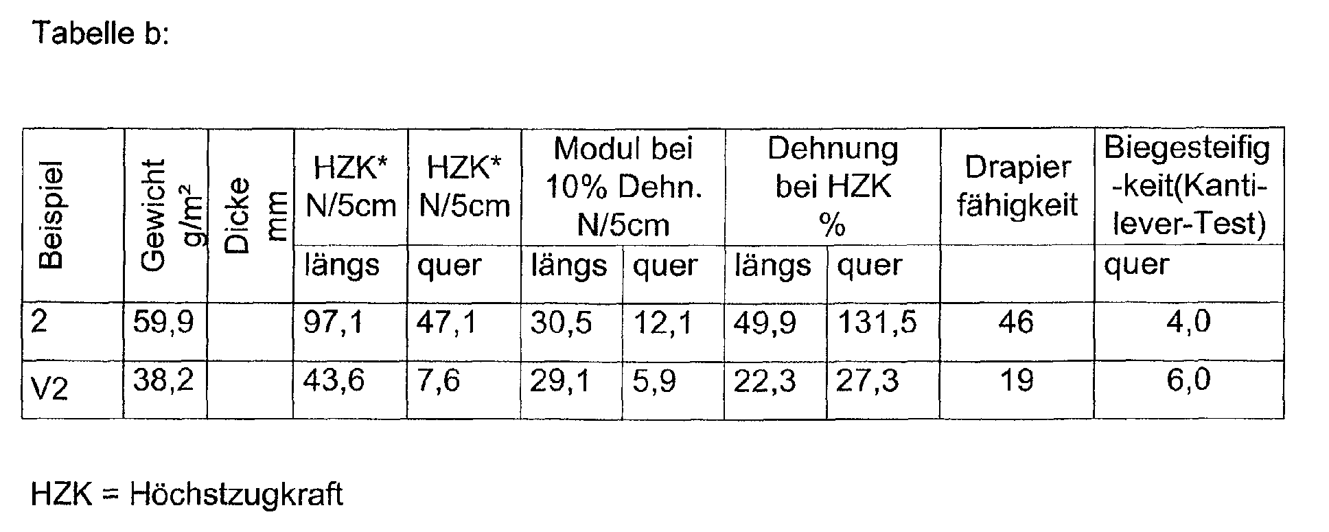
Man sieht aus den Ergebnissen der Tabelle b noch deutlicher als in Tabelle a den Anstieg der HZK quer um das mehr als 6-fache verbunden mit einer extrem starken Steigerung der Dehnung quer auf das ca. 5-fache, was auf die relativ hohe Verdehnbarkeit der gebildeten Folienquerbändchen zurückzuführen ist.One can see from the results of table b even more clearly than in table a the increase in the HZK across by more than 6 times associated with an extreme strong increase in stretching across to about 5 times what on the relative high elasticity of the film cross ribbons formed is attributable.
Mit derselben Anordnung wie in Beispiel 1 und 2 wurde ein 25 g/m2 schwerer Wirrflor aus 100 % Polypropylen-Stapelfasern mit einem Titer von 1,7 und einer Stapelfaserlänge von 40 mm in Maschinenlaufrichtung und ein 8 g/ g/m2 schwerer Längsflor aus 100% Polypropylenfasern mit einem Titer von 1,7 dtex einer Schnittlänge von 40 mm auf Transportbändern abgelegt und zwischen den beiden Floren wieder eine PP-Folie in der im Beispiel 1 beschriebenen Art und Weise positioniert. Die im Beispiel 3 eingesetzte Polypropylen-Folie unterschied sich insbesondere von den beiden in Beispiel 1 und 2 verwendeten Folien dadurch, dass sie nach dem Chill-Roll-Verfahren (d.h. Aufgießen einer Folie aus einer Breitschlitzdüse auf eine Walze) hergestellt worden ist und gezielt extrem stark mit einem Reckverhältnis von 1 : 5 in Maschinenlaufrichtung (über mehrere Reckzonen und Walzen) und quer zur Maschinenlaufrichtung auf das 9-fache der ursprünglichen Breite gereckt worden war (Reckverhältnis quer 1 : 9). Die Stärke dieser extrem stark biaxial gereckten Polypropylen-Folie betrug nur 12 µm. Der Schmelzpunkt der Folie lag im Bereich von 160 bis 166°C und ihre Höchstzugkräfte längs bei 83 N/5cm und quer von 150 N/5cm.With the same arrangement as in Examples 1 and 2, a 25 g / m 2 heavy pile made of 100% polypropylene staple fibers with a titer of 1.7 and a staple fiber length of 40 mm in the machine direction and an 8 g / g / m 2 heavy web were produced from 100% polypropylene fibers with a titer of 1.7 dtex and a cutting length of 40 mm are placed on conveyor belts and a PP film is again positioned between the two webs in the manner described in Example 1. The polypropylene film used in Example 3 differed in particular from the two films used in Examples 1 and 2 in that it was produced by the chill-roll process (ie pouring a film from a slot die onto a roller) and specifically extremely strong with a stretch ratio of 1: 5 in the machine direction (across several stretching zones and rollers) and transversely to the machine direction to 9 times the original width (stretch ratio transversely 1: 9). The thickness of this extremely biaxially stretched polypropylene film was only 12 µm. The melting point of the film was in the range of 160 to 166 ° C and its maximum tensile forces were 83 N / 5 cm lengthways and 150 N / 5 cm crossways.
Die Temperaturen beider Kalanderwalze betrugen 155°C und der Liniendruck im Kalanderpressspalt wiederum 55 N/mm. The temperatures of both calender rolls were 155 ° C and the line pressure 55 N / mm in the calender press nip.
Wie in Beispiel 1 wurde durch Anlegen einer Zugspannung linienförmige Folienstreifen in der Mitte des Verbundstoffes erzielt. In der Ware verblieb nach Entlastung eine Längenkürzung um 2.6 % und eine im Vergleich zu Beispiel 1 deutlich höheren Breitenverlust durch Schrumpf von 15.4%. der starke Breitenverlust zeigt sich in einem starken Mikrokreppeffekt über die breite, d. h. entlang der Folienstreifen. Der Gesamtflächenverlust betrug damit 17,6%As in Example 1, it became linear by applying tensile stress Film strips achieved in the middle of the composite. Remained in the goods Relief of a length reduction of 2.6% and one in comparison to example 1 significantly higher width loss due to shrinkage of 15.4%. the strong Loss of width is shown by a strong micro-crepe effect across the broad, i.e. H. along the film strips. The total area loss was 17.6%
Es wurde in Beispiel 3 ein Verbundstoff geschaffen, der optisch beinahe dem mit Beispiel 1 identisch war, sich jedoch von Beispiel 1 insbesondere durch höhere Querfestigkeiten unterschied und einen etwas härten Griff. Die hohe Steigerung der HZK in Querrichtung gegenüber Beispiel 1 war ausschließlich auf den hohen Reckgrad der PP-Folie quer zur Maschinenlaufrichtung (Reckgrad 1 : 9) zurückzuführen.In example 3, a composite was created that optically almost matched the was identical to Example 1, but differed from Example 1 in particular higher transverse strengths and a somewhat hard grip. The height The increase in the HZK in the transverse direction compared to Example 1 was exclusive the high degree of stretching of the PP film across the machine direction (Degree of stretching 1: 9).
Vergleichsbeispiel zu 3: Es wurde, wie bereits bei der Vergleichbeispielen zu 1 und 2 beschrieben, die Folie weggelassen, d.h. unter den ansonsten in Beispiel 3 beschriebenen Verhältnissen ein 2-schichtiger Vliesstoff mit starker Längsorientierung hergestellt.Comparative example for 3: As in the comparative examples for 1 and 2, the film is omitted, i.e. among the others in example 3 ratios described a 2-layer nonwoven with strong Longitudinal orientation made.
Die Prüfdaten des Beispieles 3 und des Vergleichbeispieles zu 3 sind in Tabelle
c zusammengefasst:

Aus Tabelle c wird sehr klar ersichtlich, wie stark insbesondere die HZK quer durch den erfindungsgemäßen Aufbau und das angewandte Verfahren zur Herstellung desselben angehoben werden kann. Das Längs-/Quer-Verhältnis von 5 / 1 im Vergleichsmuster konnte in Beispiel drei auf 1 / 1,28 völlig verändert werden; d.h. aus einem stark längsorientierten Vliesstoff wurde sogar ein Verbundstoff mit höheren Quer- als Längsfestigkeiten geschaffen.Table c shows very clearly how strong the HZK in particular is by the structure according to the invention and the method used for Production of the same can be raised. The longitudinal / lateral ratio from 5/1 in the comparison sample could completely in example three to 1 / 1.28 to be changed; i.e. a strongly length-oriented nonwoven even became created a composite with higher transverse than longitudinal strengths.
Claims (24)
Applications Claiming Priority (2)
| Application Number | Priority Date | Filing Date | Title |
|---|---|---|---|
| DE10135111 | 2001-07-19 | ||
| DE10135111A DE10135111C2 (en) | 2001-07-19 | 2001-07-19 | Composite, process for its production and its use |
Publications (1)
| Publication Number | Publication Date |
|---|---|
| EP1277868A1 true EP1277868A1 (en) | 2003-01-22 |
Family
ID=7692320
Family Applications (1)
| Application Number | Title | Priority Date | Filing Date |
|---|---|---|---|
| EP02011546A Ceased EP1277868A1 (en) | 2001-07-19 | 2002-05-24 | Composite nonwoven with high perpendicular strength, process of manufacturing and usage |
Country Status (7)
| Country | Link |
|---|---|
| US (1) | US20030059587A1 (en) |
| EP (1) | EP1277868A1 (en) |
| CA (1) | CA2394233A1 (en) |
| DE (1) | DE10135111C2 (en) |
| MX (1) | MXPA02006913A (en) |
| PL (1) | PL354985A1 (en) |
| ZA (1) | ZA200205761B (en) |
Cited By (8)
| Publication number | Priority date | Publication date | Assignee | Title |
|---|---|---|---|---|
| WO2007036338A2 (en) * | 2005-09-27 | 2007-04-05 | Inatec Gmbh | Method and device for applying adhesive threads and points to a substrate, web of material comprising a fleece and a layer composed of adhesive threads, and products made therefrom |
| WO2008028120A1 (en) * | 2006-08-31 | 2008-03-06 | Avery Dennison Corporation | Stretchable laminate |
| WO2009111274A2 (en) * | 2008-02-29 | 2009-09-11 | Avery Dennison Corporation | Elastic laminate |
| EP2269477A1 (en) * | 2009-07-02 | 2011-01-05 | X-Technology Swiss GmbH | Waterproof and water vapour-porous membrane |
| WO2011070116A1 (en) * | 2009-12-09 | 2011-06-16 | Saertex Gmbh & Co. Kg | Semifinished textile product and method for the production thereof |
| US8080198B2 (en) | 2006-10-20 | 2011-12-20 | Avery Dennison Corporation | Elastic diaper component |
| EP3192910A1 (en) * | 2016-01-15 | 2017-07-19 | Reifenhäuser GmbH & Co. KG Maschinenfabrik | Method for manufacturing a laminate and laminate |
| EP3974572A1 (en) * | 2020-09-25 | 2022-03-30 | Reifenhäuser GmbH & Co. KG Maschinenfabrik | Non-woven item and method for producing a non-woven item and |
Families Citing this family (14)
| Publication number | Priority date | Publication date | Assignee | Title |
|---|---|---|---|---|
| DE10319754A1 (en) * | 2003-04-30 | 2004-12-02 | Carl Freudenberg Kg | Elastic composite, process for its preparation and its use |
| DE50301277D1 (en) * | 2003-08-20 | 2006-02-09 | Reifenhaeuser Gmbh & Co Kg | Fiber laminate and method of making a fiber laminate |
| DE102004058140B4 (en) * | 2004-11-25 | 2007-09-20 | Tesa Ag | Hydroactive plaster with three-dimensional tangle coating |
| DE102005048442A1 (en) * | 2005-10-07 | 2007-04-12 | Linotec Development Gmbh | Laminate, useful as a component in building products, medical products or safety clothings, comprises a first- and second fleece from thermoplastic polyolefin material and a prefabricated, stretched lattice |
| JP5342879B2 (en) * | 2006-12-08 | 2013-11-13 | ユニ・チャーム株式会社 | Absorbent articles |
| US20080182048A1 (en) * | 2007-01-25 | 2008-07-31 | William Ouellette | Multizone Web |
| DE202011000582U1 (en) * | 2011-03-15 | 2012-06-21 | Mcairlaid's Vliesstoffe Gmbh & Co. Kg | web |
| CA2779969A1 (en) | 2012-06-18 | 2013-12-18 | Allan R. MANNINEN | In-line shear resistant nonwoven textiles comprised of selectively slit and embossed film |
| USD773195S1 (en) * | 2015-04-09 | 2016-12-06 | The Procter & Gamble Company | Paper product |
| US11220085B2 (en) * | 2017-08-31 | 2022-01-11 | Kimberly-Clark Worldwide, Inc. | Apertured elastic film laminates |
| USD906692S1 (en) * | 2018-09-13 | 2021-01-05 | Fitesa Germany Gmbh | Sheet material |
| USD911042S1 (en) * | 2019-09-13 | 2021-02-23 | Dell Products L.P. | Fabric with ornamentation |
| DE102019133239A1 (en) * | 2019-12-05 | 2021-06-10 | Carl Freudenberg Kg | Articles for mechanical wound cleaning |
| USD1024446S1 (en) * | 2020-02-18 | 2024-04-23 | Design Blue Limited | Protective pad |
Citations (8)
| Publication number | Priority date | Publication date | Assignee | Title |
|---|---|---|---|---|
| GB1331817A (en) * | 1970-01-26 | 1973-09-26 | Johnson & Johnson | Crupled laminated fabrics and methods of making the same |
| FR2581666A1 (en) * | 1985-05-07 | 1986-11-14 | Beghin Say Sa | Nonwoven fabric especially for sterilisable compresses |
| EP0556749A1 (en) * | 1992-02-13 | 1993-08-25 | Japan Absorbent Technology Institute | A sheet elastic complex used in sanitary products, its manufacturing process, and its usages |
| WO1995003171A1 (en) * | 1993-07-23 | 1995-02-02 | Fiberweb North America, Inc. | Composite nonwoven fabrics |
| DE19647459A1 (en) * | 1996-11-16 | 1998-05-20 | Mildenberger & Willing Verpack | Elastic absorbent material for sanitary wear |
| EP0936061A2 (en) * | 1998-02-17 | 1999-08-18 | Firma Carl Freudenberg | Composite material |
| US6238767B1 (en) * | 1997-09-15 | 2001-05-29 | Kimberly-Clark Worldwide, Inc. | Laminate having improved barrier properties |
| US20020033562A1 (en) * | 1999-08-13 | 2002-03-21 | Michael Kauschke | Nonwoven fabric with high CD elongation and method of making same |
Family Cites Families (9)
| Publication number | Priority date | Publication date | Assignee | Title |
|---|---|---|---|---|
| US5244482A (en) * | 1992-03-26 | 1993-09-14 | The University Of Tennessee Research Corporation | Post-treatment of nonwoven webs |
| US6051177A (en) * | 1996-03-11 | 2000-04-18 | Ward; Gregory F. | Thermo-mechanical modification of nonwoven webs |
| DE19709352C2 (en) * | 1997-03-07 | 1999-01-14 | Corovin Gmbh | Plastic film with mineral additives and process for their production |
| US6663611B2 (en) * | 1999-09-28 | 2003-12-16 | Kimberly-Clark Worldwide, Inc. | Breathable diaper with low to moderately breathable inner laminate and more breathable outer cover |
| US6620144B1 (en) * | 1999-11-08 | 2003-09-16 | Mcneil-Ppc, Inc. | Compound napkin |
| DE29921809U1 (en) * | 1999-12-11 | 2001-05-03 | Maksimow Aleander | Fibrous web |
| US6632504B1 (en) * | 2000-03-17 | 2003-10-14 | Bba Nonwovens Simpsonville, Inc. | Multicomponent apertured nonwoven |
| US6537930B1 (en) * | 2000-05-18 | 2003-03-25 | Tredegar Film Products Corporation | Three-dimensional highly elastic film/non-woven composite |
| US7083839B2 (en) * | 2001-12-20 | 2006-08-01 | Kimberly-Clark Worldwide, Inc. | Laminate structures containing activatable materials |
-
2001
- 2001-07-19 DE DE10135111A patent/DE10135111C2/en not_active Expired - Fee Related
-
2002
- 2002-05-24 EP EP02011546A patent/EP1277868A1/en not_active Ceased
- 2002-07-10 PL PL02354985A patent/PL354985A1/en unknown
- 2002-07-15 MX MXPA02006913A patent/MXPA02006913A/en not_active Application Discontinuation
- 2002-07-17 US US10/196,765 patent/US20030059587A1/en not_active Abandoned
- 2002-07-18 ZA ZA200205761A patent/ZA200205761B/en unknown
- 2002-07-19 CA CA002394233A patent/CA2394233A1/en not_active Abandoned
Patent Citations (8)
| Publication number | Priority date | Publication date | Assignee | Title |
|---|---|---|---|---|
| GB1331817A (en) * | 1970-01-26 | 1973-09-26 | Johnson & Johnson | Crupled laminated fabrics and methods of making the same |
| FR2581666A1 (en) * | 1985-05-07 | 1986-11-14 | Beghin Say Sa | Nonwoven fabric especially for sterilisable compresses |
| EP0556749A1 (en) * | 1992-02-13 | 1993-08-25 | Japan Absorbent Technology Institute | A sheet elastic complex used in sanitary products, its manufacturing process, and its usages |
| WO1995003171A1 (en) * | 1993-07-23 | 1995-02-02 | Fiberweb North America, Inc. | Composite nonwoven fabrics |
| DE19647459A1 (en) * | 1996-11-16 | 1998-05-20 | Mildenberger & Willing Verpack | Elastic absorbent material for sanitary wear |
| US6238767B1 (en) * | 1997-09-15 | 2001-05-29 | Kimberly-Clark Worldwide, Inc. | Laminate having improved barrier properties |
| EP0936061A2 (en) * | 1998-02-17 | 1999-08-18 | Firma Carl Freudenberg | Composite material |
| US20020033562A1 (en) * | 1999-08-13 | 2002-03-21 | Michael Kauschke | Nonwoven fabric with high CD elongation and method of making same |
Cited By (14)
| Publication number | Priority date | Publication date | Assignee | Title |
|---|---|---|---|---|
| WO2007036338A2 (en) * | 2005-09-27 | 2007-04-05 | Inatec Gmbh | Method and device for applying adhesive threads and points to a substrate, web of material comprising a fleece and a layer composed of adhesive threads, and products made therefrom |
| WO2007036338A3 (en) * | 2005-09-27 | 2007-08-23 | Inatec Gmbh | Method and device for applying adhesive threads and points to a substrate, web of material comprising a fleece and a layer composed of adhesive threads, and products made therefrom |
| US8323730B2 (en) | 2005-09-27 | 2012-12-04 | Illinois Tools Works, Inc. | Method and device for applying adhesive therads and points to a substrate, web of material comprising a fleece and a layer composed of adhesive threads, and products made therefrom |
| WO2008028120A1 (en) * | 2006-08-31 | 2008-03-06 | Avery Dennison Corporation | Stretchable laminate |
| WO2008028106A2 (en) * | 2006-08-31 | 2008-03-06 | Avery Dennison Corporation | Elastic diaper component |
| WO2008028106A3 (en) * | 2006-08-31 | 2008-08-21 | Avery Dennison Corp | Elastic diaper component |
| US9314991B2 (en) | 2006-08-31 | 2016-04-19 | Avery Dennison Corporation | Elastic laminate |
| US8080198B2 (en) | 2006-10-20 | 2011-12-20 | Avery Dennison Corporation | Elastic diaper component |
| WO2009111274A3 (en) * | 2008-02-29 | 2009-11-26 | Avery Dennison Corporation | Elastic laminate |
| WO2009111274A2 (en) * | 2008-02-29 | 2009-09-11 | Avery Dennison Corporation | Elastic laminate |
| EP2269477A1 (en) * | 2009-07-02 | 2011-01-05 | X-Technology Swiss GmbH | Waterproof and water vapour-porous membrane |
| WO2011070116A1 (en) * | 2009-12-09 | 2011-06-16 | Saertex Gmbh & Co. Kg | Semifinished textile product and method for the production thereof |
| EP3192910A1 (en) * | 2016-01-15 | 2017-07-19 | Reifenhäuser GmbH & Co. KG Maschinenfabrik | Method for manufacturing a laminate and laminate |
| EP3974572A1 (en) * | 2020-09-25 | 2022-03-30 | Reifenhäuser GmbH & Co. KG Maschinenfabrik | Non-woven item and method for producing a non-woven item and |
Also Published As
| Publication number | Publication date |
|---|---|
| CA2394233A1 (en) | 2003-01-19 |
| ZA200205761B (en) | 2004-10-18 |
| US20030059587A1 (en) | 2003-03-27 |
| MXPA02006913A (en) | 2004-12-13 |
| PL354985A1 (en) | 2003-01-27 |
| DE10135111A1 (en) | 2003-02-06 |
| DE10135111C2 (en) | 2003-06-26 |
Similar Documents
| Publication | Publication Date | Title |
|---|---|---|
| DE10135111C2 (en) | Composite, process for its production and its use | |
| DE2356720C2 (en) | Composite nonwoven material | |
| EP1425161B1 (en) | Perforated laminate | |
| DE10151045C2 (en) | Nonwoven composite for mechanical closure systems, process for its production and its use | |
| DE69529768T2 (en) | METHOD AND PRODUCTION FOR HYDRO-Tangling Nonwovens | |
| DE69725512T2 (en) | Bulky nonwoven fabric and process for its production | |
| DE69721773T2 (en) | Laminate structure and method for producing a laminate structure | |
| EP1277865B1 (en) | Non-woven with regular three-dimensional pattern, process for producing the same and applications | |
| DE10319754A1 (en) | Elastic composite, process for its preparation and its use | |
| EP1262587A1 (en) | Multilayer material and manufacturing process | |
| DE3123912A1 (en) | "METHOD FOR PRODUCING A TIED FIBER FABRIC AND TIED FIBER FIBER PRODUCED BY THE METHOD | |
| DE19806530B4 (en) | Laminate and hygiene articles made therefrom, packaging materials and tree membranes | |
| DE2518532B2 (en) | Device for thermal bonding of a fiber fleece in places | |
| EP3192910B1 (en) | Method for manufacturing a laminate and laminate | |
| DE3634139C2 (en) | Multi-layer nonwoven | |
| DE10133772B4 (en) | Three-dimensionally structured fibrous sheet with high liquid absorption and method for its production and its use | |
| EP3334857A1 (en) | Method for producing a structured microfilament nonwoven | |
| DE2536417A1 (en) | LAMINATE MADE FROM CELLULOSE WADDING AND EMBEDDED IN THIS REINFORCEMENT LAYER MADE OF TEXTILE FIBERS, AND THE PROCESS FOR THE PRODUCTION OF THIS | |
| DE69929965T2 (en) | IMPROVEMENTS RELATING TO METHOD FOR THERMAL LAMINATION | |
| EP0966580B1 (en) | Plastic film with mineral additives, method for the production and use thereof | |
| DE3634146C2 (en) | Nonwoven and its manufacture | |
| EP1144187B1 (en) | Multi-layer composite material | |
| EP2758580B1 (en) | Non-woven material with a matrix containing elementary filaments | |
| DE10352958B4 (en) | Use of a highly tear-resistant composite as an entanglement part of a mechanical closure system | |
| DE2503853A1 (en) | PROCESS FOR CONTINUOUS SHRINKAGE OF A WET MANUFACTURED NON-WOVEN WEB AND NON-WOVEN WEB MANUFACTURED BY THE METHOD |
Legal Events
| Date | Code | Title | Description |
|---|---|---|---|
| PUAI | Public reference made under article 153(3) epc to a published international application that has entered the european phase |
Free format text: ORIGINAL CODE: 0009012 |
|
| 17P | Request for examination filed |
Effective date: 20020614 |
|
| AK | Designated contracting states |
Kind code of ref document: A1 Designated state(s): AT BE CH CY DE DK ES FI FR GB GR IE IT LI LU MC NL PT SE TR |
|
| AX | Request for extension of the european patent |
Free format text: AL;LT;LV;MK;RO;SI |
|
| AKX | Designation fees paid |
Designated state(s): AT BE CH CY DE DK ES FI FR GB GR IE IT LI LU MC NL PT SE TR |
|
| STAA | Information on the status of an ep patent application or granted ep patent |
Free format text: STATUS: THE APPLICATION HAS BEEN REFUSED |
|
| 18R | Application refused |
Effective date: 20060426 |