EP1277698A2 - Low pressure drop heat exchange reformer - Google Patents
Low pressure drop heat exchange reformer Download PDFInfo
- Publication number
- EP1277698A2 EP1277698A2 EP02014634A EP02014634A EP1277698A2 EP 1277698 A2 EP1277698 A2 EP 1277698A2 EP 02014634 A EP02014634 A EP 02014634A EP 02014634 A EP02014634 A EP 02014634A EP 1277698 A2 EP1277698 A2 EP 1277698A2
- Authority
- EP
- European Patent Office
- Prior art keywords
- catalyst
- tubes
- tube
- monolithic structures
- structures comprise
- Prior art date
- Legal status (The legal status is an assumption and is not a legal conclusion. Google has not performed a legal analysis and makes no representation as to the accuracy of the status listed.)
- Granted
Links
- 239000003054 catalyst Substances 0.000 claims abstract description 125
- 238000002407 reforming Methods 0.000 claims abstract description 66
- 239000007789 gas Substances 0.000 claims abstract description 59
- 239000004215 Carbon black (E152) Substances 0.000 claims abstract description 32
- 229930195733 hydrocarbon Natural products 0.000 claims abstract description 32
- 150000002430 hydrocarbons Chemical class 0.000 claims abstract description 32
- 239000000203 mixture Substances 0.000 claims abstract description 28
- 238000001193 catalytic steam reforming Methods 0.000 claims abstract description 25
- 238000004519 manufacturing process Methods 0.000 claims abstract description 9
- 238000001816 cooling Methods 0.000 claims abstract description 6
- 238000002156 mixing Methods 0.000 claims abstract description 6
- 239000007800 oxidant agent Substances 0.000 claims abstract description 6
- 230000001590 oxidative effect Effects 0.000 claims abstract description 6
- PXHVJJICTQNCMI-UHFFFAOYSA-N Nickel Chemical compound [Ni] PXHVJJICTQNCMI-UHFFFAOYSA-N 0.000 claims description 39
- 239000000919 ceramic Substances 0.000 claims description 37
- 239000006260 foam Substances 0.000 claims description 31
- 238000012546 transfer Methods 0.000 claims description 24
- 239000012530 fluid Substances 0.000 claims description 22
- 229910052759 nickel Inorganic materials 0.000 claims description 18
- 239000000758 substrate Substances 0.000 claims description 10
- 238000007599 discharging Methods 0.000 claims description 6
- 238000011049 filling Methods 0.000 claims description 5
- 238000000034 method Methods 0.000 abstract description 10
- 230000008569 process Effects 0.000 abstract description 5
- 238000013461 design Methods 0.000 description 18
- 238000006243 chemical reaction Methods 0.000 description 8
- 230000000052 comparative effect Effects 0.000 description 8
- 239000011149 active material Substances 0.000 description 7
- 239000002245 particle Substances 0.000 description 7
- 230000000694 effects Effects 0.000 description 6
- 238000013459 approach Methods 0.000 description 5
- VNWKTOKETHGBQD-UHFFFAOYSA-N methane Chemical compound C VNWKTOKETHGBQD-UHFFFAOYSA-N 0.000 description 5
- 238000005470 impregnation Methods 0.000 description 4
- 238000012856 packing Methods 0.000 description 4
- 238000004513 sizing Methods 0.000 description 4
- 230000003197 catalytic effect Effects 0.000 description 3
- 238000005524 ceramic coating Methods 0.000 description 3
- 239000012700 ceramic precursor Substances 0.000 description 3
- 238000012552 review Methods 0.000 description 3
- PNEYBMLMFCGWSK-UHFFFAOYSA-N Alumina Chemical compound [O-2].[O-2].[O-2].[Al+3].[Al+3] PNEYBMLMFCGWSK-UHFFFAOYSA-N 0.000 description 2
- 238000001833 catalytic reforming Methods 0.000 description 2
- 238000012423 maintenance Methods 0.000 description 2
- 239000008188 pellet Substances 0.000 description 2
- 230000009467 reduction Effects 0.000 description 2
- 239000007787 solid Substances 0.000 description 2
- 229910000990 Ni alloy Inorganic materials 0.000 description 1
- 229910045601 alloy Inorganic materials 0.000 description 1
- 239000000956 alloy Substances 0.000 description 1
- QVGXLLKOCUKJST-UHFFFAOYSA-N atomic oxygen Chemical compound [O] QVGXLLKOCUKJST-UHFFFAOYSA-N 0.000 description 1
- 230000008901 benefit Effects 0.000 description 1
- 238000001354 calcination Methods 0.000 description 1
- 230000005465 channeling Effects 0.000 description 1
- 238000002485 combustion reaction Methods 0.000 description 1
- 230000006835 compression Effects 0.000 description 1
- 238000007906 compression Methods 0.000 description 1
- 238000005520 cutting process Methods 0.000 description 1
- 230000003247 decreasing effect Effects 0.000 description 1
- 238000011161 development Methods 0.000 description 1
- 238000011156 evaluation Methods 0.000 description 1
- 238000011835 investigation Methods 0.000 description 1
- 239000007788 liquid Substances 0.000 description 1
- 238000011068 loading method Methods 0.000 description 1
- 239000000463 material Substances 0.000 description 1
- 238000002844 melting Methods 0.000 description 1
- 230000008018 melting Effects 0.000 description 1
- 238000012986 modification Methods 0.000 description 1
- 230000004048 modification Effects 0.000 description 1
- 239000001301 oxygen Substances 0.000 description 1
- 229910052760 oxygen Inorganic materials 0.000 description 1
- 238000003825 pressing Methods 0.000 description 1
- 238000003908 quality control method Methods 0.000 description 1
- 238000006057 reforming reaction Methods 0.000 description 1
- 238000009420 retrofitting Methods 0.000 description 1
- 238000000629 steam reforming Methods 0.000 description 1
- 238000011144 upstream manufacturing Methods 0.000 description 1
- 239000011800 void material Substances 0.000 description 1
Images


Classifications
-
- B—PERFORMING OPERATIONS; TRANSPORTING
- B01—PHYSICAL OR CHEMICAL PROCESSES OR APPARATUS IN GENERAL
- B01J—CHEMICAL OR PHYSICAL PROCESSES, e.g. CATALYSIS OR COLLOID CHEMISTRY; THEIR RELEVANT APPARATUS
- B01J8/00—Chemical or physical processes in general, conducted in the presence of fluids and solid particles; Apparatus for such processes
- B01J8/02—Chemical or physical processes in general, conducted in the presence of fluids and solid particles; Apparatus for such processes with stationary particles, e.g. in fixed beds
- B01J8/0292—Chemical or physical processes in general, conducted in the presence of fluids and solid particles; Apparatus for such processes with stationary particles, e.g. in fixed beds with stationary packing material in the bed, e.g. bricks, wire rings, baffles
-
- B—PERFORMING OPERATIONS; TRANSPORTING
- B01—PHYSICAL OR CHEMICAL PROCESSES OR APPARATUS IN GENERAL
- B01J—CHEMICAL OR PHYSICAL PROCESSES, e.g. CATALYSIS OR COLLOID CHEMISTRY; THEIR RELEVANT APPARATUS
- B01J8/00—Chemical or physical processes in general, conducted in the presence of fluids and solid particles; Apparatus for such processes
- B01J8/02—Chemical or physical processes in general, conducted in the presence of fluids and solid particles; Apparatus for such processes with stationary particles, e.g. in fixed beds
-
- B—PERFORMING OPERATIONS; TRANSPORTING
- B01—PHYSICAL OR CHEMICAL PROCESSES OR APPARATUS IN GENERAL
- B01J—CHEMICAL OR PHYSICAL PROCESSES, e.g. CATALYSIS OR COLLOID CHEMISTRY; THEIR RELEVANT APPARATUS
- B01J19/00—Chemical, physical or physico-chemical processes in general; Their relevant apparatus
- B01J19/30—Loose or shaped packing elements, e.g. Raschig rings or Berl saddles, for pouring into the apparatus for mass or heat transfer
-
- B—PERFORMING OPERATIONS; TRANSPORTING
- B01—PHYSICAL OR CHEMICAL PROCESSES OR APPARATUS IN GENERAL
- B01J—CHEMICAL OR PHYSICAL PROCESSES, e.g. CATALYSIS OR COLLOID CHEMISTRY; THEIR RELEVANT APPARATUS
- B01J23/00—Catalysts comprising metals or metal oxides or hydroxides, not provided for in group B01J21/00
- B01J23/70—Catalysts comprising metals or metal oxides or hydroxides, not provided for in group B01J21/00 of the iron group metals or copper
- B01J23/74—Iron group metals
- B01J23/755—Nickel
-
- B01J35/50—
-
- B—PERFORMING OPERATIONS; TRANSPORTING
- B01—PHYSICAL OR CHEMICAL PROCESSES OR APPARATUS IN GENERAL
- B01J—CHEMICAL OR PHYSICAL PROCESSES, e.g. CATALYSIS OR COLLOID CHEMISTRY; THEIR RELEVANT APPARATUS
- B01J8/00—Chemical or physical processes in general, conducted in the presence of fluids and solid particles; Apparatus for such processes
- B01J8/008—Details of the reactor or of the particulate material; Processes to increase or to retard the rate of reaction
-
- B—PERFORMING OPERATIONS; TRANSPORTING
- B01—PHYSICAL OR CHEMICAL PROCESSES OR APPARATUS IN GENERAL
- B01J—CHEMICAL OR PHYSICAL PROCESSES, e.g. CATALYSIS OR COLLOID CHEMISTRY; THEIR RELEVANT APPARATUS
- B01J8/00—Chemical or physical processes in general, conducted in the presence of fluids and solid particles; Apparatus for such processes
- B01J8/02—Chemical or physical processes in general, conducted in the presence of fluids and solid particles; Apparatus for such processes with stationary particles, e.g. in fixed beds
- B01J8/06—Chemical or physical processes in general, conducted in the presence of fluids and solid particles; Apparatus for such processes with stationary particles, e.g. in fixed beds in tube reactors; the solid particles being arranged in tubes
- B01J8/067—Heating or cooling the reactor
-
- C—CHEMISTRY; METALLURGY
- C01—INORGANIC CHEMISTRY
- C01B—NON-METALLIC ELEMENTS; COMPOUNDS THEREOF; METALLOIDS OR COMPOUNDS THEREOF NOT COVERED BY SUBCLASS C01C
- C01B3/00—Hydrogen; Gaseous mixtures containing hydrogen; Separation of hydrogen from mixtures containing it; Purification of hydrogen
- C01B3/02—Production of hydrogen or of gaseous mixtures containing a substantial proportion of hydrogen
- C01B3/32—Production of hydrogen or of gaseous mixtures containing a substantial proportion of hydrogen by reaction of gaseous or liquid organic compounds with gasifying agents, e.g. water, carbon dioxide, air
- C01B3/34—Production of hydrogen or of gaseous mixtures containing a substantial proportion of hydrogen by reaction of gaseous or liquid organic compounds with gasifying agents, e.g. water, carbon dioxide, air by reaction of hydrocarbons with gasifying agents
- C01B3/38—Production of hydrogen or of gaseous mixtures containing a substantial proportion of hydrogen by reaction of gaseous or liquid organic compounds with gasifying agents, e.g. water, carbon dioxide, air by reaction of hydrocarbons with gasifying agents using catalysts
- C01B3/382—Multi-step processes
-
- C—CHEMISTRY; METALLURGY
- C01—INORGANIC CHEMISTRY
- C01B—NON-METALLIC ELEMENTS; COMPOUNDS THEREOF; METALLOIDS OR COMPOUNDS THEREOF NOT COVERED BY SUBCLASS C01C
- C01B3/00—Hydrogen; Gaseous mixtures containing hydrogen; Separation of hydrogen from mixtures containing it; Purification of hydrogen
- C01B3/02—Production of hydrogen or of gaseous mixtures containing a substantial proportion of hydrogen
- C01B3/32—Production of hydrogen or of gaseous mixtures containing a substantial proportion of hydrogen by reaction of gaseous or liquid organic compounds with gasifying agents, e.g. water, carbon dioxide, air
- C01B3/34—Production of hydrogen or of gaseous mixtures containing a substantial proportion of hydrogen by reaction of gaseous or liquid organic compounds with gasifying agents, e.g. water, carbon dioxide, air by reaction of hydrocarbons with gasifying agents
- C01B3/38—Production of hydrogen or of gaseous mixtures containing a substantial proportion of hydrogen by reaction of gaseous or liquid organic compounds with gasifying agents, e.g. water, carbon dioxide, air by reaction of hydrocarbons with gasifying agents using catalysts
- C01B3/384—Production of hydrogen or of gaseous mixtures containing a substantial proportion of hydrogen by reaction of gaseous or liquid organic compounds with gasifying agents, e.g. water, carbon dioxide, air by reaction of hydrocarbons with gasifying agents using catalysts the catalyst being continuously externally heated
-
- B—PERFORMING OPERATIONS; TRANSPORTING
- B01—PHYSICAL OR CHEMICAL PROCESSES OR APPARATUS IN GENERAL
- B01J—CHEMICAL OR PHYSICAL PROCESSES, e.g. CATALYSIS OR COLLOID CHEMISTRY; THEIR RELEVANT APPARATUS
- B01J2208/00—Processes carried out in the presence of solid particles; Reactors therefor
- B01J2208/00008—Controlling the process
- B01J2208/00017—Controlling the temperature
- B01J2208/00106—Controlling the temperature by indirect heat exchange
- B01J2208/00168—Controlling the temperature by indirect heat exchange with heat exchange elements outside the bed of solid particles
- B01J2208/00212—Plates; Jackets; Cylinders
- B01J2208/00221—Plates; Jackets; Cylinders comprising baffles for guiding the flow of the heat exchange medium
-
- B—PERFORMING OPERATIONS; TRANSPORTING
- B01—PHYSICAL OR CHEMICAL PROCESSES OR APPARATUS IN GENERAL
- B01J—CHEMICAL OR PHYSICAL PROCESSES, e.g. CATALYSIS OR COLLOID CHEMISTRY; THEIR RELEVANT APPARATUS
- B01J2208/00—Processes carried out in the presence of solid particles; Reactors therefor
- B01J2208/00008—Controlling the process
- B01J2208/00017—Controlling the temperature
- B01J2208/00106—Controlling the temperature by indirect heat exchange
- B01J2208/00309—Controlling the temperature by indirect heat exchange with two or more reactions in heat exchange with each other, such as an endothermic reaction in heat exchange with an exothermic reaction
-
- B—PERFORMING OPERATIONS; TRANSPORTING
- B01—PHYSICAL OR CHEMICAL PROCESSES OR APPARATUS IN GENERAL
- B01J—CHEMICAL OR PHYSICAL PROCESSES, e.g. CATALYSIS OR COLLOID CHEMISTRY; THEIR RELEVANT APPARATUS
- B01J2208/00—Processes carried out in the presence of solid particles; Reactors therefor
- B01J2208/00008—Controlling the process
- B01J2208/00017—Controlling the temperature
- B01J2208/00477—Controlling the temperature by thermal insulation means
- B01J2208/00495—Controlling the temperature by thermal insulation means using insulating materials or refractories
-
- B—PERFORMING OPERATIONS; TRANSPORTING
- B01—PHYSICAL OR CHEMICAL PROCESSES OR APPARATUS IN GENERAL
- B01J—CHEMICAL OR PHYSICAL PROCESSES, e.g. CATALYSIS OR COLLOID CHEMISTRY; THEIR RELEVANT APPARATUS
- B01J2208/00—Processes carried out in the presence of solid particles; Reactors therefor
- B01J2208/00008—Controlling the process
- B01J2208/00017—Controlling the temperature
- B01J2208/0053—Controlling multiple zones along the direction of flow, e.g. pre-heating and after-cooling
-
- B—PERFORMING OPERATIONS; TRANSPORTING
- B01—PHYSICAL OR CHEMICAL PROCESSES OR APPARATUS IN GENERAL
- B01J—CHEMICAL OR PHYSICAL PROCESSES, e.g. CATALYSIS OR COLLOID CHEMISTRY; THEIR RELEVANT APPARATUS
- B01J2219/00—Chemical, physical or physico-chemical processes in general; Their relevant apparatus
- B01J2219/30—Details relating to random packing elements
- B01J2219/302—Basic shape of the elements
- B01J2219/30223—Cylinder
-
- B—PERFORMING OPERATIONS; TRANSPORTING
- B01—PHYSICAL OR CHEMICAL PROCESSES OR APPARATUS IN GENERAL
- B01J—CHEMICAL OR PHYSICAL PROCESSES, e.g. CATALYSIS OR COLLOID CHEMISTRY; THEIR RELEVANT APPARATUS
- B01J2219/00—Chemical, physical or physico-chemical processes in general; Their relevant apparatus
- B01J2219/30—Details relating to random packing elements
- B01J2219/302—Basic shape of the elements
- B01J2219/30242—Star
-
- B—PERFORMING OPERATIONS; TRANSPORTING
- B01—PHYSICAL OR CHEMICAL PROCESSES OR APPARATUS IN GENERAL
- B01J—CHEMICAL OR PHYSICAL PROCESSES, e.g. CATALYSIS OR COLLOID CHEMISTRY; THEIR RELEVANT APPARATUS
- B01J2219/00—Chemical, physical or physico-chemical processes in general; Their relevant apparatus
- B01J2219/32—Details relating to packing elements in the form of grids or built-up elements for forming a unit of module inside the apparatus for mass or heat transfer
- B01J2219/322—Basic shape of the elements
- B01J2219/32296—Honeycombs
-
- C—CHEMISTRY; METALLURGY
- C01—INORGANIC CHEMISTRY
- C01B—NON-METALLIC ELEMENTS; COMPOUNDS THEREOF; METALLOIDS OR COMPOUNDS THEREOF NOT COVERED BY SUBCLASS C01C
- C01B2203/00—Integrated processes for the production of hydrogen or synthesis gas
- C01B2203/08—Methods of heating or cooling
- C01B2203/0805—Methods of heating the process for making hydrogen or synthesis gas
- C01B2203/0838—Methods of heating the process for making hydrogen or synthesis gas by heat exchange with exothermic reactions, other than by combustion of fuel
- C01B2203/0844—Methods of heating the process for making hydrogen or synthesis gas by heat exchange with exothermic reactions, other than by combustion of fuel the non-combustive exothermic reaction being another reforming reaction as defined in groups C01B2203/02 - C01B2203/0294
-
- C—CHEMISTRY; METALLURGY
- C01—INORGANIC CHEMISTRY
- C01B—NON-METALLIC ELEMENTS; COMPOUNDS THEREOF; METALLOIDS OR COMPOUNDS THEREOF NOT COVERED BY SUBCLASS C01C
- C01B2203/00—Integrated processes for the production of hydrogen or synthesis gas
- C01B2203/14—Details of the flowsheet
- C01B2203/141—At least two reforming, decomposition or partial oxidation steps in parallel
-
- C—CHEMISTRY; METALLURGY
- C01—INORGANIC CHEMISTRY
- C01B—NON-METALLIC ELEMENTS; COMPOUNDS THEREOF; METALLOIDS OR COMPOUNDS THEREOF NOT COVERED BY SUBCLASS C01C
- C01B2203/00—Integrated processes for the production of hydrogen or synthesis gas
- C01B2203/14—Details of the flowsheet
- C01B2203/142—At least two reforming, decomposition or partial oxidation steps in series
-
- C—CHEMISTRY; METALLURGY
- C01—INORGANIC CHEMISTRY
- C01B—NON-METALLIC ELEMENTS; COMPOUNDS THEREOF; METALLOIDS OR COMPOUNDS THEREOF NOT COVERED BY SUBCLASS C01C
- C01B2203/00—Integrated processes for the production of hydrogen or synthesis gas
- C01B2203/80—Aspect of integrated processes for the production of hydrogen or synthesis gas not covered by groups C01B2203/02 - C01B2203/1695
- C01B2203/82—Several process steps of C01B2203/02 - C01B2203/08 integrated into a single apparatus
-
- Y—GENERAL TAGGING OF NEW TECHNOLOGICAL DEVELOPMENTS; GENERAL TAGGING OF CROSS-SECTIONAL TECHNOLOGIES SPANNING OVER SEVERAL SECTIONS OF THE IPC; TECHNICAL SUBJECTS COVERED BY FORMER USPC CROSS-REFERENCE ART COLLECTIONS [XRACs] AND DIGESTS
- Y02—TECHNOLOGIES OR APPLICATIONS FOR MITIGATION OR ADAPTATION AGAINST CLIMATE CHANGE
- Y02P—CLIMATE CHANGE MITIGATION TECHNOLOGIES IN THE PRODUCTION OR PROCESSING OF GOODS
- Y02P20/00—Technologies relating to chemical industry
- Y02P20/50—Improvements relating to the production of bulk chemicals
- Y02P20/52—Improvements relating to the production of bulk chemicals using catalysts, e.g. selective catalysts
Definitions
- This invention relates to reforming exchangers for syngas production, and more particularly to reforming exchangers with catalyst tubes having a relatively low ratio of inside tube diameter to catalyst particle size.
- a feed comprising a mixture of steam and hydrocarbon is passed through catalyst-filled tubes.
- the outlet ends of the tubes discharge the endothermically reformed gas near the shell side inlet where it mixes with the hot gas from the autothermal reformer.
- the hot gas mixture is then passed countercurrently across the tubes in indirect heat exchange to supply the heat necessary for the endothermic reforming reaction to occur.
- Reforming exchangers are in use commercially and are available, for example, from Kellogg Brown & Root, Inc. under the trade designation KRES.
- KRES Kellogg Brown & Root, Inc.
- Various improvements to the reforming exchanger design have been made, as disclosed in, for example, U.S. Patent 5,362,454 to Cizmar et al., which is hereby incorporated by reference herein in its entirety.
- the present invention addresses improvements to the basic reforming exchanger design.
- the primary design consideration is to minimize the capital cost of the equipment, which is complicated because expensive alloys must be used to construct the tube bundle and tube sheets for the relatively high operating temperatures and pressures.
- Another design consideration is to maximize the capacity of the reforming exchanger within the practical limits of fabrication capabilities. It is also desirable to minimize the size and weight of the reforming exchanger to facilitate maintenance operations that require removal of the tube bundle.
- the present applicants discovered that by carefully packing the tubes with the catalyst particles, the conventional design relationship between the catalyst diameter, D p , and the tube inside diameter, D t , is not applicable, and that a D t /D p ratio of preferably less than 4, and more preferably 3 or less, is employed to reduce the pressure drop in smaller inside diameter (ID) tubes. Quite surprisingly, the present applicants also discovered that the use of smaller ID tubes with a smaller D t /D p ratio results in higher heat transfer coefficients and greater efficiency than tubes designed with a conventional D t /D p ratio.
- the present invention thus provides a solution to the dilemma in the prior art reforming exchanger designs.
- the present invention is the discovery of a tube design in a syngas reforming exchanger employing a catalyst structure and/or arrangement that allows the use of relatively long and/or relatively small-ID tubes.
- the catalyst-packed tubes can have a lower D t /D p ratio than in the prior art reforming exchangers. This allows the capacity of the reforming exchanger to be increased for a given size. Alternatively or additionally, the size and cost of the reforming exchanger for a given syngas production capacity can be significantly reduced.
- the invention provides a syngas production process comprising: (1) passing a first portion of a hydrocarbon feed mixed with steam and oxidant through an autothermal catalytic steam reforming zone to form a first reformed gas of reduced hydrocarbon content; (2) passing a second portion of the hydrocarbon feed mixed with steam through an endothermic catalytic steam reforming zone to form a second reformed gas of reduced hydrocarbon content; (3) mixing the first and second reformed gases and passing the resulting gas mixture through a heat exchange zone for cooling the gas mixture and supplying heat to the endothermic catalytic steam reforming zone; (4) wherein the endothermic catalytic steam reforming zone and the heat exchange zone are respectively disposed tube side and shell side within a shell-and-tube reforming exchanger comprising a plurality of tubes packed with catalyst-bearing monolithic structures, wherein D t /D p is not more than 4, wherein D t is the inside diameter of the tubes and D p is a maximum edge dimension of the catalyst structures; and (5) recovering
- the invention provides apparatus for reforming a hydrocarbon to produce syngas.
- the apparatus includes means for passing a first portion of a hydrocarbon feed mixed with steam and oxidant through an autothermal catalytic steam reforming zone to form a first reformed gas of reduced hydrocarbon content.
- Means are provided for passing a second portion of the hydrocarbon feed mixed with steam through an endothermic catalytic steam reforming zone to form a second reformed gas of reduced hydrocarbon content.
- Means are also provided for mixing the first and second reformed gases and passing the resulting gas mixture through a heat exchange zone for cooling the gas mixture and supplying heat to the endothermic catalytic steam reforming zone.
- the endothermic catalytic steam reforming zone and the heat exchange zone are respectively disposed tube side and shell side within a shell-and-tube reforming exchanger comprising a plurality of tubes packed with catalyst-bearing monolithic structures.
- the tubes have an inside diameter that is not more than 4 times a maximum edge dimension of the catalyst structures.
- Means are further provided for recovering syngas comprising the cooled gas mixture.
- the invention provides a syngas reforming exchanger.
- the exchanger has a tube side fluid inlet, a shell side fluid inlet and outlet, and an elongated shell having relatively high and low temperature ends.
- the shell side fluid inlet is adjacent to the high temperature end for receiving a hot gas feed.
- the tube side fluid inlet is adjacent to the low temperature end for receiving a feed mixture of hydrocarbon and steam.
- the shell side fluid outlet is fluidly isolated from the tube side fluid inlet by a tube sheet that is adjacent to the low temperature end for discharging cooled gas from the reforming exchanger.
- a tube bundle is made up of a plurality of tubes and one or more longitudinally spaced transverse baffle plates.
- the tubes have an inlet end secured to the tube sheet for receiving the feed mixture and an outlet end that is adjacent to the shell side fluid inlet for discharging reformed gas into the hot gas feed.
- Catalyst-bearing monolithic structures are disposed within the tubes for converting the gas feed mixture to reformed gas.
- the tubes have an inside diameter that is not more than 4 times a maximum edge dimension of the catalyst structures.
- the tubes preferably have an L t /D t ratio of at least 300, wherein L t is the length of the catalyst packing in the tubes.
- the combination of the tube ID and the catalyst-bearing monolithic structures preferably results in a higher heat transfer rate for the same given pressure drop, i.e. wherein an overall heat transfer rate is at least 5 percent greater for a given pressure drop than Raschig rings measuring 0.31-in. long by 0.31-in. outside diameter by 0.125-in. inside diameter in tubes having an inside diameter of 2-in.
- the catalyst-bearing monolithic structures in one embodiment, comprise a twisted tape insert.
- the twisted tape insert is preferably made of nickel or a nickel alloy, and can have a wash-coated surface impregnated with a nickel-containing catalyst.
- the twisted tape insert can have a length that is coextensive with the catalyst-packed length of the tubes and an OD that is about equal to the tube ID, such that D t /D p is substantially less than 1, taking the length of the twisted tape insert as the longest edge dimension for D p as defined above.
- the catalyst-bearing monolithic structures comprise a central longitudinal runner and a plurality of bristles extending transversely therefrom.
- the bristles can be wash-coated and impregnated with a nickel-containing catalyst.
- the runner can have a length that is coextensive with the catalyst-packed length of the tubes and an OD that is about equal to the tube ID, such that D t /D p is substantially less than 1, again taking the length of the runner as the longest edge dimension for D p as defined above.
- the catalyst-bearing monolithic structures comprise ceramic foam.
- the ceramic foam can be made by filling voids in an organic sponge substrate with a fluidized ceramic precursor and burning the substrate away to form the ceramic foam.
- the ceramic foam can be impregnated with nickel or another catalytically active material, and is preferably made in sheets, plugs are cut from the sheets having a diameter less than a thickness, and a plurality of the plugs are stacked end-to-end in each tube.
- the ceramic foam plugs preferably have a length or height that is about equal to or greater than the ID of the tubes and an OD that is about equal to the tube ID, such that D t /D p is approximately 1.
- the catalyst-bearing monolithic structures comprise finned, hollow cylinders, also called ribbed rings.
- the ribbed rings preferably have a longitudinal bore formed along a central axis.
- the depth of channels between the fins, i.e. the radial height of the fins, is preferably from 0.1 to 0.3 times the outside diameter (OD) of the structures, measuring to an outer diameter of the fins.
- the ribbed rings can have a length that is roughly 1/3 to 1/4 the tube ID, such that D t /D p is from about 3 to about 4.
- the reforming exchanger 100 has a tube side fluid inlet 102 , shell side fluid inlet 104 , and shell side fluid outlet 106 in an elongated shell 108 having respective relatively high and low temperature ends 110 and 112 , respectively.
- the shell side fluid inlet 104 is adjacent to the high temperature end 110 for receiving a hot gas feed.
- the tube side fluid inlet 102 is adjacent to the low temperature end 112 for receiving a feed mixture of hydrocarbon and steam.
- the shell side fluid outlet 106 is fluidly isolated from the tube side fluid inlet 102 by tube sheet 114 that is adjacent to the low temperature end 112 for discharging cooled gas from the reforming exchanger 100 .
- a tube bundle 116 is made up of a plurality of tubes 118 and one or more longitudinally spaced transverse baffle plates 120 .
- the tubes 118 have an inlet end 122 secured to the tube sheet 114 for receiving the gas mixture, and an outlet end 124 that is adjacent to the shell side fluid inlet 104 for discharging reformed gas into the hot gas feed.
- Low pressure drop ( ⁇ P) catalyst-bearing monolithic structures are disposed within the tubes for converting the gas feed mixture to reformed gas.
- the tubes 118 preferably have a ratio of L t /D t of at least 300, more preferably at least 450 - 500.
- the diameter D t refers to the inside diameter of the tubes 118 in the case of right circular cylindrical tubes, or to the equivalent hydraulic diameter in the case of non-circular tubes.
- the length L t refers to the catalyst-filled or -packed length. Higher L t /D t ratios are preferred in the present invention because the heat transfer coefficients are generally higher than with a lower L t /D t ratio, and the resulting equipment cost is lower.
- a longer, smaller-ID catalyst tube 118 generally results in more tubes 118 in the tube bundle 116 , but the tube bundle 116 has a smaller diameter for a given conversion capacity, allowing the use of a shell 108 that has a smaller diameter.
- the reduction of the diameter of the shell 108 and tube bundle 116 results in more capital cost savings than result from any increase in the length thereof, and thus the reforming exchanger 100 of the present invention can be much cheaper to fabricate than a prior art reforming exchanger of equivalent capacity. This result is particularly advantageous in the design of a new reforming exchanger 100 .
- the conversion capacity of the reforming exchanger 100 is substantially increased. This latter result is particularly advantageous in the retrofitting of existing reforming exchangers by replacing the existing tube bundle with a tube bundle 116 that has relatively more smaller-ID tubes 118 so that the retrofitted reforming exchanger 100 has a higher capacity than the original reforming exchanger.
- the ratio of the tube inside diameter (ID), D t , to the largest edge dimension of the catalyst structure (D p ) can be relatively small compared to the same ratio in conventional reforming exchangers.
- ID tube inside diameter
- D t the largest edge dimension of the catalyst structure
- the minimum tube ID was about 2 inches.
- the same Raschig ring catalyst can be used in approximately 1.25-in. or even 1-in. ID tubes with an equivalent or slightly higher ratio of heat transfer to pressure drop.
- the D t /D p ratio is preferably not more than 4, and more preferably about 3 or less.
- a low ⁇ P catalyst structure is defined herein as any suitable catalyst structure that results in a higher rate of heat transfer per unit of tube side pressure drop than in 2-in.
- ID reforming exchanger tubes filled with catalyst-supporting Raschig rings measuring 0.31-in. OD by 0.125-in. ID by 0.31-in. long under similar operating conditions and conversions.
- low ⁇ P monolithic catalyst support structures are contemplated as being useful in the present invention. While the low ⁇ P is the most important property in the present invention, the exemplary catalysts are also typically found to have a relatively high void fraction and present a tortuous flow path to the tube side fluid. Catalyst activity can be relatively low to moderate without significant reduction in conversion rates, although there is no general detriment to using a high activity catalyst aside from the typically higher cost involved.
- the catalyst support 200 is a ribbed ring catalyst structure comprising an overall cylindrical shape with a central longitudinal bore 202 and exterior ribs 204 running parallel to a longitudinal axis.
- the depth of the V-shaped channel 206 between the ribs is preferably from 0.1 to 0.3 times the OD of the support 200.
- Supports 200 measuring 2.362-in. (6 mm) OD by 0.787-in. (2 mm) ID by 2.362-in. (6 mm) long with a fin 204 height of 0.787-in. (2 mm) comprise one example of a suitably dimensioned support 200 for use in nominal 1-inch or 1.5-inch tubes.
- the ribbed ring supports 200 can be made by pressing a ceramic precursor into molds with a pin to make the central bore 202 , followed by calcining the material at elevated temperatures, e.g. 2500°F, to form a ribbed ring support made of an ⁇ -alumina, for example, and impregnating the ⁇ -alumina with nickel or another suitable catalytically active material.
- Ribbed ring catalyst is commercially available, for example, from Süd-Chemie Inc. of Louisville, Kentucky. Because of the relatively large size of the ribbed ring catalyst compared to the tube 118 ID, the catalyst should preferably be loaded into the tubes 118 using a dense loading method such as is accomplished with the equipment and methodology described in U.S. Patents 6,132,157, 5,897,282, and 5,890,868, which are hereby incorporated herein by reference, in order to minimize any packing or bridging problems.
- the catalyst insert 300 is in the form of a twisted tape having an OD about the same as the ID of the tube 118 in which it is used.
- the OD of the insert 300 is slightly less than the ID of the tube 118 to facilitate placement of the tape insert 300 .
- the length of the insert 300 can be essentially the same length as the tube with one insert 300 in each tube 118 , or multiple inserts 300 can be placed end-to-end in each tube 118 .
- each insert 300 preferably has a length which is at least as great as the diameter in order to keep the inserts 300 longitudinally aligned in the tube 118 .
- the insert 300 can be made of a catalytically active material such as nickel, or it can be coated with a catalytically active material.
- the insert 300 can be wash coated with a ceramic as described in U.S. Patents 5,980,843 to Silversand or 5,935,889 to Murrell et al., both of which are hereby incorporated herein by reference in their entireties, and the ceramic coating impregnated with a nickel catalyst by conventional ceramic impregnation techniques.
- Catalytically inactive forms of such inserts 300 are commercially available for increasing the tube side heat transfer coefficients in a shell-and-tube heat exchanger from, for example, the Brown Fintube Company of Houston, Texas.
- the catalyst insert 400 is in the form of a brush comprising a central runner 402 and a plurality of bristles or filaments 404 extending transversely therefrom.
- the brush insert 400 has an OD about the same as the ID of the tube 118 in which it is used.
- the length of the insert 400 can be essentially the same length as the tube 118 with one insert 400 in each tube 118 , or multiple inserts 400 can be placed end-to-end in each tube 118 , optionally with some overlap.
- each insert 400 should have a length which is at least several times as great as the diameter in order to keep the inserts 400 longitudinally aligned in the tube 118 .
- the insert 400 can be made of a catalytically active material such as nickel, or it can be coated with a catalytically active material.
- the insert 400 can be wash coated with a ceramic as described above, and the ceramic coating impregnated with a nickel catalyst by conventional ceramic impregnation techniques.
- Catalytically inactive forms of such inserts 400 are commercially available for increasing the tube side heat transfer coefficients in a shell-and-tube heat exchanger under, for example, the trade designation HITRAN.
- the catalyst insert 500 is in the form of a ceramic foam.
- the ceramic foam insert 500 is preferably made by filling voids in an organic sponge substrate with a fluidized ceramic precursor and burning the substrate away to form the ceramic foam.
- the ceramic foam can be impregnated with nickel or another catalytically active material using conventional nickel impregnation techniques.
- the ceramic foam insert 500 is preferably made in sheets, plugs 502 are cut from the sheets having a diameter less than a thickness, and a plurality of the plugs 502 are stacked end-to-end in each tube 118 . If necessary, the sheet can be filled with liquid wax, which is solidified to facilitate the cutting of the plugs 502 , and then the wax is removed by melting it.
- the plug 502 has an OD about the same as the ID of the tube 118 in which it is used.
- the length of each plug 502 should be at least as great as the ID of the tube 118 to help keep the plug 502 aligned inside the tube 118 .
- the plugs 502 are placed end-to-end in each tube 118 as illustrated in Fig. 7.
- tube side heat transfer coefficients, flow rates and pressure drops are based on a tube side inlet gas having the composition in Table 1:
- the catalyst was of a normal size currently used in reforming exchangers available from Kellogg Brown & Root, Inc. under the trade designation KRES (Raschig rings 0.31-in. OD by 0.125-in. ID by 0.31-in. long), a smaller catalyst size (Raschig rings 0.25-in. OD by 0.10-in. ID by 0.25-in. long), a smallest catalyst size (Raschig rings 0.185-in. OD by 0.07-in. ID by 0.185-in. long), a twisted tape insert such as a Turbulator available from Brown Fintube but made of nickel 201 (99.6% nickel), and a ceramic foam insert impregnated with nickel.
- KRES Raschig rings 0.31-in. OD by 0.125-in. ID by 0.31-in. long
- a smaller catalyst size Raschig rings 0.25-in. OD by 0.10-in. ID by 0.25-in. long
- a smallest catalyst size Raschig rings 0.185-in. OD
- Example 2 Catalyst Normal (0.31 x0.125 x0.31) Smaller (0.25 x0.10 x0.25) Smallest (0.185 x0.07 x0.185) Solid Pellets (0.185 x0.185) Twisted tape Ceramic foam Refractory ID (in.) 103 114 110 120 48 88 Tube length (ft) 44 44 27 24 60 41 Tube OD (in.) 2 2.5 1.5 1.5 0.75 1.15 Relative no.
- Example 1 is based on the twisted insert measuring 0.625-in. wide by 0.035-in. thick and twisted to 4 revolutions per foot. Performance sizing assumed the same targeted methane slip (2.5%) and the same activity factors as with conventional catalysts. Nickel impregnation of a ceramic coating on the twisted tape insert can improve catalytic activity.
- Example 3 Catalyst 0.31 in. x 0.125 in. x 0.31 in. Raschig rings 0.31 in. x 0.125 in. x 0.31 in. ribbed rings Refractory ID (in.) 55 55 Tube length (ft) 25 25 Tube ID (in.) 2.00 2.00 Tube OD (in.) 2.25 2.25 Relative no.
- Example 3 demonstrate that the performance of the ribbed ring catalyst is generally equivalent to Raschig rings of the same size, except that the tube side pressure drop is substantially lower.
- the cost of the ribbed ring reforming exchanger with a correspondingly reduced number of relatively longer tubes would be much less since exchanger overall length is generally less expensive than exchanger diameter.
- Tubes of various sizes were packed with catalyst shapes comprising Raschig rings, ribbed rings and ceramic foam plugs in a laboratory tube evaluation apparatus. Air was passed through the packed tubes at Reynold's numbers similar to those seen in commercial reforming reactor tubes. The tubes were externally heated to provide tube wall temperatures within a range expected in commercial reforming reactor tubes. Heat transfer coefficients (Btu/hr-ft 2 -°F) for the inside surface of the tubes were determined and pressure drop (psi/ft) was measured. The data were used to compare the ratio of heat transfer to pressure drop relative to a 1.94-in. ID tube with Raschig ring catalyst supports. The ratio was determined for Raschig rings and ribbed rings in 1.94-in. ID and 1.38-in.
- Syngas production process and reforming exchanger involves passing a first portion of hydrocarbon feed mixed with steam and oxidant through an autothermal catalytic steam reforming zone to form a first reformed gas of reduced hydrocarbon content, passing a second portion of the hydrocarbon feed mixed with steam through an endothermic catalytic steam reforming zone to form a second reformed gas of reduced hydrocarbon content, and mixing the first and second reformed gases and passing the resulting gas mixture through a heat exchange zone for cooling the gas mixture and thereby supplying heat to the endothermic catalytic steam reforming zone.
- the endothermic catalytic steam reforming zone and the heat exchange zone are respectively disposed tube side and shell side within a shell-and-tube reforming exchanger.
- the reforming exchanger comprises a plurality of tubes packed with low pressure drop catalyst-bearing monolithic structures wherein an inside diameter of the tubes is less than 4 times a maximum edge dimension of the catalyst structures.
Abstract
Description
- This invention relates to reforming exchangers for syngas production, and more particularly to reforming exchangers with catalyst tubes having a relatively low ratio of inside tube diameter to catalyst particle size.
- Steam reforming of a hydrocarbon to manufacture syngas is a very well known process. One popular technique is to use an autothermal reformer in conjunction with a reforming exchanger, as described in U.S. Patent 5,011,625 to Le Blanc, which is hereby incorporated by reference herein in its entirety. Briefly, the hydrocarbon and an oxygen source are supplied to the autothermal reformer. The combustion reaction is exothermic and supplies the heat needed for the catalytic reforming reaction that occurs in the autothermal reformer, which is endothermic, to produce a relatively hot reformed gas. The hot gas from the autothermal reformer is then used as a heat source in the reforming exchanger, which is operated as an endothermic catalytic steam reforming zone. In the reforming exchanger, a feed comprising a mixture of steam and hydrocarbon is passed through catalyst-filled tubes. The outlet ends of the tubes discharge the endothermically reformed gas near the shell side inlet where it mixes with the hot gas from the autothermal reformer. The hot gas mixture is then passed countercurrently across the tubes in indirect heat exchange to supply the heat necessary for the endothermic reforming reaction to occur.
- Reforming exchangers are in use commercially and are available, for example, from Kellogg Brown & Root, Inc. under the trade designation KRES. Various improvements to the reforming exchanger design have been made, as disclosed in, for example, U.S. Patent 5,362,454 to Cizmar et al., which is hereby incorporated by reference herein in its entirety.
- The present invention addresses improvements to the basic reforming exchanger design. The primary design consideration is to minimize the capital cost of the equipment, which is complicated because expensive alloys must be used to construct the tube bundle and tube sheets for the relatively high operating temperatures and pressures. Another design consideration is to maximize the capacity of the reforming exchanger within the practical limits of fabrication capabilities. It is also desirable to minimize the size and weight of the reforming exchanger to facilitate maintenance operations that require removal of the tube bundle.
- Our approach to reducing the capital cost and increasing the capacity of the reforming exchanger is to increase the heat transfer rate by increasing the surface area available for heat transfer. Increasing the length of the conventional catalyst-filled tubes in the existing reforming exchanger design, however, was not practical because the tube side pressure drop (ΔP) would increase beyond that permitted without unduly complicating the tube sheet and tube sheet support designs, as well as increasing upstream operating pressures and compression costs. Furthermore, longer tubes would complicate the maintenance operations involving removal of the tube bundle.
- The other approach to increasing the heat transfer area is to reduce the diameter of the catalyst-filled tubes. However, it was a commonly held belief among the reforming reactor designers that the inside diameter of the heat transfer tubes had to be a minimum of 5 times the diameter or other largest edge dimension of the catalyst particles, supposedly because of packing, bridging, flow channeling, and other potential problems. For example, James T. Richardson, Principles of Catalyst Development, Plenum Press, New York, New York, p. 8 (1986) (citing E.G. Christoffel, "Laboratory Reactors and Heterogeneous Catalytic Processes," Catal. Rev. - Sci. Eng., vol. 24, p. 159 (1982)), reports that the reactor to particle diameter ratio should be from five to ten, with the reactor length at least 50-100 times the particle diameter, to ensure that the flow is turbulent, uniform, and approximately plug flow.
- To observe these design criteria would mean that reducing the tube diameter and increasing the number of tubes, as a means of increasing the available surface area, would require using a smaller catalyst structure. For example, in tubes having a 2-in. inside diameter (ID), the longitudinally bored, cylindrical catalyst shapes, also known as Raschig rings, prevalent in reforming exchangers used in the art would typically measure 0.315-in. outside diameter (OD) by 0.125-in. ID by 0.31-in. long. When small-ID tubes were specified, it was thought that the size of the catalyst particles had to be correspondingly reduced to adhere to the traditional equation Dt/Dp > 5, wherein Dt is the inside diameter of the tubes in the reforming exchanger and Dp is the maximum edge dimension of the catalyst structure. Unfortunately, the use of smaller catalyst particles in smaller tubes, to observe this conventional design criterion, resulted in an unacceptable increase in tube side pressure drop. Conversely, because existing reforming exchanger designs were already at or near the maximum ratio of catalyst size to tube ID, the catalyst size could not be increased in the existing tube design as a means for reducing the pressure drop per unit of tube length so as to allow the use of longer tubes. It appeared as if there would be no practical way to increase the heat transfer, and that the ultimate capacity limits of the reforming exchanger design had been reached.
- In the investigation of the present reforming exchanger designs, it was observed that the endothermic catalytic reforming reaction in the reforming exchanger is limited by heat transfer and not limited by catalyst activity. In other words, increasing the heat transfer between the shell side and tube side fluids in the reforming exchanger would tend to increase the rate of reaction, whereas increasing or decreasing the catalyst activity or surface area would have less effect on the reaction rate. With this observation, the present applicants are able to increase the heat transfer coefficients by using catalyst that has a relatively low tube side pressure drop (ΔP), but does not necessarily have an equivalent catalytic activity or geometric surface area. Further, the present applicants discovered that by carefully packing the tubes with the catalyst particles, the conventional design relationship between the catalyst diameter, Dp, and the tube inside diameter, Dt, is not applicable, and that a Dt/Dp ratio of preferably less than 4, and more preferably 3 or less, is employed to reduce the pressure drop in smaller inside diameter (ID) tubes. Quite surprisingly, the present applicants also discovered that the use of smaller ID tubes with a smaller Dt/Dp ratio results in higher heat transfer coefficients and greater efficiency than tubes designed with a conventional Dt/Dp ratio.
- The present invention thus provides a solution to the dilemma in the prior art reforming exchanger designs. The present invention is the discovery of a tube design in a syngas reforming exchanger employing a catalyst structure and/or arrangement that allows the use of relatively long and/or relatively small-ID tubes. The catalyst-packed tubes can have a lower Dt/Dp ratio than in the prior art reforming exchangers. This allows the capacity of the reforming exchanger to be increased for a given size. Alternatively or additionally, the size and cost of the reforming exchanger for a given syngas production capacity can be significantly reduced.
- In one aspect, the invention provides a syngas production process comprising: (1) passing a first portion of a hydrocarbon feed mixed with steam and oxidant through an autothermal catalytic steam reforming zone to form a first reformed gas of reduced hydrocarbon content; (2) passing a second portion of the hydrocarbon feed mixed with steam through an endothermic catalytic steam reforming zone to form a second reformed gas of reduced hydrocarbon content; (3) mixing the first and second reformed gases and passing the resulting gas mixture through a heat exchange zone for cooling the gas mixture and supplying heat to the endothermic catalytic steam reforming zone; (4) wherein the endothermic catalytic steam reforming zone and the heat exchange zone are respectively disposed tube side and shell side within a shell-and-tube reforming exchanger comprising a plurality of tubes packed with catalyst-bearing monolithic structures, wherein Dt/Dp is not more than 4, wherein Dt is the inside diameter of the tubes and Dp is a maximum edge dimension of the catalyst structures; and (5) recovering syngas comprising the cooled gas mixture.
- In another aspect, the invention provides apparatus for reforming a hydrocarbon to produce syngas. The apparatus includes means for passing a first portion of a hydrocarbon feed mixed with steam and oxidant through an autothermal catalytic steam reforming zone to form a first reformed gas of reduced hydrocarbon content. Means are provided for passing a second portion of the hydrocarbon feed mixed with steam through an endothermic catalytic steam reforming zone to form a second reformed gas of reduced hydrocarbon content. Means are also provided for mixing the first and second reformed gases and passing the resulting gas mixture through a heat exchange zone for cooling the gas mixture and supplying heat to the endothermic catalytic steam reforming zone. The endothermic catalytic steam reforming zone and the heat exchange zone are respectively disposed tube side and shell side within a shell-and-tube reforming exchanger comprising a plurality of tubes packed with catalyst-bearing monolithic structures. The tubes have an inside diameter that is not more than 4 times a maximum edge dimension of the catalyst structures. Means are further provided for recovering syngas comprising the cooled gas mixture.
- In a further aspect, the invention provides a syngas reforming exchanger. The exchanger has a tube side fluid inlet, a shell side fluid inlet and outlet, and an elongated shell having relatively high and low temperature ends. The shell side fluid inlet is adjacent to the high temperature end for receiving a hot gas feed. The tube side fluid inlet is adjacent to the low temperature end for receiving a feed mixture of hydrocarbon and steam. The shell side fluid outlet is fluidly isolated from the tube side fluid inlet by a tube sheet that is adjacent to the low temperature end for discharging cooled gas from the reforming exchanger. A tube bundle is made up of a plurality of tubes and one or more longitudinally spaced transverse baffle plates. The tubes have an inlet end secured to the tube sheet for receiving the feed mixture and an outlet end that is adjacent to the shell side fluid inlet for discharging reformed gas into the hot gas feed. Catalyst-bearing monolithic structures are disposed within the tubes for converting the gas feed mixture to reformed gas. The tubes have an inside diameter that is not more than 4 times a maximum edge dimension of the catalyst structures.
- In the process, apparatus and reforming exchanger, the tubes preferably have an Lt/Dt ratio of at least 300, wherein Lt is the length of the catalyst packing in the tubes. The combination of the tube ID and the catalyst-bearing monolithic structures preferably results in a higher heat transfer rate for the same given pressure drop, i.e. wherein an overall heat transfer rate is at least 5 percent greater for a given pressure drop than Raschig rings measuring 0.31-in. long by 0.31-in. outside diameter by 0.125-in. inside diameter in tubes having an inside diameter of 2-in.
- The catalyst-bearing monolithic structures, in one embodiment, comprise a twisted tape insert. The twisted tape insert is preferably made of nickel or a nickel alloy, and can have a wash-coated surface impregnated with a nickel-containing catalyst. The twisted tape insert can have a length that is coextensive with the catalyst-packed length of the tubes and an OD that is about equal to the tube ID, such that Dt/Dp is substantially less than 1, taking the length of the twisted tape insert as the longest edge dimension for Dp as defined above.
- In another embodiment, the catalyst-bearing monolithic structures comprise a central longitudinal runner and a plurality of bristles extending transversely therefrom. The bristles can be wash-coated and impregnated with a nickel-containing catalyst. Again, the runner can have a length that is coextensive with the catalyst-packed length of the tubes and an OD that is about equal to the tube ID, such that Dt/Dp is substantially less than 1, again taking the length of the runner as the longest edge dimension for Dp as defined above.
- In a further embodiment, the catalyst-bearing monolithic structures comprise ceramic foam. The ceramic foam can be made by filling voids in an organic sponge substrate with a fluidized ceramic precursor and burning the substrate away to form the ceramic foam. The ceramic foam can be impregnated with nickel or another catalytically active material, and is preferably made in sheets, plugs are cut from the sheets having a diameter less than a thickness, and a plurality of the plugs are stacked end-to-end in each tube. The ceramic foam plugs preferably have a length or height that is about equal to or greater than the ID of the tubes and an OD that is about equal to the tube ID, such that Dt/Dp is approximately 1.
- Still further, in another embodiment, the catalyst-bearing monolithic structures comprise finned, hollow cylinders, also called ribbed rings. The ribbed rings preferably have a longitudinal bore formed along a central axis. The depth of channels between the fins, i.e. the radial height of the fins, is preferably from 0.1 to 0.3 times the outside diameter (OD) of the structures, measuring to an outer diameter of the fins. The ribbed rings can have a length that is roughly 1/3 to 1/4 the tube ID, such that Dt/Dp is from about 3 to about 4.
-
- Fig. 1 is a schematic view of a reforming exchanger.
- Figs. 2A and 2B are end and perspective views, respectively, of a ribbed ring catalyst support according to one embodiment of the invention.
- Fig. 3 is a perspective view, partially cut away, of the ribbed ring catalyst support of Figs. 2A and 2B packed in a tube of the reforming exchanger according to the invention.
- Fig. 4 is a perspective view, partially cut away, of a twisted tape catalyst monolith insert in a tube of the reforming exchanger according to another embodiment of the invention.
- Fig. 5 is a perspective view, partially cut away, of a brush catalyst monolith insert in a tube of the reforming exchanger according to a further embodiment of the invention.
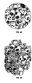
- Figs. 6A and 6B are end and perspective views, respectively, of a plug-shaped ceramic foam catalyst support according to another embodiment of the invention.
- Fig. 7 is a perspective view, partially cut away, of the ceramic foam catalyst support of Figs. 6A and 6B packed in a tube of the reforming exchanger according to the invention.
- Fig. 8 is a bar chart comparing the heat transfer/pressure drop ratio for ribbed ring, Raschig ring and foam catalyst supports in 1.38-in. or 1.05-in. inside diameter (ID) tubes, and for ribbed rings in a 1.94-in. ID tube, in a reforming exchanger, relative to Raschig rings in a 1.94-in. ID tube.
-
- Referring to Fig. 1, there is shown a reforming
exchanger 100 generally built according to the disclosures in the LeBlanc and Cizmar et al. patents mentioned above, and also incorporating the principles of the present invention. The reformingexchanger 100 has a tubeside fluid inlet 102, shellside fluid inlet 104, and shellside fluid outlet 106 in anelongated shell 108 having respective relatively high and low temperature ends 110 and 112, respectively. The shellside fluid inlet 104 is adjacent to thehigh temperature end 110 for receiving a hot gas feed. The tubeside fluid inlet 102 is adjacent to thelow temperature end 112 for receiving a feed mixture of hydrocarbon and steam. The shellside fluid outlet 106 is fluidly isolated from the tubeside fluid inlet 102 bytube sheet 114 that is adjacent to thelow temperature end 112 for discharging cooled gas from the reformingexchanger 100. - A
tube bundle 116 is made up of a plurality oftubes 118 and one or more longitudinally spacedtransverse baffle plates 120. Thetubes 118 have aninlet end 122 secured to thetube sheet 114 for receiving the gas mixture, and anoutlet end 124 that is adjacent to the shellside fluid inlet 104 for discharging reformed gas into the hot gas feed. Low pressure drop (ΔP) catalyst-bearing monolithic structures (see Figs. 2-7) are disposed within the tubes for converting the gas feed mixture to reformed gas. - The
tubes 118 preferably have a ratio of Lt/Dt of at least 300, more preferably at least 450 - 500. In determining Lt/Dt, the diameter Dt refers to the inside diameter of thetubes 118 in the case of right circular cylindrical tubes, or to the equivalent hydraulic diameter in the case of non-circular tubes. The length Lt refers to the catalyst-filled or -packed length. Higher Lt/Dt ratios are preferred in the present invention because the heat transfer coefficients are generally higher than with a lower Lt/Dt ratio, and the resulting equipment cost is lower. A longer, smaller-ID catalyst tube 118 generally results inmore tubes 118 in thetube bundle 116, but thetube bundle 116 has a smaller diameter for a given conversion capacity, allowing the use of ashell 108 that has a smaller diameter. In general, the reduction of the diameter of theshell 108 andtube bundle 116 results in more capital cost savings than result from any increase in the length thereof, and thus the reformingexchanger 100 of the present invention can be much cheaper to fabricate than a prior art reforming exchanger of equivalent capacity. This result is particularly advantageous in the design of a new reformingexchanger 100. - Or, if it is desired to use the same shell diameters and tube lengths of a prior art reforming exchanger so that the capital costs thereof are substantially equivalent, then the conversion capacity of the reforming
exchanger 100 is substantially increased. This latter result is particularly advantageous in the retrofitting of existing reforming exchangers by replacing the existing tube bundle with atube bundle 116 that has relatively more smaller-ID tubes 118 so that the retrofitted reformingexchanger 100 has a higher capacity than the original reforming exchanger. - In the present invention, the ratio of the tube inside diameter (ID), Dt, to the largest edge dimension of the catalyst structure (Dp) can be relatively small compared to the same ratio in conventional reforming exchangers. For example, in prior art reforming exchangers employing Raschig ring catalyst measuring 0.31-in. OD by 0.125-in. ID by 0.31-in. long, the minimum tube ID was about 2 inches. In the present invention, the same Raschig ring catalyst can be used in approximately 1.25-in. or even 1-in. ID tubes with an equivalent or slightly higher ratio of heat transfer to pressure drop. In the present invention, the Dt/Dp ratio is preferably not more than 4, and more preferably about 3 or less.
- A low ΔP catalyst structure is defined herein as any suitable catalyst structure that results in a higher rate of heat transfer per unit of tube side pressure drop than in 2-in. ID reforming exchanger tubes filled with catalyst-supporting Raschig rings measuring 0.31-in. OD by 0.125-in. ID by 0.31-in. long under similar operating conditions and conversions.
- Several different types of low ΔP monolithic catalyst support structures are contemplated as being useful in the present invention. While the low ΔP is the most important property in the present invention, the exemplary catalysts are also typically found to have a relatively high void fraction and present a tortuous flow path to the tube side fluid. Catalyst activity can be relatively low to moderate without significant reduction in conversion rates, although there is no general detriment to using a high activity catalyst aside from the typically higher cost involved.
- With reference to Figs. 2A, 2B and 3, the
catalyst support 200 is a ribbed ring catalyst structure comprising an overall cylindrical shape with a centrallongitudinal bore 202 andexterior ribs 204 running parallel to a longitudinal axis. The depth of the V-shapedchannel 206 between the ribs is preferably from 0.1 to 0.3 times the OD of thesupport 200.Supports 200 measuring 2.362-in. (6 mm) OD by 0.787-in. (2 mm) ID by 2.362-in. (6 mm) long with afin 204 height of 0.787-in. (2 mm) comprise one example of a suitably dimensionedsupport 200 for use in nominal 1-inch or 1.5-inch tubes. - The ribbed ring supports 200 can be made by pressing a ceramic precursor into molds with a pin to make the
central bore 202, followed by calcining the material at elevated temperatures, e.g. 2500°F, to form a ribbed ring support made of an α-alumina, for example, and impregnating the α-alumina with nickel or another suitable catalytically active material. Ribbed ring catalyst is commercially available, for example, from Süd-Chemie Inc. of Louisville, Kentucky. Because of the relatively large size of the ribbed ring catalyst compared to thetube 118 ID, the catalyst should preferably be loaded into thetubes 118 using a dense loading method such as is accomplished with the equipment and methodology described in U.S. Patents 6,132,157, 5,897,282, and 5,890,868, which are hereby incorporated herein by reference, in order to minimize any packing or bridging problems. - With reference to Fig. 4, the
catalyst insert 300 is in the form of a twisted tape having an OD about the same as the ID of thetube 118 in which it is used. The OD of theinsert 300 is slightly less than the ID of thetube 118 to facilitate placement of thetape insert 300. The length of theinsert 300 can be essentially the same length as the tube with oneinsert 300 in eachtube 118, ormultiple inserts 300 can be placed end-to-end in eachtube 118. For themultiple inserts 300, eachinsert 300 preferably has a length which is at least as great as the diameter in order to keep theinserts 300 longitudinally aligned in thetube 118. Theinsert 300 can be made of a catalytically active material such as nickel, or it can be coated with a catalytically active material. For example, theinsert 300 can be wash coated with a ceramic as described in U.S. Patents 5,980,843 to Silversand or 5,935,889 to Murrell et al., both of which are hereby incorporated herein by reference in their entireties, and the ceramic coating impregnated with a nickel catalyst by conventional ceramic impregnation techniques. Catalytically inactive forms ofsuch inserts 300 are commercially available for increasing the tube side heat transfer coefficients in a shell-and-tube heat exchanger from, for example, the Brown Fintube Company of Houston, Texas. - With reference to Fig. 5, the
catalyst insert 400 is in the form of a brush comprising a central runner 402 and a plurality of bristles or filaments 404 extending transversely therefrom. Thebrush insert 400 has an OD about the same as the ID of thetube 118 in which it is used. The length of theinsert 400 can be essentially the same length as thetube 118 with oneinsert 400 in eachtube 118, ormultiple inserts 400 can be placed end-to-end in eachtube 118, optionally with some overlap. For themultiple inserts 400, eachinsert 400 should have a length which is at least several times as great as the diameter in order to keep theinserts 400 longitudinally aligned in thetube 118. Theinsert 400 can be made of a catalytically active material such as nickel, or it can be coated with a catalytically active material. For example, theinsert 400 can be wash coated with a ceramic as described above, and the ceramic coating impregnated with a nickel catalyst by conventional ceramic impregnation techniques. Catalytically inactive forms ofsuch inserts 400 are commercially available for increasing the tube side heat transfer coefficients in a shell-and-tube heat exchanger under, for example, the trade designation HITRAN. - With reference to Figs. 6A, 6B and 7, the
catalyst insert 500 is in the form of a ceramic foam. Theceramic foam insert 500 is preferably made by filling voids in an organic sponge substrate with a fluidized ceramic precursor and burning the substrate away to form the ceramic foam. The ceramic foam can be impregnated with nickel or another catalytically active material using conventional nickel impregnation techniques. Theceramic foam insert 500 is preferably made in sheets, plugs 502 are cut from the sheets having a diameter less than a thickness, and a plurality of theplugs 502 are stacked end-to-end in eachtube 118. If necessary, the sheet can be filled with liquid wax, which is solidified to facilitate the cutting of theplugs 502, and then the wax is removed by melting it. Theplug 502 has an OD about the same as the ID of thetube 118 in which it is used. The length of eachplug 502 should be at least as great as the ID of thetube 118 to help keep theplug 502 aligned inside thetube 118. Theplugs 502 are placed end-to-end in eachtube 118 as illustrated in Fig. 7. - In the following examples, the tube side heat transfer coefficients, flow rates and pressure drops are based on a tube side inlet gas having the composition in Table 1:
-
Component Mole Percent N2 0.23 H2 0.34 CH4 15.49 Ar <0.01 CO2 0.03 C2H6 1.03 C3H8 0.34 iC4H10 0.10 iC5H12 0.02 nC6 0.02 CO 0.00 H2O 82.40 Total 100.00 - Conceptual sizing reviews were done on various types of catalyst sizes and tube inserts. The catalyst was of a normal size currently used in reforming exchangers available from Kellogg Brown & Root, Inc. under the trade designation KRES (Raschig rings 0.31-in. OD by 0.125-in. ID by 0.31-in. long), a smaller catalyst size (Raschig rings 0.25-in. OD by 0.10-in. ID by 0.25-in. long), a smallest catalyst size (Raschig rings 0.185-in. OD by 0.07-in. ID by 0.185-in. long), a twisted tape insert such as a Turbulator available from Brown Fintube but made of nickel 201 (99.6% nickel), and a ceramic foam insert impregnated with nickel. The results are summarized in Table 2:
Parameter Base Case Comparative Example A Comparative Example B Comparative Example C Example 1 Example 2 Catalyst Normal (0.31 x0.125 x0.31) Smaller (0.25 x0.10 x0.25) Smallest (0.185 x0.07 x0.185) Solid Pellets (0.185 x0.185) Twisted tape Ceramic foam Refractory ID (in.) 103 114 110 120 48 88 Tube length (ft) 44 44 27 24 60 41 Tube OD (in.) 2 2.5 1.5 1.5 0.75 1.15 Relative no. of tubes Base 0.79 2.03 2.33 1.61 1.62 Relative surface area Base 0.986 0.936 0.954 0.822 0.833 Tube ΔP (psi) 28 29 28 27 10 29 Shell side ΔP (psi) 8 8 8 8 8 8 MTD (°F) 145.5 153.2 140.7 135.9 139.8 150 Overall U (Btu/hr-ft2-°F) 55.7 53.4 63.8 65.3 68.3 60.0 Approach to equilibrium (°F) 3.6 3.4 5.1 5.9 5.1 5.3 Estimated cost (relative) Base 1.06 0.96 0.99 0.37 0.48 - These results show little or no advantage in the use of the smaller or smallest drilled cylinder catalyst shapes, or solid cylindrical pellets, Comparative Examples A, B and C, respectively. The smaller catalyst sizes result in larger diameter reactors (refractory ID), assuming that the same allowable pressure drop is available, as in Comparative Examples A, B and C. Although the tube lengths are shorter in Comparative Examples B and C, the larger reactor diameters result in premium costs and also present problems in tubesheet fabrication and quality control.
- The designs with the twisted tape insert and the ceramic foam (Examples 1 and 2) use smaller diameter tubes and lattice or egg crate type baffles, resulting in longitudinal shell side flow and improved shell side performance. Combined with the enhanced tube side performance, this results in a more cost effective design with a lower pressure drop. Example 1 is based on the twisted insert measuring 0.625-in. wide by 0.035-in. thick and twisted to 4 revolutions per foot. Performance sizing assumed the same targeted methane slip (2.5%) and the same activity factors as with conventional catalysts. Nickel impregnation of a ceramic coating on the twisted tape insert can improve catalytic activity.
- Conceptual sizing reviews were done as in Examples 1-2 to compare the pressure drop and performance of Raschig ring catalyst against ribbed ring catalyst. Both catalyst structures measured 0.31-in. OD by 0.125-in. ID by 0.31-in. long, and the V-shaped grooves between the ribs on the ribbed ring catalyst were 0.17-in. deep. The results are presented in Table 3:
-
Parameter Comparative Example D Example 3 Catalyst 0.31 in. x 0.125 in. x 0.31 in. Raschig rings 0.31 in. x 0.125 in. x 0.31 in. ribbed rings Refractory ID (in.) 55 55 Tube length (ft) 25 25 Tube ID (in.) 2.00 2.00 Tube OD (in.) 2.25 2.25 Relative no. of tubes Base 1.0 Relative catalyst volume Base 1.0 Relative surface area Base 1.0 Tube ΔP (psi) 21.5 12.5 Shell side ΔP (psi) 8 8 MTD (°F) 211 225 Overall U (Btu/hr- ft2-°F) 51 48 Approach to equilibrium (°F) 33.4 29.1 Methane slip (%) 1.19 1.16 - The data for Example 3 demonstrate that the performance of the ribbed ring catalyst is generally equivalent to Raschig rings of the same size, except that the tube side pressure drop is substantially lower. The cost of the ribbed ring reforming exchanger with a correspondingly reduced number of relatively longer tubes would be much less since exchanger overall length is generally less expensive than exchanger diameter.
- Conceptual sizing reviews were done as in Examples 1-3 for various sizes of catalyst tube ID's (2.0, 1.55 and 1.00-in.) using standard Raschig ring catalyst. The results are presented in Table 4:
Parameter Comparative Example D Example 4 Example 5 Catalyst 0.31 in. x 0.125 in. x 0.31 in. Raschig rings 0.31 in. x 0.125 in. x 0.31 in. Raschig rings 0.31 in. x 0.125 in. x 0.31 in. Raschig rings Refractory ID (in.) 91.3 84.6 81.9 Tube length (ft) 40 35 25 Tube ID (in.) 2.00 1.55 1.00 Tube OD (in.) 2.25 1.75 1.125 Relative no. of tubes Base 1.43 2.91 Relative catalyst volume Base 0.75 0.45 Relative surface area Base 0.964 0.912 Tube ΔP (psi) 35.5 34.5 33.8 MTD (°F) 167.9 157.9 150.2 Overall U (Btu/hr-ft2-°F) 64.7 71.4 79.9 Approach to equilibrium (°F) 6.9 8.4 14.9 Estimated cost (relative) Base 0.84 0.64 - The data for Examples 4 and 5 show, quite surprisingly, that employing smaller tubes, i.e. a lower Dt/Dp ratio, using the conventional Raschig rings, has the result of significantly reducing the catalyst volume and cost of the reforming exchanger, while maintaining the same capacity.
- Tubes of various sizes were packed with catalyst shapes comprising Raschig rings, ribbed rings and ceramic foam plugs in a laboratory tube evaluation apparatus. Air was passed through the packed tubes at Reynold's numbers similar to those seen in commercial reforming reactor tubes. The tubes were externally heated to provide tube wall temperatures within a range expected in commercial reforming reactor tubes. Heat transfer coefficients (Btu/hr-ft2-°F) for the inside surface of the tubes were determined and pressure drop (psi/ft) was measured. The data were used to compare the ratio of heat transfer to pressure drop relative to a 1.94-in. ID tube with Raschig ring catalyst supports. The ratio was determined for Raschig rings and ribbed rings in 1.94-in. ID and 1.38-in. ID tubes, and for Raschig rings, ribbed rings and ceramic foam in 1.05-in. ID tubes. The results are presented in Fig. 8, and show that the relative ratio of heat transfer to tube side pressure drop is significantly higher for ribbed ring catalyst at all tube diameters, and for ceramic foam catalyst at the smaller tube diameter tested.
- The foregoing description and examples of the invention are merely illustrative thereof. Various changes and modifications will be obvious to the skilled artisan in view of the foregoing disclosure. All such variations that fall within the scope or spirit of the appended claims are intended to be embraced thereby.
- Syngas production process and reforming exchanger. The process involves passing a first portion of hydrocarbon feed mixed with steam and oxidant through an autothermal catalytic steam reforming zone to form a first reformed gas of reduced hydrocarbon content, passing a second portion of the hydrocarbon feed mixed with steam through an endothermic catalytic steam reforming zone to form a second reformed gas of reduced hydrocarbon content, and mixing the first and second reformed gases and passing the resulting gas mixture through a heat exchange zone for cooling the gas mixture and thereby supplying heat to the endothermic catalytic steam reforming zone. The endothermic catalytic steam reforming zone and the heat exchange zone are respectively disposed tube side and shell side within a shell-and-tube reforming exchanger. The reforming exchanger comprises a plurality of tubes packed with low pressure drop catalyst-bearing monolithic structures wherein an inside diameter of the tubes is less than 4 times a maximum edge dimension of the catalyst structures.
Claims (33)
- A syngas production process, comprising:wherein the endothermic catalytic steam reforming zone and the heat exchange zone are respectively disposed tube side and shell side within a shell-and-tube reforming exchanger comprising a plurality of tubes packed with catalyst-bearing monolithic structures, the tubes having an inside diameter that is not more than 4 times a maximum edge dimension of the catalyst structures; andpassing a first portion of a hydrocarbon feed mixed with steam and oxidant through an autothermal catalytic steam reforming zone to form a first reformed gas of reduced hydrocarbon content;passing a second portion of the hydrocarbon feed mixed with steam through an endothermic catalytic steam reforming zone to form a second reformed gas of reduced hydrocarbon content;mixing the first and second reformed gases and passing the resulting gas mixture through a heat exchange zone for cooling the gas mixture and supplying heat to the endothermic catalytic steam reforming zone;
recovering syngas comprising the cooled gas mixture. - Apparatus for reforming a hydrocarbon to produce syngas, comprising:wherein the endothermic catalytic steam reforming zone and the heat exchange zone are respectively disposed tube side and shell side within a shell-and-tube reforming exchanger comprising a plurality of tubes packed with catalyst-bearing monolithic structures, the tubes having an inside diameter that is not more than 4 times a maximum edge dimension of the catalyst structures; andmeans for passing a first portion of a hydrocarbon feed mixed with steam and oxidant through an autothermal catalytic steam reforming zone to form a first reformed gas of reduced hydrocarbon content;means for passing a second portion of the hydrocarbon feed mixed with steam through an endothermic catalytic steam reforming zone to form a second reformed gas of reduced hydrocarbon content;means for mixing the first and second reformed gases and passing the resulting gas mixture through a heat exchange zone for cooling the gas mixture and supplying heat to the endothermic catalytic steam reforming zone;
means for recovering syngas comprising the cooled gas mixture. - A syngas reforming exchanger, comprising:an elongated shell having relatively high and low temperature ends;a shell side fluid inlet adjacent the high temperature end for receiving a hot gas feed;a tube side fluid inlet adjacent the low temperature end for receiving a feed mixture of hydrocarbon and steam;a shell side fluid outlet fluidly isolated from the tube side fluid inlet by a tube sheet adjacent the low temperature end for discharging cooled gas;a tube bundle comprising a plurality of tubes and one or more longitudinally-spaced transverse baffle plates, wherein the tubes have an inlet end secured to the tube sheet for receiving the feed mixture and an outlet end adjacent the shell side fluid inlet for discharging reformed gas into the hot gas feed;catalyst-bearing monolithic structures disposed within the tubes for converting the gas feed mixture to reformed gas, wherein the tubes have an inside diameter that is not more than 4 times a maximum edge dimension of the catalyst structures.
- The invention of claim 1 wherein the tubes have an Lt/Dt ratio of at least 300 wherein Lt is taken as the length of the catalyst bearing extent of the tubes and Dt is the inside diameter of the tubes.
- The invention of claim 2 wherein the tubes have an Lt/Dt ratio of at least 300 wherein Lt is taken as the length of the catalyst bearing extent of the tubes and Dt is the inside diameter of the tubes.
- The invention of claim 3 wherein the tubes have an Lt/Dt ratio of at least 300 wherein Lt is taken as the length of the catalyst bearing extent of the tubes and Dt is the inside diameter of the tubes.
- The invention of claim 4 wherein an overall heat transfer rate is at least 5 percent greater for a given pressure drop than Raschig rings measuring 0.31-in. long by 0.31-in. outside diameter by 0.125-in. inside diameter in tubes having an inside diameter of 2-in.
- The invention of claim 5 wherein an overall heat transfer rate is at least 5 percent greater for a given pressure drop than Raschig rings measuring 0.31-in. long by 0.31-in. outside diameter by 0.125-in. inside diameter in tubes having an inside diameter of 2-in.
- The invention of claim 6 wherein an overall heat transfer rate is at least 5 percent greater for a given pressure drop than Raschig rings measuring 0.31-in. long by 0.31-in. outside diameter by 0.125-in. inside diameter in tubes having an inside diameter of 2-in.
- The invention of claim 1 wherein the catalyst-bearing monolithic structures comprise a twisted tape insert.
- The invention of claim 4 wherein the catalyst-bearing monolithic structures comprise a twisted tape insert with a wash-coated surface impregnated with a nickel-containing catalyst.
- The invention of claim 2 wherein the catalyst-bearing monolithic structures comprise a twisted tape insert.
- The invention of claim 5 wherein the catalyst-bearing monolithic structures comprise a twisted tape insert with a wash-coated surface impregnated with a nickel-containing catalyst.
- The invention of claim 3 wherein the catalyst-bearing monolithic structures comprise a twisted tape insert.
- The invention of claim 6 wherein the catalyst-bearing monolithic structures comprise a twisted tape insert with a wash-coated surface impregnated with a nickel-containing catalyst.
- The invention of claim 1 wherein the catalyst-bearing monolithic structures comprise a central longitudinal runner and a plurality of bristles extending transversely therefrom.
- The invention of claim 4 wherein the catalyst-bearing monolithic structures comprise a central longitudinal runner, a plurality of bristles extending transversely therefrom and the bristles are wash-coated and impregnated with a nickel-containing catalyst.
- The invention of claim 2 wherein the catalyst-bearing monolithic structures comprise a central longitudinal runner and a plurality of bristles extending transversely therefrom.
- The invention of claim 5 wherein the catalyst-bearing monolithic structures comprise a central longitudinal runner, a plurality of bristles extending transversely therefrom and the bristles are wash-coated and impregnated with a nickel-containing catalyst.
- The invention of claim 3 wherein the catalyst-bearing monolithic structures comprise a central longitudinal runner and a plurality of bristles extending transversely therefrom.
- The invention of claim 6 wherein the catalyst-bearing monolithic structures comprise a central longitudinal runner, a plurality of bristles extending transversely therefrom and the bristles are wash-coated and impregnated with a nickel-containing catalyst.
- The invention of claim 1 wherein the catalyst-bearing monolithic structures comprise ceramic foam.
- The invention of claim 4 wherein the catalyst-bearing monolithic structures comprise ceramic foam made by filling voids in a sponge substrate with a fluidized ceramic and burning the substrate away to form the ceramic foam.
- The invention of claim 23 wherein the ceramic foam is made in sheets, plugs are cut from the sheet having a diameter less than a thickness, and a plurality of the plugs are stacked end-to-end in each tube.
- The invention of claim 2 wherein the catalyst-bearing monolithic structures comprise ceramic foam.
- The invention of claim 5 wherein the catalyst-bearing monolithic structures comprise ceramic foam made by filling voids in a sponge substrate with a fluidized ceramic and burning the substrate away to form the ceramic foam.
- The invention of claim 26 wherein the ceramic foam is made in sheets, plugs are cut from the sheet having a diameter less than a thickness, and a plurality of the plugs are stacked end-to-end in each tube.
- The invention of claim 3 wherein the catalyst-bearing monolithic structures comprise ceramic foam.
- The invention of claim 6 wherein the catalyst-bearing monolithic structures comprise ceramic foam made by filling voids in a sponge substrate with a fluidized ceramic and burning the substrate away to form the ceramic foam.
- The invention of claim 29 wherein the ceramic foam is made in sheets, plugs are cut from the sheet having a diameter less than a thickness, and a plurality of the plugs are stacked end-to-end in each tube.
- The invention of claim 1 wherein the catalyst-bearing monolithic structures comprise Raschig rings.
- The invention of claim 2 wherein the catalyst-bearing monolithic structures comprise Raschig rings.
- The invention of claim 3 wherein the catalyst-bearing monolithic structures comprise Raschig rings.
Applications Claiming Priority (2)
| Application Number | Priority Date | Filing Date | Title |
|---|---|---|---|
| US09/908,307 US6855272B2 (en) | 2001-07-18 | 2001-07-18 | Low pressure drop reforming exchanger |
| US908307 | 2001-07-18 |
Publications (3)
| Publication Number | Publication Date |
|---|---|
| EP1277698A2 true EP1277698A2 (en) | 2003-01-22 |
| EP1277698A3 EP1277698A3 (en) | 2004-03-24 |
| EP1277698B1 EP1277698B1 (en) | 2006-10-04 |
Family
ID=25425562
Family Applications (1)
| Application Number | Title | Priority Date | Filing Date |
|---|---|---|---|
| EP02014634A Expired - Lifetime EP1277698B1 (en) | 2001-07-18 | 2002-07-02 | Low pressure drop heat exchange reformer |
Country Status (10)
| Country | Link |
|---|---|
| US (2) | US6855272B2 (en) |
| EP (1) | EP1277698B1 (en) |
| KR (1) | KR100695052B1 (en) |
| CN (1) | CN100448949C (en) |
| AT (1) | ATE341525T1 (en) |
| CA (1) | CA2389638C (en) |
| DE (1) | DE60215080T2 (en) |
| ES (1) | ES2269566T3 (en) |
| MX (1) | MXPA02006987A (en) |
| NO (1) | NO20023422L (en) |
Cited By (15)
| Publication number | Priority date | Publication date | Assignee | Title |
|---|---|---|---|---|
| WO2004101141A1 (en) * | 2003-05-07 | 2004-11-25 | Shell Internationale Research Maatschappij B.V. | A reactor system and process for the manufacture of ethylene oxide |
| DE10359205A1 (en) * | 2003-12-17 | 2005-07-14 | Webasto Ag | Reformer and method for converting fuel and oxidant to reformate |
| US6936238B2 (en) * | 2002-09-06 | 2005-08-30 | General Motors Corporation | Compact partial oxidation/steam reactor with integrated air preheater, fuel and water vaporizer |
| EP1603831A2 (en) * | 2003-03-16 | 2005-12-14 | Kellogg Brown & Root, Inc. | Partial oxidation reformer-reforming exchanger arrangement |
| WO2005065187A3 (en) * | 2003-12-31 | 2006-01-05 | Corning Inc | Multi-tubular reactors with monolithic catalysts |
| EP1650160A1 (en) * | 2004-10-20 | 2006-04-26 | Stichting Energieonderzoek Centrum Nederland | Process for the production of synthesis gas and reactor for such process |
| WO2006045457A1 (en) * | 2004-10-26 | 2006-05-04 | Haldor Topsøe A/S | Reactor and process for carrying out endothermic or exothermic catalytic reactions |
| WO2006045746A1 (en) * | 2004-10-20 | 2006-05-04 | Shell Internationale Research Maatschappij B.V. | Process to prepare a mixture of carbon monoxide and hydrogen |
| WO2006051098A1 (en) * | 2004-11-12 | 2006-05-18 | Shell Internationale Research Maatschappij B.V. | Tubular reactor with packing |
| DE102006033441A1 (en) * | 2006-06-29 | 2008-01-03 | Webasto Ag | Reformer for a fuel cell system |
| US7501078B2 (en) | 2007-01-10 | 2009-03-10 | Air Products And Chemicals, Inc. | Process for generating synthesis gas using catalyzed structured packing |
| EP2140933A1 (en) * | 2008-07-02 | 2010-01-06 | Werner Soyez | Structured catalyst hold for pipe reactors |
| US7932296B2 (en) | 2003-03-16 | 2011-04-26 | Kellogg Brown & Root Llc | Catalytic partial oxidation reforming for syngas processing and products made therefrom |
| US8273139B2 (en) | 2003-03-16 | 2012-09-25 | Kellogg Brown & Root Llc | Catalytic partial oxidation reforming |
| EP2828503A4 (en) * | 2012-03-23 | 2016-03-09 | United Technologies Corp | Catalytic reaction in confined flow channel |
Families Citing this family (27)
| Publication number | Priority date | Publication date | Assignee | Title |
|---|---|---|---|---|
| US6855272B2 (en) * | 2001-07-18 | 2005-02-15 | Kellogg Brown & Root, Inc. | Low pressure drop reforming exchanger |
| EP1413547A1 (en) * | 2002-09-26 | 2004-04-28 | Haldor Topsoe A/S | Process for the production of synthesis gas |
| ATE502894T1 (en) * | 2002-09-26 | 2011-04-15 | Haldor Topsoe As | METHOD FOR PRODUCING SYNTHESIS GAS |
| US7220505B2 (en) * | 2003-03-18 | 2007-05-22 | Kellogg Brown & Root Llc | Autothermal reformer-reforming exchanger arrangement for hydrogen production |
| US20040225138A1 (en) * | 2003-05-07 | 2004-11-11 | Mcallister Paul Michael | Reactor system and process for the manufacture of ethylene oxide |
| AU2005289799A1 (en) | 2004-09-24 | 2006-04-06 | Shell Internationale Research Maatschappij B.V. | A process for selecting shaped particles, a process for installing a system, a process for reacting a gaseous feedstock in such a system, a computer program product, and a computer system |
| GB0507269D0 (en) * | 2005-04-11 | 2005-05-18 | Johnson Matthey Plc | Steam reforming |
| US7293533B2 (en) * | 2005-08-08 | 2007-11-13 | Utilization Technology Development, Nfp | Recuperative reforming reactor |
| KR100674864B1 (en) * | 2005-09-29 | 2007-01-29 | 삼성전기주식회사 | Reforming apparatus for fuel cell |
| US7207323B1 (en) | 2006-01-06 | 2007-04-24 | Utilization Technology Development, Nfp | Catalytic core reactor for thermochemical heat recovery |
| US20080016768A1 (en) | 2006-07-18 | 2008-01-24 | Togna Keith A | Chemically-modified mixed fuels, methods of production and used thereof |
| US7635456B2 (en) * | 2006-08-08 | 2009-12-22 | Kellogg Brown & Root Llc | Low pressure drop reforming reactor |
| US7887764B2 (en) * | 2007-09-18 | 2011-02-15 | Jernberg Gary R | Mixer with a catalytic surface |
| CA2623407A1 (en) * | 2008-02-28 | 2009-08-28 | Hydro-Quebec | Composite electrode material |
| US8278363B2 (en) * | 2009-03-23 | 2012-10-02 | Thomas Charles Holcombe | Fischer-tropsch reactions using heat transfer tubes with a catalyst layer on the outside surfaces |
| CN101818075B (en) * | 2010-04-29 | 2013-06-12 | 华南理工大学 | Method for reducing re-contact process energy consumption of catalytic reforming device |
| DE102011107933A1 (en) * | 2011-07-19 | 2013-01-24 | Thyssenkrupp Uhde Gmbh | Apparatus useful for passing gas through heatable reaction tube and carrying out endothermic reaction of gas in catalyst system, comprises heatable reaction tube comprising catalyst, an input portion and an output portion |
| WO2013044444A1 (en) * | 2011-09-27 | 2013-04-04 | 中国科学院宁波材料技术与工程研究所 | Catalytic reforming hydrogen production method and catalytic unit |
| CN103011077B (en) * | 2011-09-27 | 2016-04-06 | 中国科学院宁波材料技术与工程研究所 | A kind of catalytically reforming hydrogen producing method and catalytic unit |
| US8545775B2 (en) | 2011-10-20 | 2013-10-01 | Kellogg Brown & Root Llc | Reforming exchanger system with intermediate shift conversion |
| US9101899B2 (en) | 2011-10-20 | 2015-08-11 | Kellogg Brown & Root Llc | Reforming exchanger with integrated shift conversion |
| CA2862527C (en) * | 2012-02-06 | 2021-06-29 | Helbio Societe Anonyme Hydrogen And Energy Production Systems | Heat integrated reformer with catalytic combustion for hydrogen production |
| RU2554008C1 (en) | 2014-01-13 | 2015-06-20 | Общество с ограниченной ответственностью "Газохим Техно" | Reactor for partial oxidation of hydrocarbon gases |
| WO2016049326A1 (en) | 2014-09-24 | 2016-03-31 | Intellergy, Inc. | Compact and maintainable waste reformation apparatus |
| ITUB20150576A1 (en) * | 2015-04-24 | 2016-10-24 | Hexsol Italy Srl | HEAT EXCHANGER WITH BUNDLE TUBE AND IMPROVED STRUCTURE |
| US11052364B2 (en) * | 2016-02-08 | 2021-07-06 | Kt Kinetics Technology Spa | Enhanced efficiency endothermic reactor for syngas production with flexible heat recovery to meet low export steam generation |
| EP3900820A1 (en) * | 2020-09-21 | 2021-10-27 | Haldor Topsøe A/S | Double tubes combined heat exchanger and steam reformer reactor comprising two types of catalyst beds |
Citations (5)
| Publication number | Priority date | Publication date | Assignee | Title |
|---|---|---|---|---|
| DE1542473A1 (en) * | 1966-08-10 | 1970-03-26 | Schmidt Dipl Phys Herbert | Process and device for catalytic, chemical and physical reactions in the phases gaseous, liquid, gaseous-liquid, gaseous-solid, liquid-solid and solid |
| US4400309A (en) * | 1972-06-30 | 1983-08-23 | Foster Wheeler Energy Corporation | Process for activating a steam reforming catalyst and the catalyst produced by the process |
| US5011625A (en) * | 1989-12-11 | 1991-04-30 | The M. W. Kellogg Company | Autothermal steam reforming process |
| US5362454A (en) * | 1993-06-28 | 1994-11-08 | The M. W. Kellogg Company | High temperature heat exchanger |
| US5718881A (en) * | 1996-06-24 | 1998-02-17 | International Fuel Cells, Inc. | Catalytic reactor designed to reduce catalyst slumping and crushing |
Family Cites Families (22)
| Publication number | Priority date | Publication date | Assignee | Title |
|---|---|---|---|---|
| US3864083A (en) * | 1970-06-26 | 1975-02-04 | Exxon Research Engineering Co | Carbon Detection |
| JPS52112607A (en) * | 1976-03-09 | 1977-09-21 | Agency Of Ind Science & Technol | Reformers |
| DE3068525D1 (en) | 1979-09-06 | 1984-08-16 | Ici Plc | A process and apparatus for catalytically reacting steam with a hydrocarbon in endothermic conditions |
| US4363787A (en) | 1979-12-18 | 1982-12-14 | Conoco Inc. | Monolith heat exchange reactor |
| JPS5817841A (en) * | 1981-07-24 | 1983-02-02 | Mitsubishi Heavy Ind Ltd | Catalyst with short fiber carrier for treatment of gas |
| US4822521A (en) * | 1983-06-09 | 1989-04-18 | Uop | Integrated process and apparatus for the primary and secondary catalytic steam reforming of hydrocarbons |
| DE3532413A1 (en) * | 1985-09-11 | 1987-03-12 | Uhde Gmbh | DEVICE FOR GENERATING SYNTHESIS GAS |
| DE3765377D1 (en) * | 1986-09-10 | 1990-11-08 | Ici Plc | CATALYSTS. |
| US6153152A (en) * | 1990-04-03 | 2000-11-28 | The Standard Oil Company | Endothermic reaction apparatus and method |
| CO4370053A1 (en) | 1993-11-29 | 1996-10-07 | Shell Int Research | PROCESS FOR PARTIAL CATALYTIC OXIDATION OF HYDROCARBONS |
| TW299345B (en) * | 1994-02-18 | 1997-03-01 | Westinghouse Electric Corp | |
| SE504795C2 (en) * | 1995-07-05 | 1997-04-28 | Katator Ab | Network-based combustion catalyst and production thereof |
| US5897282A (en) * | 1996-10-01 | 1999-04-27 | Comardo; Mathis P. | Catalytic reactor charging system and method for operation thereof |
| US5935889A (en) * | 1996-10-04 | 1999-08-10 | Abb Lummus Global Inc. | Catalyst and method of preparation |
| EP0936182A3 (en) * | 1998-02-13 | 2000-02-23 | Haldor Topsoe A/S | Method of soot-free start-up of autothermal reformers |
| DK173742B1 (en) * | 1998-09-01 | 2001-08-27 | Topsoe Haldor As | Process and reactor system for producing synthesis gas |
| US6579510B2 (en) | 1999-07-30 | 2003-06-17 | Alfred E. Keller | SPOX-enhanced process for production of synthesis gas |
| US6409940B1 (en) | 1999-10-18 | 2002-06-25 | Conoco Inc. | Nickel-rhodium based catalysts and process for preparing synthesis gas |
| WO2001060515A2 (en) | 2000-02-18 | 2001-08-23 | Conoco Inc. | Reticulated ceramic foam catalysts for synthesis gas production |
| EP1289879A2 (en) | 2000-06-13 | 2003-03-12 | Conoco Inc. | Supported nickel-magnesium oxide catalysts and processes for the production of syngas |
| US6855272B2 (en) * | 2001-07-18 | 2005-02-15 | Kellogg Brown & Root, Inc. | Low pressure drop reforming exchanger |
| US7635456B2 (en) * | 2006-08-08 | 2009-12-22 | Kellogg Brown & Root Llc | Low pressure drop reforming reactor |
-
2001
- 2001-07-18 US US09/908,307 patent/US6855272B2/en not_active Expired - Lifetime
-
2002
- 2002-06-06 CA CA2389638A patent/CA2389638C/en not_active Expired - Lifetime
- 2002-07-02 AT AT02014634T patent/ATE341525T1/en not_active IP Right Cessation
- 2002-07-02 DE DE60215080T patent/DE60215080T2/en not_active Expired - Lifetime
- 2002-07-02 EP EP02014634A patent/EP1277698B1/en not_active Expired - Lifetime
- 2002-07-02 ES ES02014634T patent/ES2269566T3/en not_active Expired - Lifetime
- 2002-07-12 KR KR1020020040685A patent/KR100695052B1/en active IP Right Grant
- 2002-07-17 MX MXPA02006987A patent/MXPA02006987A/en active IP Right Grant
- 2002-07-17 NO NO20023422A patent/NO20023422L/en not_active Application Discontinuation
- 2002-07-18 CN CNB021263035A patent/CN100448949C/en not_active Expired - Lifetime
-
2005
- 2005-01-05 US US10/905,460 patent/US8216531B2/en not_active Expired - Lifetime
Patent Citations (5)
| Publication number | Priority date | Publication date | Assignee | Title |
|---|---|---|---|---|
| DE1542473A1 (en) * | 1966-08-10 | 1970-03-26 | Schmidt Dipl Phys Herbert | Process and device for catalytic, chemical and physical reactions in the phases gaseous, liquid, gaseous-liquid, gaseous-solid, liquid-solid and solid |
| US4400309A (en) * | 1972-06-30 | 1983-08-23 | Foster Wheeler Energy Corporation | Process for activating a steam reforming catalyst and the catalyst produced by the process |
| US5011625A (en) * | 1989-12-11 | 1991-04-30 | The M. W. Kellogg Company | Autothermal steam reforming process |
| US5362454A (en) * | 1993-06-28 | 1994-11-08 | The M. W. Kellogg Company | High temperature heat exchanger |
| US5718881A (en) * | 1996-06-24 | 1998-02-17 | International Fuel Cells, Inc. | Catalytic reactor designed to reduce catalyst slumping and crushing |
Non-Patent Citations (1)
| Title |
|---|
| FRENI S ET AL: "Hydrogen production from methane through catalytic partial oxidation reactions" JOURNAL OF POWER SOURCES, ELSEVIER SEQUOIA S.A. LAUSANNE, CH, vol. 87, no. 1-2, April 2000 (2000-04), pages 28-38, XP004194181 ISSN: 0378-7753 * |
Cited By (26)
| Publication number | Priority date | Publication date | Assignee | Title |
|---|---|---|---|---|
| DE10338240B4 (en) * | 2002-09-06 | 2006-08-03 | General Motors Corp., Detroit | Compact partial oxidation / steam reactor with integrated air preheater and fuel and hydrogen evaporator |
| US6936238B2 (en) * | 2002-09-06 | 2005-08-30 | General Motors Corporation | Compact partial oxidation/steam reactor with integrated air preheater, fuel and water vaporizer |
| EP1603831A2 (en) * | 2003-03-16 | 2005-12-14 | Kellogg Brown & Root, Inc. | Partial oxidation reformer-reforming exchanger arrangement |
| US7932296B2 (en) | 2003-03-16 | 2011-04-26 | Kellogg Brown & Root Llc | Catalytic partial oxidation reforming for syngas processing and products made therefrom |
| EP1603831A4 (en) * | 2003-03-16 | 2009-08-26 | Kellogg Brown & Root Inc | Partial oxidation reformer-reforming exchanger arrangement |
| US8273139B2 (en) | 2003-03-16 | 2012-09-25 | Kellogg Brown & Root Llc | Catalytic partial oxidation reforming |
| AU2004238819B2 (en) * | 2003-05-07 | 2008-05-01 | Shell Internationale Research Maatschappij B.V. | A reactor system and process for the manufacture of ethylene oxide |
| JP2007531612A (en) * | 2003-05-07 | 2007-11-08 | シエル・インターナシヨナル・リサーチ・マートスハツペイ・ベー・ヴエー | Reactor system and process for producing ethylene oxide |
| WO2004101141A1 (en) * | 2003-05-07 | 2004-11-25 | Shell Internationale Research Maatschappij B.V. | A reactor system and process for the manufacture of ethylene oxide |
| DE10359205B4 (en) * | 2003-12-17 | 2007-09-06 | Webasto Ag | Reformer and method for converting fuel and oxidant to reformate |
| DE10359205A1 (en) * | 2003-12-17 | 2005-07-14 | Webasto Ag | Reformer and method for converting fuel and oxidant to reformate |
| WO2005065187A3 (en) * | 2003-12-31 | 2006-01-05 | Corning Inc | Multi-tubular reactors with monolithic catalysts |
| CN100464831C (en) * | 2003-12-31 | 2009-03-04 | 康宁股份有限公司 | Multi-tubular reactors with monolithic catalysts |
| WO2006062403A2 (en) * | 2004-10-20 | 2006-06-15 | Stichting Energieonderzoek Centrum Nederland | Process for the production of synthesis gas and reactor for such process |
| WO2006062403A3 (en) * | 2004-10-20 | 2006-09-14 | Stichting Energie | Process for the production of synthesis gas and reactor for such process |
| WO2006045746A1 (en) * | 2004-10-20 | 2006-05-04 | Shell Internationale Research Maatschappij B.V. | Process to prepare a mixture of carbon monoxide and hydrogen |
| EP1650160A1 (en) * | 2004-10-20 | 2006-04-26 | Stichting Energieonderzoek Centrum Nederland | Process for the production of synthesis gas and reactor for such process |
| WO2006045457A1 (en) * | 2004-10-26 | 2006-05-04 | Haldor Topsøe A/S | Reactor and process for carrying out endothermic or exothermic catalytic reactions |
| US7776285B2 (en) | 2004-10-26 | 2010-08-17 | Haldor Topsøe A/S | Reactor and process for carrying out endothermic or exothermic catalytic reaction |
| WO2006051098A1 (en) * | 2004-11-12 | 2006-05-18 | Shell Internationale Research Maatschappij B.V. | Tubular reactor with packing |
| DE102006033441B4 (en) * | 2006-06-29 | 2009-05-07 | Enerday Gmbh | Reformer for a fuel cell system |
| DE102006033441A1 (en) * | 2006-06-29 | 2008-01-03 | Webasto Ag | Reformer for a fuel cell system |
| US7501078B2 (en) | 2007-01-10 | 2009-03-10 | Air Products And Chemicals, Inc. | Process for generating synthesis gas using catalyzed structured packing |
| EP2140933A1 (en) * | 2008-07-02 | 2010-01-06 | Werner Soyez | Structured catalyst hold for pipe reactors |
| EP2828503A4 (en) * | 2012-03-23 | 2016-03-09 | United Technologies Corp | Catalytic reaction in confined flow channel |
| US9295960B2 (en) | 2012-03-23 | 2016-03-29 | United Technologies Corporation | Catalytic reaction in confined flow channel |
Also Published As
| Publication number | Publication date |
|---|---|
| EP1277698B1 (en) | 2006-10-04 |
| US8216531B2 (en) | 2012-07-10 |
| MXPA02006987A (en) | 2003-02-24 |
| KR20030009151A (en) | 2003-01-29 |
| CA2389638A1 (en) | 2003-01-18 |
| EP1277698A3 (en) | 2004-03-24 |
| KR100695052B1 (en) | 2007-03-14 |
| CN1397629A (en) | 2003-02-19 |
| DE60215080D1 (en) | 2006-11-16 |
| US6855272B2 (en) | 2005-02-15 |
| DE60215080T2 (en) | 2007-02-22 |
| CN100448949C (en) | 2009-01-07 |
| CA2389638C (en) | 2010-12-14 |
| ATE341525T1 (en) | 2006-10-15 |
| NO20023422D0 (en) | 2002-07-17 |
| NO20023422L (en) | 2003-01-20 |
| US20050086864A1 (en) | 2005-04-28 |
| US20030064011A1 (en) | 2003-04-03 |
| ES2269566T3 (en) | 2007-04-01 |
Similar Documents
| Publication | Publication Date | Title |
|---|---|---|
| US6855272B2 (en) | Low pressure drop reforming exchanger | |
| JP2592662B2 (en) | Implementation of heterogeneous catalytic chemical processes | |
| US10246326B2 (en) | Steam reforming | |
| CA2508505C (en) | Heat exchange process and reactor | |
| US8168131B2 (en) | Low pressure drop reforming reactor | |
| US7731935B2 (en) | Steam reforming | |
| US20230415118A1 (en) | Reforming reactor comprising reformer tubes with enlarged outer surface area and structured catalyst | |
| US11731097B2 (en) | Catalyst particle shape | |
| US7776285B2 (en) | Reactor and process for carrying out endothermic or exothermic catalytic reaction | |
| WO2013059641A1 (en) | Reforming exchanger system with intermediate shift conversion | |
| EP1063008A2 (en) | Reactor for carrying out a non-adiabatic process | |
| JPH0230601A (en) | Apparatus for reforming methanol | |
| KR20220065027A (en) | Reactor tube assembly | |
| JP2004175580A (en) | Steam reformer | |
| EA045817B1 (en) | SHAPE OF CATALYST PARTICLES | |
| JP2003503294A (en) | Compact fuel gas reformer with combustor wall temperature control | |
| KR101769308B1 (en) | Fuel reformer with enhanced heat transfer abillity |
Legal Events
| Date | Code | Title | Description |
|---|---|---|---|
| PUAI | Public reference made under article 153(3) epc to a published international application that has entered the european phase |
Free format text: ORIGINAL CODE: 0009012 |
|
| AK | Designated contracting states |
Kind code of ref document: A2 Designated state(s): AT BE BG CH CY CZ DE DK EE ES FI FR GB GR IE IT LI LU MC NL PT SE SK TR |
|
| AX | Request for extension of the european patent |
Free format text: AL;LT;LV;MK;RO;SI |
|
| PUAL | Search report despatched |
Free format text: ORIGINAL CODE: 0009013 |
|
| AK | Designated contracting states |
Kind code of ref document: A3 Designated state(s): AT BE BG CH CY CZ DE DK EE ES FI FR GB GR IE IT LI LU MC NL PT SE SK TR |
|
| AX | Request for extension of the european patent |
Extension state: AL LT LV MK RO SI |
|
| RIC1 | Information provided on ipc code assigned before grant |
Ipc: 7C 01B 3/38 A Ipc: 7B 01J 35/02 B Ipc: 7B 01J 23/755 B Ipc: 7B 01J 8/02 B Ipc: 7B 01J 8/06 B Ipc: 7B 01J 8/00 B Ipc: 7C 01B 3/40 B Ipc: 7B 01J 35/04 B Ipc: 7B 01J 19/30 B |
|
| 17P | Request for examination filed |
Effective date: 20040624 |
|
| 17Q | First examination report despatched |
Effective date: 20040930 |
|
| AKX | Designation fees paid |
Designated state(s): AT BE BG CH CY CZ DE DK EE ES FI FR GB GR IE IT LI LU MC NL PT SE SK TR |
|
| GRAP | Despatch of communication of intention to grant a patent |
Free format text: ORIGINAL CODE: EPIDOSNIGR1 |
|
| GRAS | Grant fee paid |
Free format text: ORIGINAL CODE: EPIDOSNIGR3 |
|
| GRAA | (expected) grant |
Free format text: ORIGINAL CODE: 0009210 |
|
| AK | Designated contracting states |
Kind code of ref document: B1 Designated state(s): AT BE BG CH CY CZ DE DK EE ES FI FR GB GR IE IT LI LU MC NL PT SE SK TR |
|
| PG25 | Lapsed in a contracting state [announced via postgrant information from national office to epo] |
Ref country code: IT Free format text: LAPSE BECAUSE OF FAILURE TO SUBMIT A TRANSLATION OF THE DESCRIPTION OR TO PAY THE FEE WITHIN THE PRESCRIBED TIME-LIMIT;WARNING: LAPSES OF ITALIAN PATENTS WITH EFFECTIVE DATE BEFORE 2007 MAY HAVE OCCURRED AT ANY TIME BEFORE 2007. THE CORRECT EFFECTIVE DATE MAY BE DIFFERENT FROM THE ONE RECORDED. Effective date: 20061004 Ref country code: CZ Free format text: LAPSE BECAUSE OF FAILURE TO SUBMIT A TRANSLATION OF THE DESCRIPTION OR TO PAY THE FEE WITHIN THE PRESCRIBED TIME-LIMIT Effective date: 20061004 Ref country code: LI Free format text: LAPSE BECAUSE OF FAILURE TO SUBMIT A TRANSLATION OF THE DESCRIPTION OR TO PAY THE FEE WITHIN THE PRESCRIBED TIME-LIMIT Effective date: 20061004 Ref country code: CH Free format text: LAPSE BECAUSE OF FAILURE TO SUBMIT A TRANSLATION OF THE DESCRIPTION OR TO PAY THE FEE WITHIN THE PRESCRIBED TIME-LIMIT Effective date: 20061004 Ref country code: BE Free format text: LAPSE BECAUSE OF FAILURE TO SUBMIT A TRANSLATION OF THE DESCRIPTION OR TO PAY THE FEE WITHIN THE PRESCRIBED TIME-LIMIT Effective date: 20061004 Ref country code: SK Free format text: LAPSE BECAUSE OF FAILURE TO SUBMIT A TRANSLATION OF THE DESCRIPTION OR TO PAY THE FEE WITHIN THE PRESCRIBED TIME-LIMIT Effective date: 20061004 Ref country code: FI Free format text: LAPSE BECAUSE OF FAILURE TO SUBMIT A TRANSLATION OF THE DESCRIPTION OR TO PAY THE FEE WITHIN THE PRESCRIBED TIME-LIMIT Effective date: 20061004 Ref country code: AT Free format text: LAPSE BECAUSE OF FAILURE TO SUBMIT A TRANSLATION OF THE DESCRIPTION OR TO PAY THE FEE WITHIN THE PRESCRIBED TIME-LIMIT Effective date: 20061004 |
|
| REG | Reference to a national code |
Ref country code: GB Ref legal event code: FG4D |
|
| REG | Reference to a national code |
Ref country code: CH Ref legal event code: EP |
|
| REG | Reference to a national code |
Ref country code: IE Ref legal event code: FG4D |
|
| REF | Corresponds to: |
Ref document number: 60215080 Country of ref document: DE Date of ref document: 20061116 Kind code of ref document: P |
|
| PG25 | Lapsed in a contracting state [announced via postgrant information from national office to epo] |
Ref country code: SE Free format text: LAPSE BECAUSE OF FAILURE TO SUBMIT A TRANSLATION OF THE DESCRIPTION OR TO PAY THE FEE WITHIN THE PRESCRIBED TIME-LIMIT Effective date: 20070104 Ref country code: BG Free format text: LAPSE BECAUSE OF FAILURE TO SUBMIT A TRANSLATION OF THE DESCRIPTION OR TO PAY THE FEE WITHIN THE PRESCRIBED TIME-LIMIT Effective date: 20070104 Ref country code: DK Free format text: LAPSE BECAUSE OF FAILURE TO SUBMIT A TRANSLATION OF THE DESCRIPTION OR TO PAY THE FEE WITHIN THE PRESCRIBED TIME-LIMIT Effective date: 20070104 |
|
| REG | Reference to a national code |
Ref country code: GR Ref legal event code: EP Ref document number: 20060404463 Country of ref document: GR |
|
| PG25 | Lapsed in a contracting state [announced via postgrant information from national office to epo] |
Ref country code: PT Free format text: LAPSE BECAUSE OF FAILURE TO SUBMIT A TRANSLATION OF THE DESCRIPTION OR TO PAY THE FEE WITHIN THE PRESCRIBED TIME-LIMIT Effective date: 20070316 |
|
| REG | Reference to a national code |
Ref country code: ES Ref legal event code: FG2A Ref document number: 2269566 Country of ref document: ES Kind code of ref document: T3 |
|
| ET | Fr: translation filed | ||
| REG | Reference to a national code |
Ref country code: CH Ref legal event code: PL |
|
| PGFP | Annual fee paid to national office [announced via postgrant information from national office to epo] |
Ref country code: ES Payment date: 20070713 Year of fee payment: 6 |
|
| PLBE | No opposition filed within time limit |
Free format text: ORIGINAL CODE: 0009261 |
|
| STAA | Information on the status of an ep patent application or granted ep patent |
Free format text: STATUS: NO OPPOSITION FILED WITHIN TIME LIMIT |
|
| 26N | No opposition filed |
Effective date: 20070705 |
|
| PGFP | Annual fee paid to national office [announced via postgrant information from national office to epo] |
Ref country code: IT Payment date: 20070714 Year of fee payment: 6 Ref country code: NL Payment date: 20070619 Year of fee payment: 6 |
|
| PG25 | Lapsed in a contracting state [announced via postgrant information from national office to epo] |
Ref country code: MC Free format text: LAPSE BECAUSE OF NON-PAYMENT OF DUE FEES Effective date: 20070731 |
|
| PGFP | Annual fee paid to national office [announced via postgrant information from national office to epo] |
Ref country code: GR Payment date: 20070702 Year of fee payment: 6 |
|
| PG25 | Lapsed in a contracting state [announced via postgrant information from national office to epo] |
Ref country code: EE Free format text: LAPSE BECAUSE OF FAILURE TO SUBMIT A TRANSLATION OF THE DESCRIPTION OR TO PAY THE FEE WITHIN THE PRESCRIBED TIME-LIMIT Effective date: 20061004 |
|
| PG25 | Lapsed in a contracting state [announced via postgrant information from national office to epo] |
Ref country code: IE Free format text: LAPSE BECAUSE OF NON-PAYMENT OF DUE FEES Effective date: 20070702 |
|
| NLV4 | Nl: lapsed or anulled due to non-payment of the annual fee |
Effective date: 20090201 |
|
| PG25 | Lapsed in a contracting state [announced via postgrant information from national office to epo] |
Ref country code: NL Free format text: LAPSE BECAUSE OF NON-PAYMENT OF DUE FEES Effective date: 20090201 |
|
| PG25 | Lapsed in a contracting state [announced via postgrant information from national office to epo] |
Ref country code: GR Free format text: LAPSE BECAUSE OF NON-PAYMENT OF DUE FEES Effective date: 20090204 |
|
| PG25 | Lapsed in a contracting state [announced via postgrant information from national office to epo] |
Ref country code: LU Free format text: LAPSE BECAUSE OF NON-PAYMENT OF DUE FEES Effective date: 20070702 Ref country code: IT Free format text: LAPSE BECAUSE OF NON-PAYMENT OF DUE FEES Effective date: 20080702 Ref country code: CY Free format text: LAPSE BECAUSE OF FAILURE TO SUBMIT A TRANSLATION OF THE DESCRIPTION OR TO PAY THE FEE WITHIN THE PRESCRIBED TIME-LIMIT Effective date: 20061004 |
|
| REG | Reference to a national code |
Ref country code: ES Ref legal event code: FD2A Effective date: 20080703 |
|
| PG25 | Lapsed in a contracting state [announced via postgrant information from national office to epo] |
Ref country code: TR Free format text: LAPSE BECAUSE OF FAILURE TO SUBMIT A TRANSLATION OF THE DESCRIPTION OR TO PAY THE FEE WITHIN THE PRESCRIBED TIME-LIMIT Effective date: 20061004 |
|
| PG25 | Lapsed in a contracting state [announced via postgrant information from national office to epo] |
Ref country code: ES Free format text: LAPSE BECAUSE OF NON-PAYMENT OF DUE FEES Effective date: 20080703 |
|
| REG | Reference to a national code |
Ref country code: FR Ref legal event code: PLFP Year of fee payment: 14 |
|
| REG | Reference to a national code |
Ref country code: FR Ref legal event code: PLFP Year of fee payment: 15 |
|
| REG | Reference to a national code |
Ref country code: FR Ref legal event code: PLFP Year of fee payment: 16 |
|
| REG | Reference to a national code |
Ref country code: FR Ref legal event code: PLFP Year of fee payment: 17 |
|
| PGFP | Annual fee paid to national office [announced via postgrant information from national office to epo] |
Ref country code: FR Payment date: 20210727 Year of fee payment: 20 |
|
| PGFP | Annual fee paid to national office [announced via postgrant information from national office to epo] |
Ref country code: DE Payment date: 20210728 Year of fee payment: 20 Ref country code: GB Payment date: 20210727 Year of fee payment: 20 |
|
| REG | Reference to a national code |
Ref country code: DE Ref legal event code: R071 Ref document number: 60215080 Country of ref document: DE |
|
| REG | Reference to a national code |
Ref country code: GB Ref legal event code: PE20 Expiry date: 20220701 |
|
| PG25 | Lapsed in a contracting state [announced via postgrant information from national office to epo] |
Ref country code: GB Free format text: LAPSE BECAUSE OF EXPIRATION OF PROTECTION Effective date: 20220701 |