EP1277008B1 - Raccord pour couplage sous pression de conduite en plastique - Google Patents
Raccord pour couplage sous pression de conduite en plastique Download PDFInfo
- Publication number
- EP1277008B1 EP1277008B1 EP01927806A EP01927806A EP1277008B1 EP 1277008 B1 EP1277008 B1 EP 1277008B1 EP 01927806 A EP01927806 A EP 01927806A EP 01927806 A EP01927806 A EP 01927806A EP 1277008 B1 EP1277008 B1 EP 1277008B1
- Authority
- EP
- European Patent Office
- Prior art keywords
- fitting
- shoulder
- pipe
- bushing
- pliers
- Prior art date
- Legal status (The legal status is an assumption and is not a legal conclusion. Google has not performed a legal analysis and makes no representation as to the accuracy of the status listed.)
- Expired - Lifetime
Links
Images

Classifications
-
- F—MECHANICAL ENGINEERING; LIGHTING; HEATING; WEAPONS; BLASTING
- F16—ENGINEERING ELEMENTS AND UNITS; GENERAL MEASURES FOR PRODUCING AND MAINTAINING EFFECTIVE FUNCTIONING OF MACHINES OR INSTALLATIONS; THERMAL INSULATION IN GENERAL
- F16L—PIPES; JOINTS OR FITTINGS FOR PIPES; SUPPORTS FOR PIPES, CABLES OR PROTECTIVE TUBING; MEANS FOR THERMAL INSULATION IN GENERAL
- F16L13/00—Non-disconnectible pipe-joints, e.g. soldered, adhesive or caulked joints
- F16L13/14—Non-disconnectible pipe-joints, e.g. soldered, adhesive or caulked joints made by plastically deforming the material of the pipe, e.g. by flanging, rolling
- F16L13/141—Non-disconnectible pipe-joints, e.g. soldered, adhesive or caulked joints made by plastically deforming the material of the pipe, e.g. by flanging, rolling by crimping or rolling from the outside
- F16L13/143—Non-disconnectible pipe-joints, e.g. soldered, adhesive or caulked joints made by plastically deforming the material of the pipe, e.g. by flanging, rolling by crimping or rolling from the outside with a sealing element placed around the male part before crimping or rolling
-
- F—MECHANICAL ENGINEERING; LIGHTING; HEATING; WEAPONS; BLASTING
- F16—ENGINEERING ELEMENTS AND UNITS; GENERAL MEASURES FOR PRODUCING AND MAINTAINING EFFECTIVE FUNCTIONING OF MACHINES OR INSTALLATIONS; THERMAL INSULATION IN GENERAL
- F16L—PIPES; JOINTS OR FITTINGS FOR PIPES; SUPPORTS FOR PIPES, CABLES OR PROTECTIVE TUBING; MEANS FOR THERMAL INSULATION IN GENERAL
- F16L33/00—Arrangements for connecting hoses to rigid members; Rigid hose connectors, i.e. single members engaging both hoses
- F16L33/20—Undivided rings, sleeves or like members contracted on the hose or expanded in the hose by means of tools; Arrangements using such members
- F16L33/207—Undivided rings, sleeves or like members contracted on the hose or expanded in the hose by means of tools; Arrangements using such members only a sleeve being contracted on the hose
- F16L33/2071—Undivided rings, sleeves or like members contracted on the hose or expanded in the hose by means of tools; Arrangements using such members only a sleeve being contracted on the hose the sleeve being a separate connecting member
- F16L33/2078—Undivided rings, sleeves or like members contracted on the hose or expanded in the hose by means of tools; Arrangements using such members only a sleeve being contracted on the hose the sleeve being a separate connecting member connected to the rigid member via an intermediate element
Definitions
- the present invention relates to a fitting for pressure coupling, by a contoured-jaw pliers, plastics material pipes, for example of a single-layer, multiple-layer or a composite type, or with a built-in metal liner or sleeve, generally made of aluminium, in particular for heating, sanitary and fluid distributing systems, according to the preamble of Claim 1.
- the fitting body has a threaded end to be coupled to a system part, and a pipe-holder like end, as well as a clamping detent element for a bushing to be pressure coupled, said bushing forming, with said pipe holder end portion, an annular chamber housing the end portion of the plastics material pipe to be coupled.
- a contoured gasket which can be fitted on the holder pipe end portion and pushed against the bottom of the bushing is moreover provided.
- Such a fitting does not allow to visually detect the abutting portion between the end of the plastics pipe fitted on the pipe holder end, and the gasket, respectively the bottom of the pressing bushing to be pressure coupled.
- neither the fitting body nor the pressing bushing is provided with a bearing or geometric engagement abutment for the pressing pliers, which would be necessary to allow the pliers to be repeatedly arranged on the bushing.
- the document DE 44 41 373 C2, and its corresponding document EP 0 713 042 B1 discloses a fitting in which on the side of the shoulder (12) facing the tube holder end (14) is provided a projecting portion (16), having a coaxial annular slot (18) in which is engaged the end of the plastics pipe to be coupled, as well as two opposite radially extending openings (16) leading to said annular slot (18) to visually monitor the position of the fitted plastic pipe end, even after the application of the pressing pliers, or during the pressing operation.
- Said projecting portion (16) forms likewise an annular abutment thereagainst is axially located a side of the pliers before the pressing operation.
- a bushing is fitted on the end of the plastic pipe, and then said bushing is fitted on the pipe holder end and finally abutted against said shoulder. Then the pliers is abutted against the projecting portion (16) and, after having performed a visual monitoring of the plastics pipe end in the slot (18), the pliers is closed for performing the pressing operation.
- the pliers As the pliers is not coupled by a geometric type of engagement, it is subjected to undesired oblique offsets away from the abutment portion 16. To achieve the main object of this document, the operator can visually check the position of the plastics pipe end even during the pressing operation. Since the applied pliers conceals the bushing, which is fully free, a monitoring of a proper position of the bushing, or a possible displacement thereof, can be visually performed by the operator only after the pressing operation.
- a projecting shoulder portion having the visual inspection radial cavities and the axial slot for housing therein the pipe end can also be formed separated from the shoulder (12) of the fitting, in which this separated portion, as taught in this document, has a ring-like shape for bearing thereagainst said pliers, and having the projecting portion (16) and slot (18) facing the pipe holder end (14).
- this document does not teach a manner for clamping the mentioned ring portion to the fitting body.
- this document discloses an essential aim that the plastics material pipe end must be seen even during the pressing operation, i.e. with an applied pliers.
- the pliers is not geometrically restrained and no firm location of the pressing bushing is provided, even with an active control of the position of the plastics pipe and of the pressing operation, such a pressing operation occur on offset bushings and a slanted pliers, thereby leading to a faulty pressure coupling.
- the Austrian Patent Application No. 98890144.3 discloses a fitting having a clear plastics material support ring the cross section of which is formed by two adjoining ring elements having different diameters and substantially rectangular cross sections, connected by a radial wall, the less diameter ring having an inner rib for a snap type of engagement in a corresponding annular slot on the fitting shoulder.
- the larger diameter ring in turn, has an inner slot for snap engaging therein a contoured end of the pressing bushing, the greater diameter ring forming a geometric coupling ring element for engagement in a slot of the pressing pliers.
- the pressing bushing having differently shaped end portions, also has the disadvantage of preventing a quick automated assembling, as above mentioned.
- the plastics ring has an inner annular flange for providing an electric insulation, which, however, requires an additional machining phase on the fitting body.
- the German Patent Application No. 94 24555 discloses a fitting like that disclosed in the Austrian Patent Application No. 98890144.3, in which the inner annular flange of the bushing support plastics ring has been removed, and the fitting is formed with an oblique wall for partially bearing thereon the pipe end, while preventing any metal contact between the fitting and metal liner or sleeve of a composite plastics material pipe.
- Such an approach requires, however, an additional machining phase of the fitting.
- the pressing bushing has differently contoured end portions, thereby, in addition to a larger time for making the bushings, said bushings prevent the assembling of the fitting to be automated, since a comparatively long time is required for providing the necessary pre-orientation of the bushings.
- the above mentioned plastics support rings can cause the bushing to disengage from the plastics rings under a comparatively small axial force.
- the snap engagement of the plastics rings and bushings furthermore, prevents cross displacements of the bushings, thereby requiring a precise engagement of the plastic pipe end on the pipe holder end, with a consequent increase of the plastic pipe assembling time.
- the main object of the present invention is to provide a fitting, of the above indicated type, overcoming the drawbacks of prior fittings, and having a very strong construction and including components which are substantially mutually axially locked, while allowing a quick assembling of the support to be performed in a fully automated manner.
- Another object of the present invention is to provide pressing bushings operating as locking elements for locking the plastics pipe upon fitting thereof, to make the requirement of visually monitoring the position of the plastics pipe even during the pressing operation superfluous.
- the fitting according to the invention provides several advantages.
- the support ring made of a metal material, preferably of an annealed brass material, safely prevents breakages frequently occurring in plastics rings.
- the pressing bushing can be cross driven within a broad range, thereby greatly facilitating a quick mating of the plastics pipe in its fitting, the position of which can be easily monitored through openings formed through the support ring and facing the fitting shoulder.
- the pliers locating metal collar allows the pliers to be located by a quick and accurate geometric type of engagement even in a case of a roughly handling of the pliers.
- the provision of a pressing bushing having like contoured end portions, i.e. a symmetrical bushing, allows the three components of the fitting to be fully automatically quickly assembled, since no pre-orientation of the bushing to be engaged in the support ring is necessary.
- the support metal ring can be made by automatic machines with few processing steps, i.e. in a short time.
- the locking of the bushing in the support ring is performed by slightly deforming some circumferential points, for example four points cross arranged on the support ring, thereby the bushing can be axially locked but transversely displaced in a comparatively broad range which, together with the outside tapering of the bushing end, facilitates the coupling, preferably of an interference type, of the plastics pipe.
- the inner diameter of the bushing substantially corresponds to the outer diameter of the plastics pipe it will cause, during the mating of the plastic pipe on the holder pipe end, a safe deformation of the provided O-rings, with a consequent firm locking of the pipe end fitted on the pipe holder end portion, thereby assuring a substantial locking of the plastics pipe also during the pressing operation.
- a cylindrical configuration of the larger collar of the support ring allows the pressing bushing to be simply and quickly slidingly engaged with a set clearance, the axial point-deformation locking of the bushing being advantageously performed as the fitting is assembled.
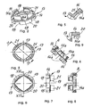
- the fitting has been generally indicated by 1 and has a support body 2 including a shoulder 2A, a female threaded end 3, as illustrated, or a male threaded end, for coupling a part of a heating or sanitary system, not shown, and a pipe holder end 4.
- This pipe holder end 4 can have any suitable contour and, in the illustrated embodiment, houses therein two O-rings 6.
- the number 7 shows a front wall of the shoulder 2A and the number 8 shows an annular rib defining, with the front wall 7A, a latching or locking slot or groove 8A.
- the number 9 shows a metal bushing to be pressed, or pressing bushing, the ends 11, 12 of which are likewise contoured, i.e. they are outward tapering.
- the number 13 shows a metal support ring, preferably made of brass, having two annular collars 14, 16 of different diameters and coupled as a single piece with a circumferential flange wall 17.
- the outer ends of the annular collars 14, 16 have a hook tapering annular contour 14A, 16A.
- Figure 2 shows that both collars 14, 16 have a plurality of substantially U-shaped openings 18, 19, which are outward open. In the shown embodiment, the U-shaped openings 19 of the collar 16 are respectively opposite to a solid region between the adjoining openings 18 of the opposite collar 14 or vice-versa.
- the number 22 shows an insulating gasket, which can be fitted with a clearance on the pipe holder end 4 toward and against said annular lug 8.
- the openings 19 of the collar 16 have a large size allowing to easily and quickly see the position of the end of the plastic pipe 3 to be abutted against the insulating washer 22 bearing on the annular lug 8 (or directly on the annular lug 8 in the case of plastics material single-layer or multiple-layer pipes) before applying the pliers for pressing the bushing 9.
- the larger diameter collar 14 provides a geometric engagement coupling collar for coupling with a corresponding slot 6 formed in the jaws of the pliers P, the end T of the pliers circumferentially covering the openings 19 in the collar 16 in engagement with the shoulder 2A.
- the pliers P has a symmetrical construction, with two slots S to be applied either from a side or the other.
- the letter Z shows two known circumferential pressing ribs, the position of which depend on the positions of the O-rings 6.
- the components 2, 13, 9 can be automatically assembled with a quick sequence of coaxial movements, in which, at first, on the pipe holder end 4 are engaged the insulating washer 22 then the support ring 13 and finally the symmetric bushing 9, wherein, during the feeding of the support ring 13 and bushing 9 to an end of stroke position, a geometric push coupling will be obtained, while providing the above mentioned snap engagements of the support ring 13 on the shoulder 2 and bushing 9 in said support ring 13.
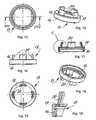
- the support ring 13 has the larger diameter collar 14 in the form of a cylindrical sleeve or liner, i.e. without openings, whereas the smaller collar 16 differentiates from the first embodiment since it has a frustum of cone shape tapering towards the shoulder 2A of the fitting body 2.
- both collars 14, 16 do not have contoured front end portions, but a practically smooth construction.
- the axial locking of the bushing 9 is achieved, preferably during the assembling operation, by circumferentially distributed point deformations 25, in this example four cross-arranged point deformations 25.
- the teeth 20 forming the smaller collar 16 are trapezium shaped. This feature, which can also be used in the first embodiment, allows to better see the end of the fitted plastics pipe 23 and increases the elasticity of the teeth 20.
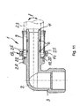
- the inner diameter of the bushing 9 is chosen substantially equal to the outer diameter of the plastic pipe 23, shown with dash-dot lines in Figure 11, thereby providing an interference type of coupling with the pipe 23 which, upon fitting, will be substantially locked on the pipe holder end 4 and, through the bushing 9, in the gap between said bushing 9 and the pipe holder end 4.
- the bushing 9 forms a blocking element for locking the plastics pipe 23 in abutment against the insulating washer 22. Accordingly, a proper abutment of the pipe 23 against the washer 22, as detected before the pressing operation, i.e. before applying the pliers P, is safely maintained even after the application of the pliers and the pressing operation.
- the leg 22A can substantially close from inside the openings 19 of the collar 16. This prevents electrically conductive liquid drops or dirt particles from forming short circuits between the fitting body 2 and metal liner provided in a composite pipe 23. Said L-cross section gasket 22, on the other hand, does not have any supporting function.
- fittings to be fixed to a component of a sanitary, heating or fluid distributing system could also be applied to double fittings, i.e. having a fitting body with two axially opposite pipe holder ends, optionally of different diameters, as well as to T-shaped and the like fittings, without departing from the scope of the invention.
Landscapes
- Engineering & Computer Science (AREA)
- General Engineering & Computer Science (AREA)
- Mechanical Engineering (AREA)
- Mutual Connection Of Rods And Tubes (AREA)
- Forms Removed On Construction Sites Or Auxiliary Members Thereof (AREA)
- Quick-Acting Or Multi-Walled Pipe Joints (AREA)
- Lining Or Joining Of Plastics Or The Like (AREA)
- Branch Pipes, Bends, And The Like (AREA)
Claims (10)
- Raccord pour couplage sous pression, par une passe à mâchoires adaptées, de conduites en matériau plastique, comme des conduites plastiques du type à couche unique, à couches multiples ou composites, ou comportant un revêtement métallique intégré, en particulier pour des systèmes de chauffage, sanitaires et de distribution de fluide, ledit raccord comprenant :caractérisée en ce quea) un corps de raccord avec
une extrémité filetée pour le couplage à une pièce d'un système de chauffage, sanitaire ou de distribution de fluide,une extrémité de retenue de conduite opposée etun épaulement de positionnement médian pour ladite conduite plastique monté sur l'extrémité de retenue de conduite,b) une douille de pression métallique, formant avec ladite extrémité de retenue de conduite une chambre annulaire pour loger dans celle-ci l'extrémité de la conduite plastique à coupler au raccord etc) une bague de support apte à venir en prise, à une extrémité, avec ledit épaulement et à supporter, à l'autre extrémité, ladite douille de pression, où ladite bague de support permet de surveiller visuellement la position de l'extrémité de conduite plastique à la région d'épaulement, avant d'appliquer la pince,i) la bague de support (13) est réalisée en un matériau métallique et comprend deux colliers adjacents (14, 16) de diamètres différents et couplés l'un à l'autre par une paroi de bride radiale annulaire (17),ii) au moins le collier (16) au côté de l'épaulement (2A) présente des ouvertures circonférentielles (19) sensiblement en forme de U ouvertes vers ledit épaulement (2A) et formant entre elles des secteurs dentés (21) ayant au moins des propriétés élastiques limitées,iii) ladite ouverture circonférentielle (19) au côté de l'épaulement (2A) étant formée pour permettre de voir l'extrémité de la conduite plastique (23) à ladite région d'épaulement (2A, 7) pendant que la pince de serrage (P) n'est pas appliquée, tandis que, lorsque ladite pince de serrage (P) est appliquée, c'est-à-dire lors d'une opération de pressage, lesdites ouvertures circonférentielles (19) sont recouvertes par le corps de la pince (P),iv) où une rondelle (22) en un matériau électriquement isolant montée sur ladite extrémité de retenue de conduite (4) et séparant l'extrémité de la conduite plastique (23) de l'épaulement (2A, 7) du raccord (1) est réalisée, etv) ladite douille de pression (9) possède une configuration symétrique, avec des extrémités similaires (11, 12), s'étendant vers l'extérieur et vers le haut. - Raccord selon la revendication 1, caractérisé en ce que les deux colliers (14, 16) formant ladite bague de support (13) possèdent des ouvertures circonférentielles (18, 19) orientées vers l'extérieur d'une forme sensiblement en U.
- Raccord selon la revendication 1, caractérisé en ce que dans ladite bague de support (13), ledit collier (16) côté épaulement (2A) possède une configuration tronconique vers l'extérieur, tandis que ledit collier (14) côté douille de pression (9) a une configuration cylindrique linéaire.
- Raccord selon la revendication 1, caractérisé en ce que lesdites ouvertures circonférentielles (19) comprennent quatre ouvertures agencées en croix, la longueur desdites ouvertures étant de préférence plus grande que la longueur desdites dents (21) formées entre lesdites ouvertures (19).
- Raccord selon la revendication 1, caractérisé en ce que ledit épaulement (2A) présente, sur son côté (7) orienté vers ladite extrémité de retenue de conduite (4) une fente (8A) pour engager dans celle-ci les extrémités desdites dents de support (21) formées sur ledit collier (16) de ladite bague de support (13).
- Raccord selon les revendications 2 et 5, caractérisé en ce que les extrémités desdites dents de support (21) ont un contour en forme de crochet (16A) pour s'engager dans ladite rainure d'épaulement (8A).
- Raccord selon les revendications 1 et 3, caractérisé en ce que ladite douille (9) est verrouillée axialement, mais peut être déplacée dans des limites dans une direction radiale, par des déformations ponctuelles (25) du collier de revêtement cylindrique (14), par exemple quatre déformations en point agencées en croix.
- Raccord selon la revendication 3, caractérisé en ce que les extrémités intérieures des dents (21) du collier tronconique (16) sont d'une construction lisse.
- Raccord selon la revendication 1, caractérisé en ce que les joints toriques (6) engagés dans les rainures de l'extrémité de retenue de conduite (4) font saillie de celle-ci, et en ce que la douille de pression (9) a un diamètre intérieur permettant que ladite conduite plastique (21) soit couplée par ajustement serré à l'extrémité de retenue de conduite (4) en butée contre ledit épaulement (2A, 7).
- Raccord selon la revendication 1 et l'une ou plusieurs des revendications suivantes, caractérisé en ce que ledit raccord comprend, sur les deux côtés d'un épaulement médian, une extrémité de retenue de conduite respective, lesdites extrémités de retenue de conduite étant axialement opposées et ayant, en option, des diamètres différents, ou un corps en forme de T ou analogue.
Applications Claiming Priority (3)
| Application Number | Priority Date | Filing Date | Title |
|---|---|---|---|
| IT2000MI000637A IT1317144B1 (it) | 2000-03-27 | 2000-03-27 | Raccordo per il fissaggio di tubi di materiale sintetico |
| ITMI20000637 | 2000-03-27 | ||
| PCT/EP2001/003421 WO2001073330A2 (fr) | 2000-03-27 | 2001-03-26 | Raccord pour couplage sous pression de conduite en plastique |
Publications (2)
| Publication Number | Publication Date |
|---|---|
| EP1277008A2 EP1277008A2 (fr) | 2003-01-22 |
| EP1277008B1 true EP1277008B1 (fr) | 2005-11-30 |
Family
ID=11444640
Family Applications (1)
| Application Number | Title | Priority Date | Filing Date |
|---|---|---|---|
| EP01927806A Expired - Lifetime EP1277008B1 (fr) | 2000-03-27 | 2001-03-26 | Raccord pour couplage sous pression de conduite en plastique |
Country Status (5)
| Country | Link |
|---|---|
| EP (1) | EP1277008B1 (fr) |
| AT (1) | ATE311568T1 (fr) |
| DE (1) | DE60115413T2 (fr) |
| IT (1) | IT1317144B1 (fr) |
| WO (1) | WO2001073330A2 (fr) |
Cited By (1)
| Publication number | Priority date | Publication date | Assignee | Title |
|---|---|---|---|---|
| RU2746429C2 (ru) * | 2016-11-09 | 2021-04-13 | Пермасвейдж | Соединительное тело, фитинги, гидравлическая система для прохождения жидкости между двумя гидравлическими контурами, соответствующий способ монтажа |
Families Citing this family (10)
| Publication number | Priority date | Publication date | Assignee | Title |
|---|---|---|---|---|
| ES2274953T3 (es) * | 2002-08-07 | 2007-06-01 | Emmeti S.P.A. | Conexion para tubos con funcion de comprobacion. |
| FR2870314B1 (fr) * | 2004-05-14 | 2006-06-23 | Comap Sa | Bague de visualisation du sertissage d'un raccord pour tubes |
| FR2932871A1 (fr) * | 2008-06-23 | 2009-12-25 | Saint Germain & Straub S A | Embout pour raccord de tuyau de canalisation en materiau plastique et utilisation. |
| FR3042579B1 (fr) * | 2015-10-19 | 2017-11-10 | Comap | Dispositif de visualisation de sertissage pour un raccord a sertir |
| US11543065B2 (en) | 2016-09-02 | 2023-01-03 | Zurn Industries, Llc | Extruded cold-expansion compression collar |
| US11541581B2 (en) | 2016-09-02 | 2023-01-03 | Zurn Industries, Llc | Injection molded cold-expansion compression collar |
| US11054076B2 (en) | 2016-11-04 | 2021-07-06 | Zurn Industries, Llc | Reinforcing ring with sleeve |
| KR20230167451A (ko) | 2017-01-05 | 2023-12-08 | 라이프 테크놀로지스 코포레이션 | 커플링 조립체 |
| KR102000018B1 (ko) * | 2017-09-21 | 2019-07-15 | 주식회사 프럼파스트 | 체결파이프 회전방지 록킹구조를 가지는 완전삽입 확인이 용이한 산업용 멀티 레이어 유체배관 클림핑 연결시스템의 플라스틱 이음구조체 시공방법 |
| DE102019216828A1 (de) * | 2019-10-31 | 2021-05-06 | Fränkische Rohrwerke Gebr. Kirchner Gmbh & Co. Kg | Pressfitting |
Family Cites Families (7)
| Publication number | Priority date | Publication date | Assignee | Title |
|---|---|---|---|---|
| US3549180A (en) | 1968-05-16 | 1970-12-22 | Scovill Manufacturing Co | Hose and hose coupling assembly |
| DE4304680C1 (de) | 1993-02-16 | 1994-04-28 | Kirchner Fraenk Rohr | Abdichtende Verbindung von Kunststoff-Metall-Kunststoff-Verbundrohren |
| DE4441373C2 (de) | 1994-11-21 | 1997-12-04 | Kirchner Fraenk Rohr | Rohrverbindung, insbesondere für Rohre mit mindestens einer Kunststoffschicht |
| DE29503019U1 (de) * | 1995-02-23 | 1995-04-06 | Viegener Ii Fa Franz | Abdichtende Verbindung eines Kunststoffrohres mit einem aus Metall gefertigten Anschlußstück |
| AT402095B (de) * | 1995-09-27 | 1997-01-27 | Verbex Produktions Und Vertrie | Verbindungsstück, insbesondere mit gewindeanschluss, zum aufpressen auf das ende eines rohres |
| DE19545361C2 (de) * | 1995-12-05 | 2000-06-29 | Gabo Systemtech Gmbh | Rohrverbindung mit Fitting |
| DE59914701D1 (de) * | 1998-04-17 | 2008-05-08 | Herz Armaturen Gmbh | Leitungssystem |
-
2000
- 2000-03-27 IT IT2000MI000637A patent/IT1317144B1/it active
-
2001
- 2001-03-26 DE DE60115413T patent/DE60115413T2/de not_active Expired - Lifetime
- 2001-03-26 AT AT01927806T patent/ATE311568T1/de not_active IP Right Cessation
- 2001-03-26 WO PCT/EP2001/003421 patent/WO2001073330A2/fr active IP Right Grant
- 2001-03-26 EP EP01927806A patent/EP1277008B1/fr not_active Expired - Lifetime
Cited By (1)
| Publication number | Priority date | Publication date | Assignee | Title |
|---|---|---|---|---|
| RU2746429C2 (ru) * | 2016-11-09 | 2021-04-13 | Пермасвейдж | Соединительное тело, фитинги, гидравлическая система для прохождения жидкости между двумя гидравлическими контурами, соответствующий способ монтажа |
Also Published As
| Publication number | Publication date |
|---|---|
| DE60115413D1 (de) | 2006-01-05 |
| DE60115413T2 (de) | 2006-08-17 |
| WO2001073330A2 (fr) | 2001-10-04 |
| WO2001073330A3 (fr) | 2002-01-03 |
| EP1277008A2 (fr) | 2003-01-22 |
| ITMI20000637A0 (it) | 2000-03-27 |
| ITMI20000637A1 (it) | 2001-09-27 |
| ATE311568T1 (de) | 2005-12-15 |
| IT1317144B1 (it) | 2003-05-27 |
Similar Documents
| Publication | Publication Date | Title |
|---|---|---|
| US11529722B2 (en) | Fluid connector with full insertion assurance cap disconnect tool | |
| US11112045B2 (en) | Fluid connector with full insertion assurance cap with secondary latches | |
| US4725081A (en) | Detachable plug assembly | |
| EP1277008B1 (fr) | Raccord pour couplage sous pression de conduite en plastique | |
| US6302447B1 (en) | Self-locking coupling device | |
| EP2995844B1 (fr) | Joint de tuyau en résine synthétique | |
| EP0753696B1 (fr) | Dispositif d'étanchéité pour raccord de tuyauterie | |
| US6260854B1 (en) | Flat gasket ring | |
| KR0162154B1 (ko) | 2개의 유체관을 연결하기 위한 압입 연결기 | |
| US20020093199A1 (en) | Bayonet quick coupler | |
| CA2073501C (fr) | Dispositif pour raccorder un tuyau flexible a un raccord tubulaire rigide | |
| US6234544B1 (en) | Quick connector with confirmation feature | |
| EP0778437B1 (fr) | Raccord avec verrouillage à ressort | |
| KR20220145404A (ko) | 관 이음매 | |
| JPH09269089A (ja) | 改良連結器 | |
| WO2019009049A1 (fr) | Structure de raccordement pour dispositif à fluide | |
| EP3436730B1 (fr) | Dispositif de raccordement de tuyau à verrouillage à indicateur | |
| US11168820B2 (en) | Assembly of a coupling and a stiff tube and method therefore | |
| US6412826B1 (en) | High pressure quick connector | |
| GB2195411A (en) | Pipe connectors | |
| CZ300441B6 (cs) | Zarízení pro spojování trubek trubkových vedení | |
| EP3301339B1 (fr) | Ensemble comprenant un connecteur d'assemblage par pression et un tube ondulé et kit comprenant cet ensemble et un outil d'assemblage par pression pour son application | |
| US7121595B2 (en) | Device for leaktight coupling of a tube to a threaded tubular nose | |
| EP0729556B1 (fr) | Systeme de couplage avec connecteur rapide | |
| US3710911A (en) | Liquid-tight swivel coupler for electrical conduit |
Legal Events
| Date | Code | Title | Description |
|---|---|---|---|
| PUAI | Public reference made under article 153(3) epc to a published international application that has entered the european phase |
Free format text: ORIGINAL CODE: 0009012 |
|
| 17P | Request for examination filed |
Effective date: 20021023 |
|
| AK | Designated contracting states |
Kind code of ref document: A2 Designated state(s): AT BE CH CY DE DK ES FI FR GB GR IE IT LI LU MC NL PT SE TR |
|
| AX | Request for extension of the european patent |
Free format text: SI |
|
| GRAP | Despatch of communication of intention to grant a patent |
Free format text: ORIGINAL CODE: EPIDOSNIGR1 |
|
| GRAS | Grant fee paid |
Free format text: ORIGINAL CODE: EPIDOSNIGR3 |
|
| GRAA | (expected) grant |
Free format text: ORIGINAL CODE: 0009210 |
|
| AK | Designated contracting states |
Kind code of ref document: B1 Designated state(s): AT BE CH CY DE DK ES FI FR GB GR IE IT LI LU MC NL PT SE TR |
|
| PG25 | Lapsed in a contracting state [announced via postgrant information from national office to epo] |
Ref country code: FI Free format text: LAPSE BECAUSE OF FAILURE TO SUBMIT A TRANSLATION OF THE DESCRIPTION OR TO PAY THE FEE WITHIN THE PRESCRIBED TIME-LIMIT Effective date: 20051130 Ref country code: BE Free format text: LAPSE BECAUSE OF FAILURE TO SUBMIT A TRANSLATION OF THE DESCRIPTION OR TO PAY THE FEE WITHIN THE PRESCRIBED TIME-LIMIT Effective date: 20051130 Ref country code: NL Free format text: LAPSE BECAUSE OF FAILURE TO SUBMIT A TRANSLATION OF THE DESCRIPTION OR TO PAY THE FEE WITHIN THE PRESCRIBED TIME-LIMIT Effective date: 20051130 |
|
| REG | Reference to a national code |
Ref country code: GB Ref legal event code: FG4D Ref country code: CH Ref legal event code: EP |
|
| REG | Reference to a national code |
Ref country code: IE Ref legal event code: FG4D |
|
| REF | Corresponds to: |
Ref document number: 60115413 Country of ref document: DE Date of ref document: 20060105 Kind code of ref document: P |
|
| PG25 | Lapsed in a contracting state [announced via postgrant information from national office to epo] |
Ref country code: GR Free format text: LAPSE BECAUSE OF FAILURE TO SUBMIT A TRANSLATION OF THE DESCRIPTION OR TO PAY THE FEE WITHIN THE PRESCRIBED TIME-LIMIT Effective date: 20060228 Ref country code: DK Free format text: LAPSE BECAUSE OF FAILURE TO SUBMIT A TRANSLATION OF THE DESCRIPTION OR TO PAY THE FEE WITHIN THE PRESCRIBED TIME-LIMIT Effective date: 20060228 Ref country code: SE Free format text: LAPSE BECAUSE OF FAILURE TO SUBMIT A TRANSLATION OF THE DESCRIPTION OR TO PAY THE FEE WITHIN THE PRESCRIBED TIME-LIMIT Effective date: 20060228 |
|
| PG25 | Lapsed in a contracting state [announced via postgrant information from national office to epo] |
Ref country code: ES Free format text: LAPSE BECAUSE OF FAILURE TO SUBMIT A TRANSLATION OF THE DESCRIPTION OR TO PAY THE FEE WITHIN THE PRESCRIBED TIME-LIMIT Effective date: 20060313 |
|
| PG25 | Lapsed in a contracting state [announced via postgrant information from national office to epo] |
Ref country code: GB Free format text: LAPSE BECAUSE OF NON-PAYMENT OF DUE FEES Effective date: 20060326 |
|
| PG25 | Lapsed in a contracting state [announced via postgrant information from national office to epo] |
Ref country code: IE Free format text: LAPSE BECAUSE OF NON-PAYMENT OF DUE FEES Effective date: 20060327 |
|
| PG25 | Lapsed in a contracting state [announced via postgrant information from national office to epo] |
Ref country code: LU Free format text: LAPSE BECAUSE OF NON-PAYMENT OF DUE FEES Effective date: 20060331 Ref country code: MC Free format text: LAPSE BECAUSE OF NON-PAYMENT OF DUE FEES Effective date: 20060331 |
|
| PG25 | Lapsed in a contracting state [announced via postgrant information from national office to epo] |
Ref country code: PT Free format text: LAPSE BECAUSE OF FAILURE TO SUBMIT A TRANSLATION OF THE DESCRIPTION OR TO PAY THE FEE WITHIN THE PRESCRIBED TIME-LIMIT Effective date: 20060502 |
|
| REG | Reference to a national code |
Ref country code: CH Ref legal event code: NV Representative=s name: WERNER FENNER PATENTANWALT |
|
| NLV1 | Nl: lapsed or annulled due to failure to fulfill the requirements of art. 29p and 29m of the patents act | ||
| PLBE | No opposition filed within time limit |
Free format text: ORIGINAL CODE: 0009261 |
|
| STAA | Information on the status of an ep patent application or granted ep patent |
Free format text: STATUS: NO OPPOSITION FILED WITHIN TIME LIMIT |
|
| 26N | No opposition filed |
Effective date: 20060831 |
|
| GBPC | Gb: european patent ceased through non-payment of renewal fee |
Effective date: 20060326 |
|
| REG | Reference to a national code |
Ref country code: IE Ref legal event code: MM4A |
|
| EN | Fr: translation not filed | ||
| PG25 | Lapsed in a contracting state [announced via postgrant information from national office to epo] |
Ref country code: FR Free format text: LAPSE BECAUSE OF FAILURE TO SUBMIT A TRANSLATION OF THE DESCRIPTION OR TO PAY THE FEE WITHIN THE PRESCRIBED TIME-LIMIT Effective date: 20070119 |
|
| PG25 | Lapsed in a contracting state [announced via postgrant information from national office to epo] |
Ref country code: TR Free format text: LAPSE BECAUSE OF FAILURE TO SUBMIT A TRANSLATION OF THE DESCRIPTION OR TO PAY THE FEE WITHIN THE PRESCRIBED TIME-LIMIT Effective date: 20051130 |
|
| PG25 | Lapsed in a contracting state [announced via postgrant information from national office to epo] |
Ref country code: FR Free format text: LAPSE BECAUSE OF FAILURE TO SUBMIT A TRANSLATION OF THE DESCRIPTION OR TO PAY THE FEE WITHIN THE PRESCRIBED TIME-LIMIT Effective date: 20060331 |
|
| PG25 | Lapsed in a contracting state [announced via postgrant information from national office to epo] |
Ref country code: CY Free format text: LAPSE BECAUSE OF FAILURE TO SUBMIT A TRANSLATION OF THE DESCRIPTION OR TO PAY THE FEE WITHIN THE PRESCRIBED TIME-LIMIT Effective date: 20051130 Ref country code: FR Free format text: LAPSE BECAUSE OF FAILURE TO SUBMIT A TRANSLATION OF THE DESCRIPTION OR TO PAY THE FEE WITHIN THE PRESCRIBED TIME-LIMIT Effective date: 20051130 |
|
| PG25 | Lapsed in a contracting state [announced via postgrant information from national office to epo] |
Ref country code: IT Free format text: LAPSE BECAUSE OF NON-PAYMENT OF DUE FEES Effective date: 20080326 |
|
| PGFP | Annual fee paid to national office [announced via postgrant information from national office to epo] |
Ref country code: AT Payment date: 20100331 Year of fee payment: 10 |
|
| PGRI | Patent reinstated in contracting state [announced from national office to epo] |
Ref country code: IT Effective date: 20110101 |
|
| PG25 | Lapsed in a contracting state [announced via postgrant information from national office to epo] |
Ref country code: AT Free format text: LAPSE BECAUSE OF NON-PAYMENT OF DUE FEES Effective date: 20110326 |
|
| PGFP | Annual fee paid to national office [announced via postgrant information from national office to epo] |
Ref country code: CH Payment date: 20180319 Year of fee payment: 18 |
|
| PGFP | Annual fee paid to national office [announced via postgrant information from national office to epo] |
Ref country code: DE Payment date: 20180329 Year of fee payment: 18 |
|
| PGFP | Annual fee paid to national office [announced via postgrant information from national office to epo] |
Ref country code: IT Payment date: 20180330 Year of fee payment: 18 |
|
| REG | Reference to a national code |
Ref country code: DE Ref legal event code: R119 Ref document number: 60115413 Country of ref document: DE |
|
| REG | Reference to a national code |
Ref country code: CH Ref legal event code: PL |
|
| PG25 | Lapsed in a contracting state [announced via postgrant information from national office to epo] |
Ref country code: CH Free format text: LAPSE BECAUSE OF NON-PAYMENT OF DUE FEES Effective date: 20190331 Ref country code: LI Free format text: LAPSE BECAUSE OF NON-PAYMENT OF DUE FEES Effective date: 20190331 Ref country code: DE Free format text: LAPSE BECAUSE OF NON-PAYMENT OF DUE FEES Effective date: 20191001 |
|
| PG25 | Lapsed in a contracting state [announced via postgrant information from national office to epo] |
Ref country code: IT Free format text: LAPSE BECAUSE OF NON-PAYMENT OF DUE FEES Effective date: 20190326 |