EP1276693B1 - Device and process for mixing liquids - Google Patents
Device and process for mixing liquids Download PDFInfo
- Publication number
- EP1276693B1 EP1276693B1 EP01933884A EP01933884A EP1276693B1 EP 1276693 B1 EP1276693 B1 EP 1276693B1 EP 01933884 A EP01933884 A EP 01933884A EP 01933884 A EP01933884 A EP 01933884A EP 1276693 B1 EP1276693 B1 EP 1276693B1
- Authority
- EP
- European Patent Office
- Prior art keywords
- container
- filling head
- diverter
- filling
- component
- Prior art date
- Legal status (The legal status is an assumption and is not a legal conclusion. Google has not performed a legal analysis and makes no representation as to the accuracy of the status listed.)
- Expired - Lifetime
Links
- 238000002156 mixing Methods 0.000 title claims abstract description 22
- 238000000034 method Methods 0.000 title claims description 23
- 230000008569 process Effects 0.000 title claims description 9
- 239000007788 liquid Substances 0.000 title description 4
- 239000012141 concentrate Substances 0.000 claims abstract description 37
- 239000003085 diluting agent Substances 0.000 claims abstract description 33
- 239000003599 detergent Substances 0.000 claims description 9
- 238000004891 communication Methods 0.000 claims description 6
- 239000012530 fluid Substances 0.000 claims description 6
- 235000008504 concentrate Nutrition 0.000 description 27
- 239000000463 material Substances 0.000 description 8
- 238000011109 contamination Methods 0.000 description 6
- 230000009471 action Effects 0.000 description 5
- 239000000203 mixture Substances 0.000 description 5
- 239000006188 syrup Substances 0.000 description 5
- 235000020357 syrup Nutrition 0.000 description 5
- 238000005187 foaming Methods 0.000 description 4
- 230000007246 mechanism Effects 0.000 description 4
- 238000007789 sealing Methods 0.000 description 4
- 230000000694 effects Effects 0.000 description 3
- 238000005429 filling process Methods 0.000 description 3
- 230000002093 peripheral effect Effects 0.000 description 3
- 239000004033 plastic Substances 0.000 description 3
- 229920003023 plastic Polymers 0.000 description 3
- 229920001824 Barex® Polymers 0.000 description 2
- 235000013361 beverage Nutrition 0.000 description 2
- 229920001971 elastomer Polymers 0.000 description 2
- 238000009472 formulation Methods 0.000 description 2
- 235000014666 liquid concentrate Nutrition 0.000 description 2
- 239000012528 membrane Substances 0.000 description 2
- 239000000243 solution Substances 0.000 description 2
- 238000003860 storage Methods 0.000 description 2
- XLYOFNOQVPJJNP-UHFFFAOYSA-N water Substances O XLYOFNOQVPJJNP-UHFFFAOYSA-N 0.000 description 2
- 241001411320 Eriogonum inflatum Species 0.000 description 1
- 239000004677 Nylon Substances 0.000 description 1
- 239000004698 Polyethylene Substances 0.000 description 1
- 239000004743 Polypropylene Substances 0.000 description 1
- 239000000853 adhesive Substances 0.000 description 1
- 230000001070 adhesive effect Effects 0.000 description 1
- 238000013019 agitation Methods 0.000 description 1
- 230000004888 barrier function Effects 0.000 description 1
- 235000014171 carbonated beverage Nutrition 0.000 description 1
- 230000000295 complement effect Effects 0.000 description 1
- 238000004090 dissolution Methods 0.000 description 1
- 230000007613 environmental effect Effects 0.000 description 1
- 238000010101 extrusion blow moulding Methods 0.000 description 1
- 239000004744 fabric Substances 0.000 description 1
- 238000007667 floating Methods 0.000 description 1
- 229920001903 high density polyethylene Polymers 0.000 description 1
- 239000004700 high-density polyethylene Substances 0.000 description 1
- 238000002347 injection Methods 0.000 description 1
- 239000007924 injection Substances 0.000 description 1
- 238000010102 injection blow moulding Methods 0.000 description 1
- 239000000314 lubricant Substances 0.000 description 1
- 238000004519 manufacturing process Methods 0.000 description 1
- 229920001778 nylon Polymers 0.000 description 1
- 239000005020 polyethylene terephthalate Substances 0.000 description 1
- 239000004800 polyvinyl chloride Substances 0.000 description 1
- 238000003825 pressing Methods 0.000 description 1
- 230000009467 reduction Effects 0.000 description 1
- 238000009877 rendering Methods 0.000 description 1
- 230000004044 response Effects 0.000 description 1
- 229920006395 saturated elastomer Polymers 0.000 description 1
Images

Classifications
-
- B—PERFORMING OPERATIONS; TRANSPORTING
- B67—OPENING, CLOSING OR CLEANING BOTTLES, JARS OR SIMILAR CONTAINERS; LIQUID HANDLING
- B67D—DISPENSING, DELIVERING OR TRANSFERRING LIQUIDS, NOT OTHERWISE PROVIDED FOR
- B67D1/00—Apparatus or devices for dispensing beverages on draught
- B67D1/0042—Details of specific parts of the dispensers
- B67D1/0043—Mixing devices for liquids
- B67D1/0044—Mixing devices for liquids for mixing inside the dispensing nozzle
- B67D1/0046—Mixing chambers
- B67D1/005—Mixing chambers with means for converging streams
-
- B—PERFORMING OPERATIONS; TRANSPORTING
- B01—PHYSICAL OR CHEMICAL PROCESSES OR APPARATUS IN GENERAL
- B01F—MIXING, e.g. DISSOLVING, EMULSIFYING OR DISPERSING
- B01F25/00—Flow mixers; Mixers for falling materials, e.g. solid particles
- B01F25/30—Injector mixers
- B01F25/31—Injector mixers in conduits or tubes through which the main component flows
- B01F25/314—Injector mixers in conduits or tubes through which the main component flows wherein additional components are introduced at the circumference of the conduit
- B01F25/3141—Injector mixers in conduits or tubes through which the main component flows wherein additional components are introduced at the circumference of the conduit with additional mixing means other than injector mixers
-
- B—PERFORMING OPERATIONS; TRANSPORTING
- B01—PHYSICAL OR CHEMICAL PROCESSES OR APPARATUS IN GENERAL
- B01F—MIXING, e.g. DISSOLVING, EMULSIFYING OR DISPERSING
- B01F25/00—Flow mixers; Mixers for falling materials, e.g. solid particles
- B01F25/40—Static mixers
- B01F25/42—Static mixers in which the mixing is affected by moving the components jointly in changing directions, e.g. in tubes provided with baffles or obstructions
- B01F25/43—Mixing tubes, e.g. wherein the material is moved in a radial or partly reversed direction
- B01F25/433—Mixing tubes wherein the shape of the tube influences the mixing, e.g. mixing tubes with varying cross-section or provided with inwardly extending profiles
- B01F25/4336—Mixers with a diverging cross-section
-
- B—PERFORMING OPERATIONS; TRANSPORTING
- B01—PHYSICAL OR CHEMICAL PROCESSES OR APPARATUS IN GENERAL
- B01F—MIXING, e.g. DISSOLVING, EMULSIFYING OR DISPERSING
- B01F25/00—Flow mixers; Mixers for falling materials, e.g. solid particles
- B01F25/40—Static mixers
- B01F25/42—Static mixers in which the mixing is affected by moving the components jointly in changing directions, e.g. in tubes provided with baffles or obstructions
- B01F25/43—Mixing tubes, e.g. wherein the material is moved in a radial or partly reversed direction
- B01F25/434—Mixing tubes comprising cylindrical or conical inserts provided with grooves or protrusions
-
- B—PERFORMING OPERATIONS; TRANSPORTING
- B67—OPENING, CLOSING OR CLEANING BOTTLES, JARS OR SIMILAR CONTAINERS; LIQUID HANDLING
- B67C—CLEANING, FILLING WITH LIQUIDS OR SEMILIQUIDS, OR EMPTYING, OF BOTTLES, JARS, CANS, CASKS, BARRELS, OR SIMILAR CONTAINERS, NOT OTHERWISE PROVIDED FOR; FUNNELS
- B67C3/00—Bottling liquids or semiliquids; Filling jars or cans with liquids or semiliquids using bottling or like apparatus; Filling casks or barrels with liquids or semiliquids
- B67C3/02—Bottling liquids or semiliquids; Filling jars or cans with liquids or semiliquids using bottling or like apparatus
- B67C3/22—Details
- B67C3/28—Flow-control devices, e.g. using valves
- B67C3/281—Profiled valve bodies for smoothing the flow at the outlet of the filling nozzle
-
- B—PERFORMING OPERATIONS; TRANSPORTING
- B67—OPENING, CLOSING OR CLEANING BOTTLES, JARS OR SIMILAR CONTAINERS; LIQUID HANDLING
- B67D—DISPENSING, DELIVERING OR TRANSFERRING LIQUIDS, NOT OTHERWISE PROVIDED FOR
- B67D1/00—Apparatus or devices for dispensing beverages on draught
- B67D1/0042—Details of specific parts of the dispensers
- B67D1/0043—Mixing devices for liquids
- B67D1/0044—Mixing devices for liquids for mixing inside the dispensing nozzle
-
- B—PERFORMING OPERATIONS; TRANSPORTING
- B67—OPENING, CLOSING OR CLEANING BOTTLES, JARS OR SIMILAR CONTAINERS; LIQUID HANDLING
- B67D—DISPENSING, DELIVERING OR TRANSFERRING LIQUIDS, NOT OTHERWISE PROVIDED FOR
- B67D1/00—Apparatus or devices for dispensing beverages on draught
- B67D1/08—Details
- B67D1/0829—Keg connection means
- B67D1/0831—Keg connection means combined with valves
- B67D1/0835—Keg connection means combined with valves with one valve
-
- B—PERFORMING OPERATIONS; TRANSPORTING
- B01—PHYSICAL OR CHEMICAL PROCESSES OR APPARATUS IN GENERAL
- B01F—MIXING, e.g. DISSOLVING, EMULSIFYING OR DISPERSING
- B01F25/00—Flow mixers; Mixers for falling materials, e.g. solid particles
- B01F2025/91—Direction of flow or arrangement of feed and discharge openings
- B01F2025/913—Vortex flow, i.e. flow spiraling in a tangential direction and moving in an axial direction
Definitions
- the present invention relates to a device and process for product reconstitution.
- Yet another existing method entails the dissolution of a concentrate by active mixing of a concentrate dosed into a diluent and agitation by using a mechanical device such as a paddle or a rotating rod.
- Filling machines may dispense a wide variety of products from the same machine.
- Such machines may include production line filling machines and vending systems which are designed to fill containers at sites located in, for example, retail outlets, offices and other workplaces.
- linking system in the present application, is meant a filling machine that dispenses product in response to one or more selections that are input into the machine by the user.
- a system may be operated by coin, token, card, or other suitable means.
- a concentrate diluent are dosed into a storage container located in said machine through a common nozzle or aperture prior to dispensing into a storage container located in said machine.
- a common nozzle or aperture prior to dispensing into a storage container located in said machine.
- the design of filling machines avoids the contamination issue by isolating the concentrates and filling them directly into the container prior to adding the diluent. This method is effective in avoiding contamination but does not allow the effective mixing and reconstitution of the concentrate.
- the alternative method of dispensing concentrates into the container and adding the diluent does not provide a consistently well mixed product and limits the range of concentrate formulations possible by such a method to those formulations that have an inherently high solubility.
- Methods that attempt to improve reconstitution through the introduction of turbulence or shear in the concentrate and/or the diluent can induce foaming in the product which reduces product fill rates.
- US 3,966,091 describes a carbonated beverage dispenser which includes a valve body defining a carbonated liquid inlet, a syrup inlet, a bore and an elongated syrup stem disposed within the bore. Carbonated liquid flows over a diffuser member and is then post-mixed with syrup. There is no mention in US 3,966,091 of reconstitution of detergent products.
- US 5,285,815 describes a post-mix beverage dispensing valve for mixing carbonated water with syrup. The carbonated water does not mix with the syrup until it has reached the bottom of a nozzle central portion. There is no mention in US 5,285,815 of reconstitution of detergent products.
- FR 1,180,592 describes a bottle stopper and a filling process for filling a bottle with a liquid saturated with gas under pressure. There is no disclosure in FR 1,180,592 of the mixing of one or more concentrates and diluents to form a reconstituted detergent product.
- a device for the mixing of one or more concentrates and diluents to form a reconstituted product at an interface between a container and a filling head as the container is filled using said filling head comprising the combination of:
- a device for the mixing of one or more concentrates and diluents to form a reconstituted product at an interface between a container and a filling head as the container is filled using said filling head comprising the combination of:
- the present invention provides a process for the mixing of one or more concentrates and diluents to form a reconstituted product at an interface between a container and a filling head as the container is filled using a device according to one of claims 1 or 2, wherein said process comprises:-
- product passes through the chamber between said component and the fill aperture.
- interface between a container and a filling head is meant a chamber formed by the filling head and the optional diverter therein and/or the chamber formed by the fill aperture and the component or diverter therein.
- the component located in the fill aperture of said container may be designed so that the chamber between the fill aperture and said component remains closed until connected to the filling head component.
- said component may be designed so that the chamber may be opened manually by the user, in addition to automatic opening when in connection with the filling head.
- the nature of the component is not limited in the present invention, provided that the chamber between the fill aperture and said component may open and re-close by some function of the filling process, by the action of the filling machine, or a mechanism thereof, or by the inherent nature of the fill aperture, and that said component fits together with the filling head nozzle so as to provide a direct path from the filling head to the interior of the container.
- the design of the filling head for a filling machine which may provide a single filling point, simplifies the filling machine design and therefore reduces filling machine cost.
- the design also serves to eliminate contamination problems arising from previous product mixtures, by providing discrete concentrate and diluent inlet tubes, and by ensuring mixing of concentrates and diluents does not occur in the filling machine, but at the interface between a container and a filling head upon dispense.
- the design of the diverter and surrounding chamber facilitates high speed filling into the container and further serves to allow low turbulence mixing upon filling, thereby preventing foaming.
- the diverter may be torpedo-shaped.
- the diverter may be of a square or rectangular cross-section, as seen in the horizontal plane and a taper that can exhibit a hyperbolic or exponential curve or cross-section, depending on the reconstitution requirements of the product.
- the position of the diverter relative to the surrounding chamber may be varied about any axis, in order to regulate the flow of concentrate or diluent (in terms of product volume over time, or velocity across the associated surfaces) in order to effect reliable reconstitution, to effect speed of fill, or to effect reduction in foaming.
- the diverter may be a free-floating element trapped within the mixing chamber. On the action of filling, the diverter may be positioned centrally within said chamber by the action of the flow of concentrate and diluent.
- An interrupted ring may be added to a point from the base of the mixing diverter, which may conveniently be one-third from the base of said diverter, in order to produce a stand-off device to prevent the initial flow of product pressing the diverter against the exit to the mixing chamber, and thereby accidentally effecting a seal.
- grooves may be included in the interior of the base of the mixing chamber to allow the initial flow of product to pass beneath,the diverter, and to initiate the positioning of the diverter at the centre of the mixing chamber.
- said container in relation to the container to be filled, said container comprises a fill aperture, said fill aperture comprising therein a diverter, said diverter being such that the difference between the diameter of the diverter and that of the surrounding aperture is such that the cross-sectional area of the aperture section gradually increases in the direction of flow of the filling head component, so as to pass the product thereby reconstituted to the interior of the container.
- the diverter may be contained entirely within the container as an injection moulded or fabricated component, and the fill apertures communicating with the filling head may be one or more simple apertures. It will be appreciated that in this embodiment the diverter shape may be modified to comprise a torpedo-shaped upper section and a lower section whose shape is not limited.
- the fill aperture will preferably open and re-close by some function of the filling process, by the action of the filling machine, or a mechanism thereof. It will be further appreciated that in the case where the fill aperture also acts as the dispense aperture, that said fill aperture may be designed to be opened manually by the user, in addition to automatic opening when in connection with the filling head.
- the filling machine is a vending system.
- the nature of the containers are not limited. However, for both economic and environmental reasons, it is highly desirable to employ reusable containers, that is to say where the container is returned to the point of sale or dispense to be refilled once emptied of its contents. This process may be repeated many times, and the container may be refilled with contents different to those previously in the container.
- Such containers are available in a wide variety of shapes and forms. They may be assembled from a wide variety of components, and may be manufactured from a wide variety of materials.
- Said containers may be manufactured from a plastics material.
- said container may be manufactured by any conventional process for the forming of plastics material.
- Suitable plastics include materials such as for example PET, PP, PE, HDPE, PVC and barrier laminates such as PET/NYLON/PET and PP/BAREX/PP.
- BAREX is a trade mark of BP Amoco plc.
- Said containers may be manufactured by an extrusion or injection blow-moulding process.
- Containers generally have a bottom wall, peripheral side walls, and an upper portion comprising one or more fill and/or dispense apertures.
- the terms “bottom”, “side” and “upper” are used to identify those positions of the container when it is in its normal orientation in use.
- Said peripheral side walls may be of a collapsible nature. It will be appreciated by one skilled in the art, that for convenience, said bottom wall and/or upper portion may be also be of a collapsible nature.
- the upper portion may be an integral part of the container, or it may be securely sealed to the peripheral side walls by any technique commonly used in the art. Suitable techniques include heat sealing, ultrasonic sealing and the use of adhesives.
- the containers may comprise a collapsible bag or sachet.
- the container may comprise any number, combination and orientation of fill and/or dispense apertures that meet the needs of the product, its intended use or its method of use.
- the containers may include any dispensing, dosing or application feature or device providing the means to dispense the product in a wide variety of ways.
- the containers may include provision for manual or powered dispensing.
- the container may include any further device or mechanism for filling known in the art.
- the containers may comprise an exhaust arrangement or the container may be evacuated prior to being filled.
- dispense aperture closure is not limited and may be of any kind commonly used in the art.
- the location of the fill aperture is not limited. However, preferably the fill aperture will be centrally located on the container.
- centrally located in the present specification is meant that the location of the fill aperture or apertures provides a symmetry, thereby allowing the container to be filled independently of the orientation of the container when placed in the filling machine.
- filling head in the present invention, is meant the nozzle of the filling machine which dispenses the product. It will be appreciated that the filling machine may comprise multiple filling heads.
- the fill aperture of the container may be in fluid communication with one or more tubes which extend to the bottom of said container, thereby allowing bottom filling.
- Suitable tubes may be of any kind commonly used in the art, and in a preferred embodiment will be flattened membrane tubes.
- bottom filling is meant that the tip of the filling head contacts, or is very closely adjacent to the bottom of the container, that is to say incoming product is not discharged into the headspace but into the body of product present inside said container. Bottom filling eliminates air for products susceptible to foaming, for example, detergents.
- headspace in the present invention, is meant the space between the upper level (head) of the product stored in the container, and the limit of the cavity of said container.
- said tubes may be formed from the fabric of said bag or sachet.
- Said tubes may be arranged in a variety of configurations and with a variety of apertures to allow filling of materials with varying viscosities and other characteristics such as particulates.
- Containers may be conveniently used to store and transport a wide variety of materials such as foodstuffs, beverages, household products such as detergents, and automotive products such as lubricants.
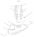
- An upper portion 1 of a container (not shown) comprises a fill aperture 2, said fill aperture 2 comprising a component 3, which is capable of forming an interface with a filling head component 4 of a filling machine (not shown).
- Said upper portion 1 further comprises a dispense aperture 5 covered by a lid 6.
- Fill aperture 2 is centrally located within said upper portion 1.
- Said filling head component 4 comprises a plurality of inlet tubes 7, which may be used to disperse a concentrate material, and an inlet tube 8, which may be used to dispense a diluent material.
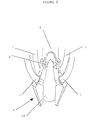
- said inlet tubes 7 and 8 are in fluid communication with a central chamber 9.
- Said chamber 9 contains therein a torpedo-shaped diverter 10, said diverter 10 being such that the difference between the diameter of the diverter and that of the surrounding chamber gradually increases the dimension of the nozzle section that contacts incoming product.
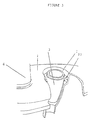
- said component 3 is located in said upper portion 1 of the container (not shown) and is surrounded by a rubber sealing flange 11.
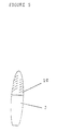
- Figure 5 shows an elevational view of the interface between said torpedo-shaped diverter 10 and said component 3 of the container, said component 3 being tapered in the direction of product flow.
- the interface between said torpedo-shaped diverter 10 and said component 3 provides a surface over which product may flow.
- the diverter 10 comprises flutes which serve to produce a vortex and turbulence in order to aid mixing.
- said diverter 10 Whilst said component 3 is located in said upper portion 1 of a container, said diverter 10 may either be located in said filling head component 4 or be located in the upper portion 1 of the container. In the latter arrangement, the diverter 10 and component 3 therefore form upper and lower sections of a diverter located in said upper portion 1 of the container.
- the container may be provided with an optional membrane tube 12 which facilitates bottom filling of said container.
Landscapes
- Chemical & Material Sciences (AREA)
- Chemical Kinetics & Catalysis (AREA)
- Dispersion Chemistry (AREA)
- Basic Packing Technique (AREA)
- Filling Of Jars Or Cans And Processes For Cleaning And Sealing Jars (AREA)
- Processing And Handling Of Plastics And Other Materials For Molding In General (AREA)
- Supply Of Fluid Materials To The Packaging Location (AREA)
- Accessories For Mixers (AREA)
Abstract
Description
- The present invention relates to a device and process for product reconstitution.
- Methods of product reconstitution are known in the art wherein liquid concentrates are mixed with a diluent by means of an aspirator containing a venturi. In this method, the venturi draws liquid concentrate into contact with the diluent stream, thereby mixing concentrate and diluent together. In such a method, any number of concentrates may be envisaged.
- Other methods exist in the art, wherein concentrates are dosed into a container and a diluent added.
- Yet another existing method entails the dissolution of a concentrate by active mixing of a concentrate dosed into a diluent and agitation by using a mechanical device such as a paddle or a rotating rod.
- Filling machines may dispense a wide variety of products from the same machine. Such machines may include production line filling machines and vending systems which are designed to fill containers at sites located in, for example, retail outlets, offices and other workplaces.
- By "vending system" in the present application, is meant a filling machine that dispenses product in response to one or more selections that are input into the machine by the user. Such a system may be operated by coin, token, card, or other suitable means.
- In another method of product reconstitution, typically used in filling machines, a concentrate diluent are dosed into a storage container located in said machine through a common nozzle or aperture prior to dispensing into a storage container located in said machine. In such a method there is the potential for contamination of the product with residual product from the previous vend.
- In a situation where multiple vends of a variety of concentrate combinations are required from the same machine, the potential for contamination is increased.
- Typically, the design of filling machines, such as vending machines, avoids the contamination issue by isolating the concentrates and filling them directly into the container prior to adding the diluent. This method is effective in avoiding contamination but does not allow the effective mixing and reconstitution of the concentrate.
- The mixing of concentrates with diluents and/or the addition of customised combinations of concentrates adds complexity and the potential for contamination in filling machines.
- The alternative method of dispensing concentrates into the container and adding the diluent does not provide a consistently well mixed product and limits the range of concentrate formulations possible by such a method to those formulations that have an inherently high solubility.
- Methods that attempt to improve reconstitution through the introduction of turbulence or shear in the concentrate and/or the diluent can induce foaming in the product which reduces product fill rates.
- Solutions to the problems noted above result in filling nozzles of greater complexity and greater cost than the dispense mechanisms typically used in filling machines such as vending systems, thereby rendering solutions to the problems impractical on cost grounds.
- US 3,966,091 describes a carbonated beverage dispenser which includes a valve body defining a carbonated liquid inlet, a syrup inlet, a bore and an elongated syrup stem disposed within the bore. Carbonated liquid flows over a diffuser member and is then post-mixed with syrup. There is no mention in US 3,966,091 of reconstitution of detergent products.
- US 5,285,815 describes a post-mix beverage dispensing valve for mixing carbonated water with syrup. The carbonated water does not mix with the syrup until it has reached the bottom of a nozzle central portion. There is no mention in US 5,285,815 of reconstitution of detergent products.
- FR 1,180,592 describes a bottle stopper and a filling process for filling a bottle with a liquid saturated with gas under pressure. There is no disclosure in FR 1,180,592 of the mixing of one or more concentrates and diluents to form a reconstituted detergent product.
- According to the present invention there is provided a device for the mixing of one or more concentrates and diluents to form a reconstituted product at an interface between a container and a filling head as the container is filled using said filling head, comprising the combination of:-
- (i) a filling head component, comprising one or more concentrate and diluent inlet tubes, said inlet tubes being in fluid communication with a central chamber, said chamber comprising therein a diverter, said diverter being such that the difference between the diameter of the diverter and that of the surrounding chamber is such that the cross-sectional area of the flow passage in the nozzle section gradually increases in the direction of flow of the filling head component; and
- (ii) a component located in a fill aperture of the container, said components being engageable with one another so as to provide a direct path from said filling head to the interior of the container, wherein the interface between said diverter and said component provides a surface over which the components of the product flow and wherein the reconstituted product is a detergent.
-
- According to the present invention, there is further provided a device for the mixing of one or more concentrates and diluents to form a reconstituted product at an interface between a container and a filling head as the container is filled using said filling head, comprising the combination of:-
- (i) a filling head component comprising one or more concentrate and diluent inlet tubes, said inlet tubes being in fluid communication with a fill aperture of the container; and
- (ii) a diverter located in the fill aperture of said container, said diverter comprising an upper section and a lower section, said diverter being such that the difference between the diameter of the diverter and that of the surrounding aperture is such that the cross-sectional area of the flow passage in the aperture section gradually increases in the direction of flow of the filling head component, said filling head component and said fill aperture being engageable with one another so as to provide a direct path from said filling head to the interior of the container, wherein the interface between the upper section and the lower section of the diverter provides a surface over which the components of the product flow, and wherein the reconstituted product is a detergent.
-
- In a further aspect, the present invention provides a process for the mixing of one or more concentrates and diluents to form a reconstituted product at an interface between a container and a filling head as the container is filled using a device according to one of
claims - (i) engaging said filling head and a fill aperture of said container so as to provide a direct path from said filling machine to the interior of the container;
- (ii) passing one or more concentrates and diluents to said filling head component, so as to mix said concentrate(s) and diluent(s) at the interface between the container and the filling head; and
- (iii) passing the product thereby mixed at said interface to the interior of the container.
-
- As will be described below, product passes through the chamber between said component and the fill aperture.
- By "interface between a container and a filling head", is meant a chamber formed by the filling head and the optional diverter therein and/or the chamber formed by the fill aperture and the component or diverter therein.
- The component located in the fill aperture of said container, may be designed so that the chamber between the fill aperture and said component remains closed until connected to the filling head component. However, it will be appreciated that in the case where the fill aperture also acts as the dispense aperture, said component may be designed so that the chamber may be opened manually by the user, in addition to automatic opening when in connection with the filling head.
- The nature of the component is not limited in the present invention, provided that the chamber between the fill aperture and said component may open and re-close by some function of the filling process, by the action of the filling machine, or a mechanism thereof, or by the inherent nature of the fill aperture, and that said component fits together with the filling head nozzle so as to provide a direct path from the filling head to the interior of the container.
- The design of the filling head for a filling machine, which may provide a single filling point, simplifies the filling machine design and therefore reduces filling machine cost.
- The design also serves to eliminate contamination problems arising from previous product mixtures, by providing discrete concentrate and diluent inlet tubes, and by ensuring mixing of concentrates and diluents does not occur in the filling machine, but at the interface between a container and a filling head upon dispense.
- The design of the diverter and surrounding chamber facilitates high speed filling into the container and further serves to allow low turbulence mixing upon filling, thereby preventing foaming.
- By placing a component in the container, which is engageable with the filling head component, it is possible to reduce the functionality required in the filling machine, that is to say said component may be moulded and introduced into said container at low cost, compared with the introduction of a similar component into the filling head of the filling machine.
- The diverter may be torpedo-shaped. The diverter may be of a square or rectangular cross-section, as seen in the horizontal plane and a taper that can exhibit a hyperbolic or exponential curve or cross-section, depending on the reconstitution requirements of the product.
- The position of the diverter relative to the surrounding chamber may be varied about any axis, in order to regulate the flow of concentrate or diluent (in terms of product volume over time, or velocity across the associated surfaces) in order to effect reliable reconstitution, to effect speed of fill, or to effect reduction in foaming.
- The diverter may be a free-floating element trapped within the mixing chamber. On the action of filling, the diverter may be positioned centrally within said chamber by the action of the flow of concentrate and diluent.
- An interrupted ring may be added to a point from the base of the mixing diverter, which may conveniently be one-third from the base of said diverter, in order to produce a stand-off device to prevent the initial flow of product pressing the diverter against the exit to the mixing chamber, and thereby accidentally effecting a seal.
- As an alternative to this detail, grooves may be included in the interior of the base of the mixing chamber to allow the initial flow of product to pass beneath,the diverter, and to initiate the positioning of the diverter at the centre of the mixing chamber.
- In a further aspect, in relation to the container to be filled, said container comprises a fill aperture, said fill aperture comprising therein a diverter, said diverter being such that the difference between the diameter of the diverter and that of the surrounding aperture is such that the cross-sectional area of the aperture section gradually increases in the direction of flow of the filling head component, so as to pass the product thereby reconstituted to the interior of the container.
- Thus, the diverter may be contained entirely within the container as an injection moulded or fabricated component, and the fill apertures communicating with the filling head may be one or more simple apertures. It will be appreciated that in this embodiment the diverter shape may be modified to comprise a torpedo-shaped upper section and a lower section whose shape is not limited.
- As the engineering detail and complexity are located in the mass-produced container, and not in the filling machine, it is possible to reduce implementation cost.
- The position of said diverter and associated fill and dispense apertures is not limited. Thus, it will be appreciated by one skilled in the art that said features may be present in the side walls of the container, as an alternative to being located in the upper portion of said container.
- It will be appreciated by one skilled in the art that the fill aperture will preferably open and re-close by some function of the filling process, by the action of the filling machine, or a mechanism thereof. It will be further appreciated that in the case where the fill aperture also acts as the dispense aperture, that said fill aperture may be designed to be opened manually by the user, in addition to automatic opening when in connection with the filling head.
- In a preferred embodiment of the present invention, the filling machine is a vending system.
- The nature of the containers are not limited. However, for both economic and environmental reasons, it is highly desirable to employ reusable containers, that is to say where the container is returned to the point of sale or dispense to be refilled once emptied of its contents. This process may be repeated many times, and the container may be refilled with contents different to those previously in the container.
- Such containers are available in a wide variety of shapes and forms. They may be assembled from a wide variety of components, and may be manufactured from a wide variety of materials.
- Said containers may be manufactured from a plastics material. As such, said container may be manufactured by any conventional process for the forming of plastics material. Suitable plastics include materials such as for example PET, PP, PE, HDPE, PVC and barrier laminates such as PET/NYLON/PET and PP/BAREX/PP. BAREX is a trade mark of BP Amoco plc.
- Said containers may be manufactured by an extrusion or injection blow-moulding process.
- Containers generally have a bottom wall, peripheral side walls, and an upper portion comprising one or more fill and/or dispense apertures. The terms "bottom", "side" and "upper" are used to identify those positions of the container when it is in its normal orientation in use.
- Said peripheral side walls may be of a collapsible nature. It will be appreciated by one skilled in the art, that for convenience, said bottom wall and/or upper portion may be also be of a collapsible nature.
- The upper portion may be an integral part of the container, or it may be securely sealed to the peripheral side walls by any technique commonly used in the art. Suitable techniques include heat sealing, ultrasonic sealing and the use of adhesives.
- The containers may comprise a collapsible bag or sachet.
- The container may comprise any number, combination and orientation of fill and/or dispense apertures that meet the needs of the product, its intended use or its method of use.
- The containers may include any dispensing, dosing or application feature or device providing the means to dispense the product in a wide variety of ways.
- The containers may include provision for manual or powered dispensing.
- The container may include any further device or mechanism for filling known in the art.
- The containers may comprise an exhaust arrangement or the container may be evacuated prior to being filled.
- The nature of the dispense aperture closure is not limited and may be of any kind commonly used in the art.
- The location of the fill aperture is not limited. However, preferably the fill aperture will be centrally located on the container.
- By "centrally located" in the present specification is meant that the location of the fill aperture or apertures provides a symmetry, thereby allowing the container to be filled independently of the orientation of the container when placed in the filling machine.
- By "filling head" in the present invention, is meant the nozzle of the filling machine which dispenses the product. It will be appreciated that the filling machine may comprise multiple filling heads.
- The fill aperture of the container may be in fluid communication with one or more tubes which extend to the bottom of said container, thereby allowing bottom filling. Suitable tubes may be of any kind commonly used in the art, and in a preferred embodiment will be flattened membrane tubes.
- By "bottom filling" is meant that the tip of the filling head contacts, or is very closely adjacent to the bottom of the container, that is to say incoming product is not discharged into the headspace but into the body of product present inside said container. Bottom filling eliminates air for products susceptible to foaming, for example, detergents.
- By "headspace" in the present invention, is meant the space between the upper level (head) of the product stored in the container, and the limit of the cavity of said container.
- In the case of said container being a bag or sachet, said tubes may be formed from the fabric of said bag or sachet.
- Said tubes may be arranged in a variety of configurations and with a variety of apertures to allow filling of materials with varying viscosities and other characteristics such as particulates.
- Containers may be conveniently used to store and transport a wide variety of materials such as foodstuffs, beverages, household products such as detergents, and automotive products such as lubricants.
- The present invention will now be described by way of example, with reference to the accompanying drawings, in which:-
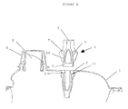
- Figure 1 is a fragmentary perspective view of a filling head component of a filling machine and an upper portion of a container comprising a component, shown prior to engagement of said components for allowing said container to be filled;
- Figure 2 is a fragmentary cutaway perspective view of said filling head component of a filling machine;
- Figure 3 is a fragmentary cutaway perspective view of said component of a container;
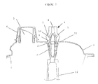
- Figure 4 is a fragmentary cutaway perspective view of an interface between said filling head component of a filling machine and said component of the container, showing said components in engagement for allowing said container to be filled;.
- Figure 5 is an elevational view of a diverter and said component of the container;
- Figure 6 is a cross-sectional elevation through said filling head component of a filling machine and said upper portion of a container comprising a complementary component, taken along the line X-X in Figure 1; and
- Figure 7 is a cross-sectional elevation through said interface between said filling head component of the filling machine and said component of the container, taken along the line Y-Y in Figure 4.
-
- An
upper portion 1 of a container (not shown) comprises afill aperture 2, saidfill aperture 2 comprising acomponent 3, which is capable of forming an interface with a fillinghead component 4 of a filling machine (not shown). Saidupper portion 1 further comprises a dispenseaperture 5 covered by alid 6.Fill aperture 2 is centrally located within saidupper portion 1. Said fillinghead component 4 comprises a plurality ofinlet tubes 7, which may be used to disperse a concentrate material, and aninlet tube 8, which may be used to dispense a diluent material. - As shown in detail in Figure 2 said
inlet tubes central chamber 9. Saidchamber 9 contains therein a torpedo-shapeddiverter 10, said diverter 10 being such that the difference between the diameter of the diverter and that of the surrounding chamber gradually increases the dimension of the nozzle section that contacts incoming product. - As shown in detail in Figure 3, said
component 3 is located in saidupper portion 1 of the container (not shown) and is surrounded by arubber sealing flange 11. - The action of inserting said filling
head component 4 into saidfill aperture 2 of said container displaces saidrubber sealing flange 11, so as to provide a direct route from said filling machine to the interior of said container. - Figure 5 shows an elevational view of the interface between said torpedo-shaped
diverter 10 and saidcomponent 3 of the container, saidcomponent 3 being tapered in the direction of product flow. The interface between said torpedo-shapeddiverter 10 and saidcomponent 3 provides a surface over which product may flow. Thediverter 10 comprises flutes which serve to produce a vortex and turbulence in order to aid mixing. - Whilst said
component 3 is located in saidupper portion 1 of a container, said diverter 10 may either be located in said fillinghead component 4 or be located in theupper portion 1 of the container. In the latter arrangement, thediverter 10 andcomponent 3 therefore form upper and lower sections of a diverter located in saidupper portion 1 of the container. - The container may be provided with an
optional membrane tube 12 which facilitates bottom filling of said container.
Claims (4)
- A device for the mixing of one or more concentrates and diluents to form a reconstituted product at an interface between a container and a filling head as the container is filled using said filling head, comprising the combination of:-(i) a filling head component (4), comprising one or more concentrate and diluent inlet tubes (7; 8), said inlet tubes (7; 8) being in fluid communication with a central chamber (9), said chamber (9) comprising therein a diverter (10), said diverter (10) being such that the difference between the diameter of the diverter (10) and that of the surrounding chamber (9) is such that the cross-sectional area of the flow passage in the nozzle section gradually increases in the direction of flow of the filling head component (4); and(ii) a component (3) located in a fill aperture (2) of the container,
said components being engageable with one another so as to provide a direct path from said filling head to the interior of the container, wherein the interface between said diverter (10) and said component (3) provides a surface over which the components of the product flow and wherein the reconstituted product is a detergent. - A device for the mixing of one or more concentrates and diluents to form a reconstituted product at an interface between a container and a filling head as the container is filled using said filling head, comprising the combination of:-wherein the interface between the upper section (10) and the lower section (3) of the diverter provides a surface over which the components of the product flow, and wherein the reconstituted product is a detergent.(i) a filling head component (4) comprising one or more concentrate and diluent inlet tubes (7; 8), said inlet tubes (7; 8) being in fluid communication with a fill aperture (2) of the container; and(ii) a diverter located in the fill aperture (2) of said container, said diverter comprising an upper section (10) and a lower section (3), said diverter being such that the difference between the diameter of the diverter and that of the surrounding aperture (2) is such that the cross-sectional area of the flow passage in the aperture section gradually increases in the direction of flow of the filling head component (4), said filling head component (4) and said fill aperture (2) being engageable with one another so as to provide a direct path from said filling head to the interior of the container,
- A process for the mixing of one or more concentrates and diluents to form a reconstituted product at an interface between a container and a filling head as the container is filled using a device according to one of claims 1 or 2, wherein said process comprises:-(i) engaging said filling head and a fill aperture (2) of said container so as to provide a direct path from said filling machine to the interior of the container;(ii) passing one or more concentrates and diluents to said filling head component (4), so as to mix said concentrate(s) and diluent(s) at the interface between the container and the filling head; and(iii) passing the product thereby mixed at said interface to the interior of the container.
- A process according to Claim 3, wherein the filling machine is a vending machine.
Priority Applications (1)
| Application Number | Priority Date | Filing Date | Title |
|---|---|---|---|
| EP01933884A EP1276693B1 (en) | 2000-04-25 | 2001-04-24 | Device and process for mixing liquids |
Applications Claiming Priority (4)
| Application Number | Priority Date | Filing Date | Title |
|---|---|---|---|
| EP00303430 | 2000-04-25 | ||
| EP00303430 | 2000-04-25 | ||
| EP01933884A EP1276693B1 (en) | 2000-04-25 | 2001-04-24 | Device and process for mixing liquids |
| PCT/EP2001/004667 WO2001081236A1 (en) | 2000-04-25 | 2001-04-24 | Device and process for mixing liquids |
Publications (2)
| Publication Number | Publication Date |
|---|---|
| EP1276693A1 EP1276693A1 (en) | 2003-01-22 |
| EP1276693B1 true EP1276693B1 (en) | 2005-06-22 |
Family
ID=8172936
Family Applications (1)
| Application Number | Title | Priority Date | Filing Date |
|---|---|---|---|
| EP01933884A Expired - Lifetime EP1276693B1 (en) | 2000-04-25 | 2001-04-24 | Device and process for mixing liquids |
Country Status (11)
| Country | Link |
|---|---|
| US (1) | US6598631B2 (en) |
| EP (1) | EP1276693B1 (en) |
| CN (1) | CN100408469C (en) |
| AR (1) | AR033523A1 (en) |
| AT (1) | ATE298312T1 (en) |
| AU (1) | AU2001260246A1 (en) |
| BR (1) | BR0110347B1 (en) |
| DE (1) | DE60111627T2 (en) |
| ES (1) | ES2240455T3 (en) |
| MX (1) | MXPA02010509A (en) |
| WO (1) | WO2001081236A1 (en) |
Families Citing this family (7)
| Publication number | Priority date | Publication date | Assignee | Title |
|---|---|---|---|---|
| EP1277181A2 (en) * | 2000-04-25 | 2003-01-22 | Shell Internationale Researchmaatschappij B.V. | Process for the customisation of consumer products |
| AU2001258368A1 (en) | 2000-04-25 | 2001-11-07 | Shell Internationale Research Maatschappij B.V. | Process and machine for mixing liquids |
| NL1029124C2 (en) * | 2005-05-25 | 2006-11-28 | Friesland Brands Bv | Dispenser system with gas injection. |
| DE102007028005B4 (en) * | 2007-06-14 | 2011-06-01 | Sig Technology Ag | Apparatus and method for the metered filling of containers, in particular cardboard / plastic composite packaging |
| CN105263850A (en) * | 2013-06-12 | 2016-01-20 | 雀巢产品技术援助有限公司 | Mixing nozzle |
| WO2022051389A1 (en) * | 2020-09-01 | 2022-03-10 | Hydration Labs, Inc. | Single nozzle beverage dispensing |
| DE102020129102A1 (en) | 2020-11-04 | 2022-05-05 | Krones Aktiengesellschaft | Filling element and device for filling a container with a filling product |
Family Cites Families (48)
| Publication number | Priority date | Publication date | Assignee | Title |
|---|---|---|---|---|
| FR1180592A (en) * | 1957-08-05 | 1959-06-05 | Filling and capping of receptacles and in particular those intended to contain liquids saturated with gas under pressure | |
| US3167210A (en) | 1963-04-30 | 1965-01-26 | Greig Bros Cooperage Corp | Device for securing the filler neck of a container liner to the container |
| US3802470A (en) | 1966-12-05 | 1974-04-09 | C Coleman | Composite container and method of handling fluent materials |
| GB1464280A (en) | 1974-07-24 | 1977-02-09 | Alticosalian G H | Perfume dispenser |
| US3938564A (en) * | 1975-01-06 | 1976-02-17 | Kaiser Aerospace And Electronics Corporation | Quick-release fuel coupling for racing cars |
| US3966091A (en) * | 1975-04-11 | 1976-06-29 | Eaton Corporation | Carbonated beverage dispenser having diffuser assembly |
| AU505044B2 (en) | 1975-12-01 | 1979-11-08 | Flex Pack Service and Supplies Pty Ltd | Liquid fill apparatus |
| AT358982B (en) | 1976-04-12 | 1980-10-10 | Schoeller Lebensmittel | CONTAINER FOR PASTOESE SUBSTANCES |
| US4330066A (en) | 1980-11-21 | 1982-05-18 | Robert Berliner | Receptacle with collapsible internal container |
| US4340153A (en) | 1980-11-28 | 1982-07-20 | Spivey David L | Method and apparatus for medication dispensing |
| US4598840A (en) | 1983-10-11 | 1986-07-08 | Burg Donald E | Snap-in cartridge diluter |
| EP0212201A1 (en) | 1985-07-24 | 1987-03-04 | Ingko GmbH Industrieanlagenbau | Apparatus and method for the vacuum-filling of containers, in particular of flexible bags |
| GB2188906A (en) | 1986-04-10 | 1987-10-14 | Otting Int Inc | Method and apparatus for metering and mixing liquid dyes |
| CH670434A5 (en) | 1986-09-17 | 1989-06-15 | Createchnic Dev Ag | |
| US4934567A (en) | 1987-07-20 | 1990-06-19 | Pepsico | Hybrid beverage mixing and dispensing system |
| EP0358053B1 (en) | 1988-09-08 | 1995-07-19 | Sotralentz S.A. | Container assembly for the transport and storage of liquid or powdery products |
| US4929818A (en) | 1988-11-15 | 1990-05-29 | Rainbarrel Corporation | Method and apparatus for vending a containerized product on multiple occasions following at least one refill of the container with the product |
| DE3922779A1 (en) | 1989-07-11 | 1991-01-17 | Sieger Plastic Gmbh | Bag filling appliance on stopper or filler pipe - consists of suction device with valve cone and vale hole, with sealing sleeve and lockable valve |
| US5203474A (en) * | 1990-06-16 | 1993-04-20 | Alco Standard Corporation | Beverage dispensing nozzle |
| US5758571A (en) | 1990-08-06 | 1998-06-02 | Kateman Family Limited Partnership | Method and apparatus for producing and dispensing aerated or blended fluid products |
| DE4031534A1 (en) | 1990-10-05 | 1992-04-09 | Alfill Getraenketechnik | DEVICE FOR PRODUCING BEVERAGES |
| DE4104978A1 (en) | 1991-02-19 | 1992-08-20 | Willich Daemmstoffe Und Zubeho | CONTAINER WITH INLINER |
| CA2051139C (en) | 1991-02-25 | 1995-10-17 | Dwight Ellis Nichols | Liquid transport drum with removable liner |
| US5955132A (en) | 1991-05-24 | 1999-09-21 | Campbell Soup Company | Method for adding flavor materials to beverages |
| EP0528394B1 (en) | 1991-08-20 | 1995-11-22 | Gerhard Haubenwallner | Packaging system |
| US5285815A (en) * | 1991-11-21 | 1994-02-15 | The Cornelius Company | Beverage dispensing valve having quick disconnect mounting |
| DE4313049C2 (en) | 1993-04-21 | 1996-05-15 | Michael L Hoeffgen | Shipping container |
| JPH07175868A (en) | 1993-10-15 | 1995-07-14 | Internatl Business Mach Corp <Ibm> | Method and system for outputting digital information to a medium |
| US5474111A (en) | 1993-10-22 | 1995-12-12 | Degussa Corporation | Fine particle handling |
| AU2316995A (en) | 1994-04-29 | 1995-11-29 | Chris J Grant | Double orifice container |
| US5584327A (en) | 1994-07-06 | 1996-12-17 | Ecolab Inc. | Method and apparatus for storing and dispensing chemical solutions |
| DE4439914C2 (en) | 1994-11-08 | 2002-06-06 | Eltec Mueller Gmbh & Co Kg | bottle |
| US5568828A (en) * | 1994-11-30 | 1996-10-29 | Stant Manufacturing Inc. | Fuel-delivery control system |
| US5516007A (en) | 1994-12-12 | 1996-05-14 | Larson; Donna M. | Dispenser |
| US5685435A (en) | 1995-05-08 | 1997-11-11 | Mars Incorporated | Method and apparatus for automatic bulk vending |
| US5766665A (en) | 1995-05-26 | 1998-06-16 | Archibald Bros. Fine Beverages, Inc. | Method of preparing a multi-flavored comestible shake |
| GB9512210D0 (en) | 1995-06-15 | 1995-08-16 | Reading Graeme J | Liquid dispensing apparatus |
| EP0851791A1 (en) | 1995-07-11 | 1998-07-08 | AG-CHEM EQUIPMENT CO., Inc. | Comprehensive product delivery system |
| NL1001664C2 (en) | 1995-11-16 | 1997-05-21 | Air Delight Holding B V | Automatic vending machine for personal care products. |
| DE19607255A1 (en) | 1996-02-26 | 1997-08-28 | Peter Weckerle | Filling and transport logistics method for paint store |
| US5878798A (en) * | 1997-02-28 | 1999-03-09 | Eastman Kodak Company | Valve system |
| US5996316A (en) | 1997-04-25 | 1999-12-07 | The Coca-Cola Company | System and method for order packing |
| JP3287791B2 (en) | 1997-07-30 | 2002-06-04 | キヤノン株式会社 | Liquid filling method and liquid filling device for liquid container having liquid container |
| DE19813842A1 (en) | 1998-03-23 | 1999-09-30 | Martin Fischer | Information carrying chip card for accompanying transport container in transport process |
| NL1009654C2 (en) * | 1998-07-15 | 2000-01-19 | Heineken Tech Services | Valve assembly for a beverage container, container for beverage and method for filling and emptying a beverage container. |
| AT406259B (en) | 1998-09-30 | 2000-03-27 | Hubert Schneller | BEVERAGE DISPENSER |
| US6250348B1 (en) * | 1999-01-29 | 2001-06-26 | J. C. Carter Company, Inc. | Refueling nozzle |
| DE29913528U1 (en) | 1999-08-03 | 1999-12-02 | Spittel, Wolfgang, 34132 Kassel | After-round filling machine for e.g. Washing lotions, cream, washing powder, fabric softener, bathing agent, cleaning agent, vinegar, oils, mustard etc. |
-
2001
- 2001-04-24 EP EP01933884A patent/EP1276693B1/en not_active Expired - Lifetime
- 2001-04-24 AT AT01933884T patent/ATE298312T1/en not_active IP Right Cessation
- 2001-04-24 MX MXPA02010509A patent/MXPA02010509A/en active IP Right Grant
- 2001-04-24 ES ES01933884T patent/ES2240455T3/en not_active Expired - Lifetime
- 2001-04-24 AU AU2001260246A patent/AU2001260246A1/en not_active Abandoned
- 2001-04-24 WO PCT/EP2001/004667 patent/WO2001081236A1/en not_active Ceased
- 2001-04-24 BR BRPI0110347-4A patent/BR0110347B1/en not_active IP Right Cessation
- 2001-04-24 CN CNB018085199A patent/CN100408469C/en not_active Expired - Fee Related
- 2001-04-24 DE DE60111627T patent/DE60111627T2/en not_active Expired - Lifetime
- 2001-04-25 US US09/843,428 patent/US6598631B2/en not_active Expired - Fee Related
- 2001-04-25 AR ARP010101909A patent/AR033523A1/en unknown
Also Published As
| Publication number | Publication date |
|---|---|
| AR033523A1 (en) | 2003-12-26 |
| US20020066496A1 (en) | 2002-06-06 |
| DE60111627T2 (en) | 2006-05-18 |
| AU2001260246A1 (en) | 2001-11-07 |
| ATE298312T1 (en) | 2005-07-15 |
| BR0110347B1 (en) | 2010-11-16 |
| US6598631B2 (en) | 2003-07-29 |
| DE60111627D1 (en) | 2005-07-28 |
| CN100408469C (en) | 2008-08-06 |
| CN1426373A (en) | 2003-06-25 |
| EP1276693A1 (en) | 2003-01-22 |
| WO2001081236A1 (en) | 2001-11-01 |
| BR0110347A (en) | 2004-06-22 |
| MXPA02010509A (en) | 2003-05-14 |
| ES2240455T3 (en) | 2005-10-16 |
Similar Documents
| Publication | Publication Date | Title |
|---|---|---|
| US11001794B2 (en) | Perfect pour drink mixer | |
| US4984717A (en) | Refillable pressurized beverage container | |
| EP1153881B1 (en) | Multiple-compartment container with tap | |
| EP0246052A1 (en) | Improvements relating to beverage dispensers | |
| US6615880B2 (en) | Process and machine for product mixing | |
| JPS62271891A (en) | Post-mixing drink distributor, nozzle and concentrate supplyassembly | |
| EP0451259A1 (en) | Five-gallon plastic syrup container | |
| US20080314930A1 (en) | Liquid container valve system | |
| RU2381174C1 (en) | Device for hand dispensing of foamy and/or carbonated beverages | |
| US11242236B2 (en) | Perfect pour drink mixer | |
| US12017192B1 (en) | Carbonation mixing nozzles | |
| EP2162385B1 (en) | Closure for beverage container and method for closing an opening of a container | |
| US6209757B1 (en) | Squeezable mixing and dispensing container having removable attachable supply vessels | |
| EP2792615A1 (en) | Pouch with metering handle for dispensing flowable products | |
| US11627838B1 (en) | Perfect pour drink mixer | |
| US6598631B2 (en) | Device and process for product reconstitution | |
| GB2160847A (en) | Tapping device for postmixed drinks | |
| WO2005102868A1 (en) | Membrane activated carbonated beverage dispenser | |
| NL2014993B1 (en) | Single-use container for a single portion substance. | |
| WO1999029586A1 (en) | Injector usable in both erected and inverted state | |
| WO2009131489A1 (en) | Mechanism for attaching a plastic bottle neck to a pouring channel of a device for hand pouring foaming and/or carbonated beverages | |
| CN105764835B (en) | Beverage dispensing system with disposable container | |
| EP0421992A1 (en) | BOTTLE FILLING ARRANGEMENT. | |
| GB2369609A (en) | A Dispensing Container with a Secondary Chamber for Addition of Concentrate | |
| US1088261A (en) | Liquid-dispensing apparatus. |
Legal Events
| Date | Code | Title | Description |
|---|---|---|---|
| PUAI | Public reference made under article 153(3) epc to a published international application that has entered the european phase |
Free format text: ORIGINAL CODE: 0009012 |
|
| 17P | Request for examination filed |
Effective date: 20021016 |
|
| AK | Designated contracting states |
Kind code of ref document: A1 Designated state(s): AT BE CH CY DE DK ES FI FR GB GR IE IT LI LU MC NL PT SE TR |
|
| AX | Request for extension of the european patent |
Free format text: AL;LT;LV;MK;RO;SI |
|
| 17Q | First examination report despatched |
Effective date: 20030210 |
|
| GRAP | Despatch of communication of intention to grant a patent |
Free format text: ORIGINAL CODE: EPIDOSNIGR1 |
|
| GRAS | Grant fee paid |
Free format text: ORIGINAL CODE: EPIDOSNIGR3 |
|
| GRAA | (expected) grant |
Free format text: ORIGINAL CODE: 0009210 |
|
| AK | Designated contracting states |
Kind code of ref document: B1 Designated state(s): AT BE CH CY DE DK ES FI FR GB GR IE IT LI LU MC NL PT SE TR |
|
| PG25 | Lapsed in a contracting state [announced via postgrant information from national office to epo] |
Ref country code: FI Free format text: LAPSE BECAUSE OF FAILURE TO SUBMIT A TRANSLATION OF THE DESCRIPTION OR TO PAY THE FEE WITHIN THE PRESCRIBED TIME-LIMIT Effective date: 20050622 Ref country code: TR Free format text: LAPSE BECAUSE OF FAILURE TO SUBMIT A TRANSLATION OF THE DESCRIPTION OR TO PAY THE FEE WITHIN THE PRESCRIBED TIME-LIMIT Effective date: 20050622 Ref country code: AT Free format text: LAPSE BECAUSE OF FAILURE TO SUBMIT A TRANSLATION OF THE DESCRIPTION OR TO PAY THE FEE WITHIN THE PRESCRIBED TIME-LIMIT Effective date: 20050622 Ref country code: LI Free format text: LAPSE BECAUSE OF FAILURE TO SUBMIT A TRANSLATION OF THE DESCRIPTION OR TO PAY THE FEE WITHIN THE PRESCRIBED TIME-LIMIT Effective date: 20050622 Ref country code: CH Free format text: LAPSE BECAUSE OF FAILURE TO SUBMIT A TRANSLATION OF THE DESCRIPTION OR TO PAY THE FEE WITHIN THE PRESCRIBED TIME-LIMIT Effective date: 20050622 |
|
| REG | Reference to a national code |
Ref country code: GB Ref legal event code: FG4D |
|
| REG | Reference to a national code |
Ref country code: CH Ref legal event code: EP |
|
| REG | Reference to a national code |
Ref country code: IE Ref legal event code: FG4D |
|
| REF | Corresponds to: |
Ref document number: 60111627 Country of ref document: DE Date of ref document: 20050728 Kind code of ref document: P |
|
| PG25 | Lapsed in a contracting state [announced via postgrant information from national office to epo] |
Ref country code: DK Free format text: LAPSE BECAUSE OF FAILURE TO SUBMIT A TRANSLATION OF THE DESCRIPTION OR TO PAY THE FEE WITHIN THE PRESCRIBED TIME-LIMIT Effective date: 20050922 Ref country code: GR Free format text: LAPSE BECAUSE OF FAILURE TO SUBMIT A TRANSLATION OF THE DESCRIPTION OR TO PAY THE FEE WITHIN THE PRESCRIBED TIME-LIMIT Effective date: 20050922 Ref country code: SE Free format text: LAPSE BECAUSE OF FAILURE TO SUBMIT A TRANSLATION OF THE DESCRIPTION OR TO PAY THE FEE WITHIN THE PRESCRIBED TIME-LIMIT Effective date: 20050922 |
|
| REG | Reference to a national code |
Ref country code: ES Ref legal event code: FG2A Ref document number: 2240455 Country of ref document: ES Kind code of ref document: T3 |
|
| PG25 | Lapsed in a contracting state [announced via postgrant information from national office to epo] |
Ref country code: PT Free format text: LAPSE BECAUSE OF FAILURE TO SUBMIT A TRANSLATION OF THE DESCRIPTION OR TO PAY THE FEE WITHIN THE PRESCRIBED TIME-LIMIT Effective date: 20051129 |
|
| REG | Reference to a national code |
Ref country code: CH Ref legal event code: PL |
|
| ET | Fr: translation filed | ||
| PG25 | Lapsed in a contracting state [announced via postgrant information from national office to epo] |
Ref country code: IE Free format text: LAPSE BECAUSE OF NON-PAYMENT OF DUE FEES Effective date: 20060424 |
|
| PG25 | Lapsed in a contracting state [announced via postgrant information from national office to epo] |
Ref country code: MC Free format text: LAPSE BECAUSE OF NON-PAYMENT OF DUE FEES Effective date: 20060430 |
|
| PLBE | No opposition filed within time limit |
Free format text: ORIGINAL CODE: 0009261 |
|
| STAA | Information on the status of an ep patent application or granted ep patent |
Free format text: STATUS: NO OPPOSITION FILED WITHIN TIME LIMIT |
|
| 26N | No opposition filed |
Effective date: 20060323 |
|
| REG | Reference to a national code |
Ref country code: IE Ref legal event code: MM4A |
|
| PG25 | Lapsed in a contracting state [announced via postgrant information from national office to epo] |
Ref country code: LU Free format text: LAPSE BECAUSE OF NON-PAYMENT OF DUE FEES Effective date: 20060424 |
|
| PG25 | Lapsed in a contracting state [announced via postgrant information from national office to epo] |
Ref country code: CY Free format text: LAPSE BECAUSE OF FAILURE TO SUBMIT A TRANSLATION OF THE DESCRIPTION OR TO PAY THE FEE WITHIN THE PRESCRIBED TIME-LIMIT Effective date: 20050622 |
|
| PGFP | Annual fee paid to national office [announced via postgrant information from national office to epo] |
Ref country code: FR Payment date: 20100311 Year of fee payment: 10 |
|
| PGFP | Annual fee paid to national office [announced via postgrant information from national office to epo] |
Ref country code: GB Payment date: 20100329 Year of fee payment: 10 |
|
| PGFP | Annual fee paid to national office [announced via postgrant information from national office to epo] |
Ref country code: ES Payment date: 20100426 Year of fee payment: 10 |
|
| PGFP | Annual fee paid to national office [announced via postgrant information from national office to epo] |
Ref country code: NL Payment date: 20100421 Year of fee payment: 10 Ref country code: IT Payment date: 20100426 Year of fee payment: 10 Ref country code: DE Payment date: 20100506 Year of fee payment: 10 |
|
| PGFP | Annual fee paid to national office [announced via postgrant information from national office to epo] |
Ref country code: BE Payment date: 20100511 Year of fee payment: 10 |
|
| BERE | Be: lapsed |
Owner name: *SHELL INTERNATIONALE RESEARCH MAATSCHAPPIJ B.V. Effective date: 20110430 |
|
| REG | Reference to a national code |
Ref country code: NL Ref legal event code: V1 Effective date: 20111101 |
|
| GBPC | Gb: european patent ceased through non-payment of renewal fee |
Effective date: 20110424 |
|
| REG | Reference to a national code |
Ref country code: FR Ref legal event code: ST Effective date: 20111230 |
|
| PG25 | Lapsed in a contracting state [announced via postgrant information from national office to epo] |
Ref country code: DE Free format text: LAPSE BECAUSE OF NON-PAYMENT OF DUE FEES Effective date: 20111101 Ref country code: NL Free format text: LAPSE BECAUSE OF NON-PAYMENT OF DUE FEES Effective date: 20111101 Ref country code: BE Free format text: LAPSE BECAUSE OF NON-PAYMENT OF DUE FEES Effective date: 20110430 Ref country code: FR Free format text: LAPSE BECAUSE OF NON-PAYMENT OF DUE FEES Effective date: 20110502 |
|
| PG25 | Lapsed in a contracting state [announced via postgrant information from national office to epo] |
Ref country code: GB Free format text: LAPSE BECAUSE OF NON-PAYMENT OF DUE FEES Effective date: 20110424 Ref country code: IT Free format text: LAPSE BECAUSE OF NON-PAYMENT OF DUE FEES Effective date: 20110424 |
|
| REG | Reference to a national code |
Ref country code: DE Ref legal event code: R119 Ref document number: 60111627 Country of ref document: DE Effective date: 20111101 |
|
| REG | Reference to a national code |
Ref country code: ES Ref legal event code: FD2A Effective date: 20120604 |
|
| PG25 | Lapsed in a contracting state [announced via postgrant information from national office to epo] |
Ref country code: ES Free format text: LAPSE BECAUSE OF NON-PAYMENT OF DUE FEES Effective date: 20110425 |