EP1276686B1 - Improved device for automatic centring on belt conveyors - Google Patents
Improved device for automatic centring on belt conveyors Download PDFInfo
- Publication number
- EP1276686B1 EP1276686B1 EP01921467A EP01921467A EP1276686B1 EP 1276686 B1 EP1276686 B1 EP 1276686B1 EP 01921467 A EP01921467 A EP 01921467A EP 01921467 A EP01921467 A EP 01921467A EP 1276686 B1 EP1276686 B1 EP 1276686B1
- Authority
- EP
- European Patent Office
- Prior art keywords
- rollers
- central
- conveyor
- axles
- rocker arm
- Prior art date
- Legal status (The legal status is an assumption and is not a legal conclusion. Google has not performed a legal analysis and makes no representation as to the accuracy of the status listed.)
- Expired - Lifetime
Links
- 238000003780 insertion Methods 0.000 claims description 4
- 230000037431 insertion Effects 0.000 claims description 4
- 230000000295 complement effect Effects 0.000 claims description 2
- 230000000284 resting effect Effects 0.000 claims 1
- 238000006073 displacement reaction Methods 0.000 abstract description 3
- 230000008859 change Effects 0.000 description 3
- 230000006872 improvement Effects 0.000 description 3
- 230000032258 transport Effects 0.000 description 3
- 230000008901 benefit Effects 0.000 description 2
- 230000006866 deterioration Effects 0.000 description 2
- 238000004806 packaging method and process Methods 0.000 description 2
- 230000008439 repair process Effects 0.000 description 2
- 230000003750 conditioning effect Effects 0.000 description 1
- 238000011065 in-situ storage Methods 0.000 description 1
- 238000004519 manufacturing process Methods 0.000 description 1
- 238000012856 packing Methods 0.000 description 1
- 230000035515 penetration Effects 0.000 description 1
- 230000009467 reduction Effects 0.000 description 1
- 238000003860 storage Methods 0.000 description 1
Images


Classifications
-
- B—PERFORMING OPERATIONS; TRANSPORTING
- B65—CONVEYING; PACKING; STORING; HANDLING THIN OR FILAMENTARY MATERIAL
- B65G—TRANSPORT OR STORAGE DEVICES, e.g. CONVEYORS FOR LOADING OR TIPPING, SHOP CONVEYOR SYSTEMS OR PNEUMATIC TUBE CONVEYORS
- B65G39/00—Rollers, e.g. drive rollers, or arrangements thereof incorporated in roller-ways or other types of mechanical conveyors
- B65G39/10—Arrangements of rollers
- B65G39/12—Arrangements of rollers mounted on framework
- B65G39/16—Arrangements of rollers mounted on framework for aligning belts or chains
-
- B—PERFORMING OPERATIONS; TRANSPORTING
- B65—CONVEYING; PACKING; STORING; HANDLING THIN OR FILAMENTARY MATERIAL
- B65G—TRANSPORT OR STORAGE DEVICES, e.g. CONVEYORS FOR LOADING OR TIPPING, SHOP CONVEYOR SYSTEMS OR PNEUMATIC TUBE CONVEYORS
- B65G39/00—Rollers, e.g. drive rollers, or arrangements thereof incorporated in roller-ways or other types of mechanical conveyors
- B65G39/02—Adaptations of individual rollers and supports therefor
- B65G39/04—Adaptations of individual rollers and supports therefor the rollers comprising a number of roller forming elements mounted on a single axle
Definitions
- the invention relates to a device according to the preamble of claim 1, to the technical sector of material handling equipment and continuous transport of materials by belt conveyors, and more particularly conveyor belts dug in the trough and supported by flexible rollers Flexible.
- the centering device automatic conveyor belt conveyor is supported by two rows of flexible rollers (4) having a single central fixing (9) and providing a positive pinch angle, which recalls the trough banding, having a dynamic and stable equilibrium on the axis of the conveyor.
- the single central mounting (9) which is located lower than the attachment points external (5) and common to each pair of said flexible rollers (4), is movable, and is imposed when its altitude varies with the load, a curved trajectory extending in the direction of the longitudinal path of the band by the rotation around a fixed axis (12) of the tilting lever (10) which carries the single central fixation and mobile, so as to reduce the pinch angle according to the load transported.
- the trajectory of the central fixation rotating around the fixed axis is set from way that the pinch is canceled out for the maximum value of the transported load.
- a conveyor implementing the automatic centering devices aforementioned thus uses several garlands arranged in alignment on the path to consider to ensure the transportation and handling of the load.
- the central fasteners (9) of several sets of flexible supports are connected together by means of their respective levers to a cable for setting voltage.
- the fixed axis (12) of each of said levers is connected to a bracket (6) secured to said cable disposed along longitudinal axis (13), of the conveyor which is in tension, between a set screw (15) and tension return means (16), themselves integral with the chassis of the conveyor.
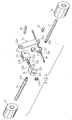
- the single central fixation (9) described in EP-B-504 036 includes, in one piece, a bent shaft (11) V on which are reported fixed way two rollers (4).
- This unique central fixation whose altitude varies according to the load transported, supports the rocking lever (10) rotating about the fixed axis (12), allowing adjustment of the empty pinch angle and the reduction of this angle of pinching as the load increases.
- the angle formed between the bent shaft (11) and the horizontal axis is constant, whatever the curvature of the whole formed by the single central piece (9) and the two rows of flexible rollers (4).
- This single central piece forces the assembly of the two rollers on the bent axis thus forming an integral assembly of the axis, which makes the lever indestructible tilting, and forces the removal of the entire central single piece if one of the elements only is deteriorated.
- the device comprises the features of claim 1.
- the central fixing is referenced by (9) by analogy with the description of the patent EP-B-504 036. It constitutes a single central piece but which, according to the invention, is consisting of several distinct elements, removable from each other and making it possible to meet the objectives desired and aimed at in the invention.
- These distinct elements successively comprise two rollers (20) mounted free rotation on their axes (21) independent V-oriented, means (22) of central connection of the axes according to a given angulation, a fastening means (23) integral with the connecting means (22) of the axes, said attachment means (23) ensuring the receiving and articulation of a rocking lever (24) itself subject to a leg fastening (25) fixedly mounted on the tensioning cable (26).
- the axes (21) of said rollers (20) have profiles linkages (21a-21b) complementary tenons / mortises or equivalent, and likely to constitute a male and a female assembly, the connection being obtained by an axis of link (27) or equivalent crossing the aforementioned central link means (22), or the like link mode.
- the central connecting means (22) has the configuration of a U-shaped stirrup, whose wings (22a-22b) are arranged with openings (22c) allowing the passage and introduction of the connecting pin (27) into the end profile (21a-21b) roller support pins (20), a nut (27a) ensuring the holding of the assembly.
- the attachment means (23) of the rocking lever (24) is configured as a U-shaped screed or other equivalent configuration that can be rendered dismountable relative to the above-mentioned stirrup (22) in the following manner.
- the outer bottom face (23a) of said yoke (23) is capable of coming into bearing on the outer face (22d) of one of the wings of the stirrup (22).
- the bottom face (23a) of the clevis likely to have an opening (23b) allows the passage of the axis of connecting (27) and retaining axles (21) roller supports (20), bolting (27a) being disposed at the end of said male pin to ensure the locking of the assembly.
- the clevis shape (23) is capable of presenting on its wings (23b) the openings (23c) for insertion of a connecting member (28) therethrough the upper end of the rocking lever.
- This connecting means is of the screw-nut type or equivalent.
- rocking lever (24) is thus mounted free with respect to the aforementioned axis (28) to its end (24a) and can be disassembled. It is then sufficient to remove any means of locking that would be associated on the link axis concerning him, type pin or other.
- the other end (24b) of the lever (24) tilting is articulated on the leg fastener (25) attached to the tensioner cable.
- This bracket is of the type of described in the aforementioned EP patent. It comprises two plates (25a-25b) joined between they by a means of connection and allowing insertion into the interior volume as well defines a tension cable (26).
- a locking screw (31) or equivalent provides the connection the lower end of the rocking lever with the fastening lug (25).
- the link can to be preferably removable.
- the cable is likely to receive as previously several sets of central fixation of the aforementioned type with the elements of tension and elastic return as indicated previously.
- This provision is particularly advantageous in that it responds to different needs originally identified. Due to the free assembly of the two rollers higher than their connecting axis, it allows a variation of the angles ⁇ 1 and ⁇ 2 formed by said axes of the rollers with the horizontal axis of the assembly and formed and this, depending on the deformation of the curvature of the garland with the piece center for fixing the flexible rollers during variations in the amplitude of the fastening single plant generated by the variation of the loads transported also in function of the radius of curvature of the half-circumference induced by the variation of widths of the bands used.
- This arrangement also makes it possible to regulate the spacing between the skirts of the rolls composing the center piece and reduce this gap in load avoiding thus the penetration of the strip between the two skirts of the rollers.
- the stirrup component will therefore follow the altitude variations of the fixation single central thus formed in this movement causing the lever (23) of the lever tilting lever (24) and the tilting lever will be imposed when the height of the workpiece varies with the transported load, a curved path extending in the direction of the longitudinal trajectory of the band around a fixed axis of the rocking lever, of to reduce the pinch angle when the transported load increases.
- the curved trajectory of the single central piece is adjusted so that the pinch is canceled when the maximum value of the load transported is obtained.
- the invention thus makes it possible to respond very satisfactorily to the problems posed initially.
- it is easy to disassemble and proceed with the change. This operation can be performed by anyone, the main thing being then to adjust the pinch angles.
- This improvement according to the invention applies both to the upper band belt conveyor only for the return strand.
- FIGS. 8 and 9 show the same arrangement with respect to the strands return with the same components, thus undeniably standardization of the elements composing the central fixation of the invention as well for the upper band than for the return strand.
Abstract
Description
L'invention concerne un dispositif selon le préambule de la revendication 1, au secteur technique du matériel de manutention et de transport en continu de matériaux par convoyeurs à bandes, et plus particulièrement des convoyeurs à bandes creusées en auge et supportées par des rouleaux souples flexibles.The invention relates to a device according to the preamble of claim 1, to the technical sector of material handling equipment and continuous transport of materials by belt conveyors, and more particularly conveyor belts dug in the trough and supported by flexible rollers Flexible.
Le demandeur est titulaire du brevet européen EP-B-504 036, qui vise un dispositif de centrage automatique sur convoyeur à bandes du type précité, et qui est commercialisé sous licence d'une manière satisfaisante selon un développement régulier qui valide et justifie les choix techniques indiqués dans le brevet européen précité.The applicant is the proprietor of the European patent EP-B-504 036, which automatic centering on conveyor belt of the aforementioned type, and which is marketed licensed in a satisfactory manner according to a steady development that validates and justifies the technical choices indicated in the aforementioned European patent.
Pour faciliter la compréhension de l'invention dans le perfectionnement apporté, on fait référence plus spécifiquement à l'art antérieur représentée figures 1, 2 et 3 des dessins.To facilitate understanding of the invention in the improvement provided, reference is made more specifically to the prior art shown in FIGS. 1, 2 and 3 drawings.
Plus particulièrement, selon le brevet européen précité, le dispositif de centrage automatique du convoyeur à bandes transporteuses souples, est supporté par deux rangées de rouleaux flexibles (4) comportant une fixation centrale (9) unique et assurant un angle de pincement positif, qui rappelle la bande mise en forme d'auge, ayant un équilibre dynamique et stable sur l'axe du transporteur.More particularly, according to the aforementioned European patent, the centering device automatic conveyor belt conveyor is supported by two rows of flexible rollers (4) having a single central fixing (9) and providing a positive pinch angle, which recalls the trough banding, having a dynamic and stable equilibrium on the axis of the conveyor.
La fixation centrale unique (9) qui est située plus bas que les points de fixation extérieurs (5) et commune à chaque couple desdits rouleaux flexibles (4), est mobile, et se voit imposée lorsque son altitude varie avec la charge, une trajectoire courbe s'étendant en direction de la trajectoire longitudinale de la bande par la rotation autour d'un axe fixe (12) du levier basculant (10) qui porte la fixation centrale unique et mobile, de façon à réduire l'angle de pincement en fonction de la charge transportée.The single central mounting (9) which is located lower than the attachment points external (5) and common to each pair of said flexible rollers (4), is movable, and is imposed when its altitude varies with the load, a curved trajectory extending in the direction of the longitudinal path of the band by the rotation around a fixed axis (12) of the tilting lever (10) which carries the single central fixation and mobile, so as to reduce the pinch angle according to the load transported.
La trajectoire de la fixation centrale tournant autour de l'axe fixe est réglée de façon que le pincement s'annule pour la valeur maximale de la charge transportée.The trajectory of the central fixation rotating around the fixed axis is set from way that the pinch is canceled out for the maximum value of the transported load.
Un convoyeur mettant en oeuvre les dispositifs de centrage automatiques précités, utilise ainsi plusieurs guirlandes disposées en alignement sur le trajet à considérer pour assurer le transport et la manutention de la charge. A conveyor implementing the automatic centering devices aforementioned, thus uses several garlands arranged in alignment on the path to consider to ensure the transportation and handling of the load.
A cet effet, les fixations centrales (9) de plusieurs ensembles de supports souples sont reliées entre elles par le biais de leurs leviers respectifs à un câble de mise en tension. L'axe fixe (12) de chacun desdits leviers est reliée à une patte d'attache (6) solidarisée audit câble disposé selon axe longitudinal (13), du convoyeur qui est mis en tension, entre une vis de réglage (15) et des moyens de rappel de tension (16), eux-mêmes solidaires du châssis du convoyeur.For this purpose, the central fasteners (9) of several sets of flexible supports are connected together by means of their respective levers to a cable for setting voltage. The fixed axis (12) of each of said levers is connected to a bracket (6) secured to said cable disposed along longitudinal axis (13), of the conveyor which is in tension, between a set screw (15) and tension return means (16), themselves integral with the chassis of the conveyor.
Les convoyeurs ainsi décrits mettant en oeuvre le dispositif de centrage automatique de la bande, sont notamment commercialisés sous la marque « VALROL » en France et « WACKEM » en Italie et en Espagne.The conveyors thus described implementing the automatic centering device of the band, are in particular marketed under the brand name " VALROL " in France and " WACKEM " in Italy and Spain.
Sur un convoyeur à bande, le « Brin porteur » supporte les variations de charges dues aux variations de débit des produits transportés, le « Brin de retour » du convoyeur subit ces mêmes variations de charges dans plusieurs cas précis :
- Lorsque le convoyeur transporte également des produits sur le « Brin de retour » en auquel cas il est soumis aux mêmes règles que le « Brin porteur »,
- Lorsque dans certaines zones du convoyeur, courbes convexes (centre en bas) ou courbes sur le plan horizontal, les variations de débit induisent des variations de tensions dans la bande et de ce fait, des variations de charges sur l'ensemble des guirlandes de rouleaux dans la zone considérée, d'ou des variations souhaitables de l'angle de pincement des rouleaux formant ces guirlandes.
- When the conveyor also transports products on the "return strand" in which case it is subject to the same rules as the "carrying strand",
- When in certain areas of the conveyor, convex curves (center down) or curves on the horizontal plane, the variations of flow induce variations of tensions in the band and because of this, variations of loads on all the garlands of rollers in the area considered, or desirable variations of the clamping angle of the rollers forming these garlands.
L'application du brevet EP-B-504 036 avec en particulier le câble central et les dispositifs de tension associés ainsi que le levier basculant et les pattes d'attaches sur câble, a donc sa place aussi bien sur le « Brin porteur » que sur le « Brin de retour ».The application of patent EP-B-504 036 with in particular the central cable and the associated tension devices as well as the rocking lever and the fastening tabs on cable, therefore has its place on both the "Brin carrier" and the "Brin return".
Bien que cette exploitation soit parfaitement satisfaisante, la démarche du Demandeur s'est orientée sur une tentative d'améliorer encore le fonctionnement et la standardisation du convoyeur du dispositif de centrage automatique des bandes et des composants qui lui sont associés.Although this exploitation is perfectly satisfactory, the approach of the Applicant turned to an attempt to further improve the operation and standardization of the conveyor of the device for automatic centering of the bands and components associated with it.
Cette démarche résulte de divers constats.This approach results from various observations.
Tout d'abord, la fixation centrale unique (9) décrite dans le brevet EP-B-504 036 inclut, de manière monobloc, un arbre coudé (11) en V sur lequel sont rapportés de manière fixe deux rouleaux (4).First, the single central fixation (9) described in EP-B-504 036 includes, in one piece, a bent shaft (11) V on which are reported fixed way two rollers (4).
Cette fixation centrale unique, dont l'altitude varie en fonction de la charge transportée, supporte le levier basculant (10) tournant autour de l'axe fixe (12), permettant le réglage de l'angle de pincement à vide et la réduction de cet angle de pincement an fur et à mesure de l'augmentation de la charge transportée.This unique central fixation, whose altitude varies according to the load transported, supports the rocking lever (10) rotating about the fixed axis (12), allowing adjustment of the empty pinch angle and the reduction of this angle of pinching as the load increases.
Cette fixation centrale unique est susceptible de présenter quelques inconvénients qui ne remettent pas néanmoins en cause le concept même de l'invention principale.This unique central fixation is likely to present some disadvantages which do not, however, call into question the very concept of the main invention.
Tout d'abord, l'angle formé entre l'arbre coudé (11) et l'axe horizontal est constant, quelle que soit la courbure de l'ensemble formé par la pièce centrale unique (9) et les deux rangée de rouleaux souples (4).First, the angle formed between the bent shaft (11) and the horizontal axis is constant, whatever the curvature of the whole formed by the single central piece (9) and the two rows of flexible rollers (4).
Cette pièce centrale unique oblige le montage des deux rouleaux sur l'axe coudé formant ainsi un ensemble solidaire de l'axe, ce qui rend indémontable le levier basculant, et oblige à la dépose de l'ensemble de la pièce centrale unique si l'un des éléments seulement est détérioré.This single central piece forces the assembly of the two rollers on the bent axis thus forming an integral assembly of the axis, which makes the lever indestructible tilting, and forces the removal of the entire central single piece if one of the elements only is deteriorated.
Cette situation peut être gênante, car la fixation centrale est celle qui est soumise le plus aux sollicitations mécaniques, et il est quelque fois nécessaire d'envisager son remplacement avec de nouvelles pièces de rechange.This situation can be troublesome because the central fixation is the one that is subject to the most to mechanical stresses, and it is sometimes necessary to consider its replacement with new spare parts.
On comprend parfaitement que si c'est l'un des rouleaux qui est détérioré, le remplacement de l'ensemble de la fixation centrale surenchérit le coût de réparation et de changement.It is perfectly understood that if it is one of the rollers that is damaged, the replacing the entire central fixation outweighs the cost of repair and of change.
Un autre inconvénient réside dans le fait que ladite fixation centrale unique telle que décrite dans le brevet EP-B-504 036 exploité, en raison de son arbre coudé, oblige lors des opérations de stockage ou de livraison, à avoir des emballages spéciaux du fait de la non rectitude de la guirlande formée par la pièce centrale, les deux rangées de rouleaux souples et les fixations d'extrémités.Another disadvantage lies in the fact that said single central fixation such as described in the patent EP-B-504 036 operated, because of its bent shaft, requires during storage or delivery operations, to have special packaging of the non-rectitude of the garland formed by the central piece, the two rows of flexible rollers and end attachments.
La démarche du demandeur a donc été, à partir de ces constats, d'examiner comment optimiser le concept général breveté dans le brevet EP-B-504 036 afin de réduire les coûts de réparation, faciliter le changement de rouleaux en cas de détérioration, et donner également une plus grande souplesse sur l'ensemble de fixation centrale, en particulier sur les rouleaux qui même adjacents, n'ont pas forcément la même charge à supporter. The applicant's approach was therefore, from these observations, to examine how to optimize the general concept patented in patent EP-B-504 036 in order to reduce repair costs, make it easier to change rollers in case of deterioration, and also give greater flexibility to the whole central fixation, in particular on the rollers which, even adjacent, do not have necessarily the same load to bear.
La démarche du demandeur vise donc à optimiser ce système de fixation.The applicant's approach is therefore aimed at optimizing this fastening system.
Simultanément, la démarche du demandeur a été de rationaliser et de standardiser les différents composants utilisables dans ce concept de fixation aussi bien pour le « Brin porteur » du convoyeur que pour son « Brin de retour » chaque fois que celui ci de part les variations des charges transportées ou par les variations de tensions dues aux variations de débit nécessitera une variation de l'angle de pincement.At the same time, the plaintiff's approach was to rationalize and standardize the different components that can be used in this fixation concept as well good for the Conveyor's "Carrying Brin" than for its "Brin de retour" each time that of share of the variations of the transported loads or by the variations of voltages due to flow variations will require a variation of the pinch angle.
L'ensemble de ces paramètres ont donc conduit le demandeur à rechercher une solution technique qui ne nuise pas au bon fonctionnement du concept breveté dans le brevet EP-B-504 036, mais qui offre en plus des améliorations et des gains de productivité substantiels pour l'exploitation de la présente invention.All of these parameters have therefore led the applicant to seek a technical solution that does not interfere with the proper functioning of the patented concept in the Patent EP-B-504,036, but which offers in addition improvements and gains of substantial productivity for the operation of the present invention.
Ces buts et d'autres encore ressortiront bien de la suite de la description.These and other goals will be apparent from the rest of the description.
Selon l'invention, le dispositif comporte les caractéristiques de la revendication 1.According to the invention, the device comprises the features of claim 1.
Ces caractéristiques et d'autres ressortiront bien de la suite de la description.These and other features will be apparent from the rest of the description.
Pour fixer l'objet de l'invention illustrée de manière non limitative aux figures
des dessins :
Afin de rendre plus concret l'objet de l'invention, on va la décrire maintenant d'une manière non limitative illustrée aux figures des dessins.In order to make the object of the invention more concrete, we will describe it now in a nonlimiting manner illustrated in the figures of the drawings.
La fixation centrale est référencée par (9) par analogie à la description du brevet EP-B-504 036. Elle constitue une pièce centrale unique mais qui, selon l'invention, est constituée de plusieurs éléments distincts, démontables les uns par rapport aux autres et permettant de répondre aux objectifs souhaités et visés dans l'invention.The central fixing is referenced by (9) by analogy with the description of the patent EP-B-504 036. It constitutes a single central piece but which, according to the invention, is consisting of several distinct elements, removable from each other and making it possible to meet the objectives desired and aimed at in the invention.
Ces éléments distincts comprennent successivement deux rouleaux (20) montés libres en rotation sur leurs axes (21) indépendants orientés en V, un moyen (22) de liaison centrale des axes selon une angulation déterminée, un moyen d'attache (23) solidaire du moyen de liaison (22) des axes, ledit moyen d'attache (23) assurant la réception et articulation d'un levier basculant (24) assujetti lui-même à une patte d'attache (25) montée fixe sur le câble tendeur (26).These distinct elements successively comprise two rollers (20) mounted free rotation on their axes (21) independent V-oriented, means (22) of central connection of the axes according to a given angulation, a fastening means (23) integral with the connecting means (22) of the axes, said attachment means (23) ensuring the receiving and articulation of a rocking lever (24) itself subject to a leg fastening (25) fixedly mounted on the tensioning cable (26).
Plus particulièrement, les axes (21) desdits rouleaux (20) présentent des profils de liaison (21a-21b) complémentaires tenons/mortaises ou équivalents, et susceptibles de constituer un assemblage mâle et femelle, la liaison étant obtenue par un axe de liaison (27) ou équivalent traversant le moyen de liaison centrale précité (22), ou autre mode de liaison. More particularly, the axes (21) of said rollers (20) have profiles linkages (21a-21b) complementary tenons / mortises or equivalent, and likely to constitute a male and a female assembly, the connection being obtained by an axis of link (27) or equivalent crossing the aforementioned central link means (22), or the like link mode.
Le moyen de liaison centrale (22) a la configuration d'un étrier profilé en U, dont les ailes (22a-22b) sont aménagées avec des ouvertures (22c) permettant le passage et l'introduction de l'axe de liaison (27) dans le profil d'extrémités (21a-21b) des axes supports de rouleaux (20), un écrou (27a) assurant la tenue de l'ensemble.The central connecting means (22) has the configuration of a U-shaped stirrup, whose wings (22a-22b) are arranged with openings (22c) allowing the passage and introduction of the connecting pin (27) into the end profile (21a-21b) roller support pins (20), a nut (27a) ensuring the holding of the assembly.
Le moyen d'attache (23) du levier basculant (24) est configuré sous forme d'une chape profilée en U ou autre configuration équivalente, pouvant être rendue démontable par rapport à l'étrier (22) précité de la manière suivante.The attachment means (23) of the rocking lever (24) is configured as a U-shaped screed or other equivalent configuration that can be rendered dismountable relative to the above-mentioned stirrup (22) in the following manner.
La face de fond (23a) extérieure de ladite chape (23) est susceptible de venir en appui sur la face extérieure (22d) d'une des ailes de l'étrier (22). La face de fond (23a) de la chape susceptible de présenter une ouverture (23b) permet le passage de l'axe de liaison (27) et de retenue des axes (21) supports de rouleaux (20), un boulonnage (27a) étant disposé en bout dudit axe mâle pour assurer le blocage de l'ensemble.The outer bottom face (23a) of said yoke (23) is capable of coming into bearing on the outer face (22d) of one of the wings of the stirrup (22). The bottom face (23a) of the clevis likely to have an opening (23b) allows the passage of the axis of connecting (27) and retaining axles (21) roller supports (20), bolting (27a) being disposed at the end of said male pin to ensure the locking of the assembly.
En conséquence, le vissage par boulonnage ou équivalent permet de solidariser de manière ferme ladite chape (23) de ce levier basculant (24) par rapport à l'étrier support (22). La tête de l'axe de liaison (27) vient en appui contre la face interne de la chape.As a result, screwing by bolting or equivalent makes it possible to in a firm manner said clevis (23) of this rocking lever (24) with respect to the stirrup support (22). The head of the connecting pin (27) abuts against the inner face of the clevis.
Sans sortir du cadre de l'invention, on peut imaginer que l'attache et le levier basculant de l'étrier soient réalisés en une seule pièce monobloc obtenue par fonderie ou équivalent, leur forme étant alors adaptée pour permettre d'une part, la réception des extrémités des axes supports de rouleaux et leur liaison, et d'autre part, l'insertion du levier basculant et sa liaison.Without departing from the scope of the invention, one can imagine that the fastener and the lever tilting of the stirrup are made in one piece integrally obtained by foundry or equivalent, their shape then being adapted to allow on the one hand, the reception ends of the roller support pins and their connection, and secondly, the insertion tilting lever and its connection.
La forme en chape (23) est susceptible de présenter sur ses ailes (23b) les ouvertures (23c) permettant l'insertion d'un élément de liaison (28) traversant l'extrémité supérieure du levier basculant. Ce moyen de liaison est du type vis-écrou ou équivalent.The clevis shape (23) is capable of presenting on its wings (23b) the openings (23c) for insertion of a connecting member (28) therethrough the upper end of the rocking lever. This connecting means is of the screw-nut type or equivalent.
Le levier basculant (24) est donc monté libre par rapport à l'axe (28) précité à son extrémité (24a) et peut être démonté. Il suffit alors d'enlever tout moyen de verrouillage qui serait associé sur l'axe de liaison le concernant, type goupille ou autre.The rocking lever (24) is thus mounted free with respect to the aforementioned axis (28) to its end (24a) and can be disassembled. It is then sufficient to remove any means of locking that would be associated on the link axis concerning him, type pin or other.
L'autre extrémité (24b) du levier (24) basculant est articulée sur la patte d'attache (25) fixée sur le câble tendeur. Cette patte d'attache est du type de celle décrite dans le brevet EP précité. Elle comprend deux plaques (25a-25b) jointives entre elles par un moyen de liaison et autorisant l'insertion dans le volume intérieur ainsi définit du câble tendeur (26). Une vis de blocage (31) ou équivalent assure la liaison de l'extrémité basse du levier basculant avec la patte d'attache (25). La liaison peut être à caractère démontable de préférence. Le câble est susceptible de recevoir comme précédemment plusieurs ensembles de fixation centrale du type précité avec les éléments de tension et de rappel élastique comme indiqué précédemment.The other end (24b) of the lever (24) tilting is articulated on the leg fastener (25) attached to the tensioner cable. This bracket is of the type of described in the aforementioned EP patent. It comprises two plates (25a-25b) joined between they by a means of connection and allowing insertion into the interior volume as well defines a tension cable (26). A locking screw (31) or equivalent provides the connection the lower end of the rocking lever with the fastening lug (25). The link can to be preferably removable. The cable is likely to receive as previously several sets of central fixation of the aforementioned type with the elements of tension and elastic return as indicated previously.
Cette disposition est particulièrement avantageuse en ce qu'elle répond aux différents besoins constatés à l'origine. De par le montage libre des deux rouleaux supérieurs par rapport à leur axe de liaison, elle permet une variation des angles α1 et α2 formés par lesdits axes des rouleaux avec l'axe horizontal de l'ensemble ainsi formé et ce, en fonction de la déformation de la courbure de la guirlande avec la pièce centrale de fixation des rouleaux souples lors des variations d'amplitude de la fixation centrale unique engendrée par la variation des charges transportées lais également en fonction du rayon de courbure de la demi-circonférence induite par la variation des largueurs des bandes utilisées.This provision is particularly advantageous in that it responds to different needs originally identified. Due to the free assembly of the two rollers higher than their connecting axis, it allows a variation of the angles α1 and α2 formed by said axes of the rollers with the horizontal axis of the assembly and formed and this, depending on the deformation of the curvature of the garland with the piece center for fixing the flexible rollers during variations in the amplitude of the fastening single plant generated by the variation of the loads transported also in function of the radius of curvature of the half-circumference induced by the variation of widths of the bands used.
Cette disposition permet également de réguler l'espacement entre les jupes des rouleaux composant la pièce centrale et de réduire cet espacement en charge évitant ainsi la pénétration de la bande entre les deux jupes des rouleaux.This arrangement also makes it possible to regulate the spacing between the skirts of the rolls composing the center piece and reduce this gap in load avoiding thus the penetration of the strip between the two skirts of the rollers.
On autorise ainsi leur déplacement angulaire en azimut tout en limitant ces déplacements angulaires de valeur définie. La pièce d'attache des extrémités des axes des rouleaux constituée de l'étrier (22), définit l'axe du mouvement angulaire et limite ce mouvement aux valeurs définies préalablement.Their angular displacement in azimuth is thus authorized while limiting these angular displacements of defined value. The attachment part of the ends of the axes rollers consisting of the stirrup (22), defines the axis of the angular movement and limit this movement with previously defined values.
La pièce formant étrier suivra donc les variations d'altitude dç la fixation centrale unique ainsi formée entraínant dans ce mouvement l'attache (23) du levier basculant (24) et le levier basculant se verra imposé lorsque J'altitude de la pièce centrale varie avec la charge transportée, une trajectoire courbe s'étendant en direction de la trajectoire longitudinale de la bande autour d'un axe fixe du levier basculant, de façon à réduire l'angle de pincement quand s'accroít la charge transportée.The stirrup component will therefore follow the altitude variations of the fixation single central thus formed in this movement causing the lever (23) of the lever tilting lever (24) and the tilting lever will be imposed when the height of the workpiece varies with the transported load, a curved path extending in the direction of the longitudinal trajectory of the band around a fixed axis of the rocking lever, of to reduce the pinch angle when the transported load increases.
Comme précédemment, la trajectoire courbe de la pièce centrale unique est réglée de façon à ce que le pincement s'annule lorsque la valeur maximale de la charge transportée est obtenue. As before, the curved trajectory of the single central piece is adjusted so that the pinch is canceled when the maximum value of the load transported is obtained.
L'invention permet ainsi de répondre de manière très satisfaisante aux problèmes posés initialement. En cas de détérioration de l'un des composants, il est facile de les démonter et de procéder au changement . Cette opération peut être effectuée par quiconque, l'essentiel étant ensuite de procéder au réglage des angles de pincement.The invention thus makes it possible to respond very satisfactorily to the problems posed initially. In case of deterioration of one of the components, it is easy to disassemble and proceed with the change. This operation can be performed by anyone, the main thing being then to adjust the pinch angles.
Cette amélioration selon l'invention s'applique aussi bien à la bande supérieure du convoyeur à bande que pour le brin de retour.This improvement according to the invention applies both to the upper band belt conveyor only for the return strand.
On a ainsi représenté aux figures 8 et 9 le même agencement s'agissant des brins de retour avec les mêmes composants, permettant donc incontestablement une standardisation des éléments composant la fixation centrale de l'invention aussi bien pour la bande supérieure que pour le brin de retour.In this way, FIGS. 8 and 9 show the same arrangement with respect to the strands return with the same components, thus undeniably standardization of the elements composing the central fixation of the invention as well for the upper band than for the return strand.
Il s'agit d'un avantage non négligeable qui permet de réduire les coûts de fabrication de manière substantielle, de faciliter la rechange. Il n'y a pas de multiplication de pièces en fonction de la bande supérieure ou du brin de retour et l'adaptabilité in situ est donc aisée.This is a significant benefit that can reduce the costs of manufacturing substantially, to facilitate the replacement. There is no multiplication of parts depending on the upper band or return strand and in situ adaptability is therefore easy.
Si le critère de démontabilité est un but recherché, il est envisageable, sans modifier le concept de l'invention et ses conditions de fonctionnement, que ledit levier soit en position fixe à l'une ou à ses deux extrémités. Cependant, le contrôle et la réalisation de l'angle de pincement est plus délicat à obtenir.If the criterion of dismountability is a desired goal, it is conceivable, without modify the concept of the invention and its operating conditions, that said lever either in a fixed position at one or both ends. However, control and Achieving the pinch angle is trickier to obtain.
Les avantages ressortent bien de l'invention et on souligne la simplicité de celle-ci, la suppression des emballages spécifiques à la fixation centrale telle que définie dans le brevet européen EP-B-504 036.The advantages are apparent from the invention and the simplicity thereof is emphasized, the removal of specific packaging for central fixation as defined in the European Patent EP-B-504 036.
En situation de transport et d'emballage, le montage spécifique des rouleaux (20) sur leurs axes indépendants (21) articulés sur la pièce de liaison (22) permet de les présenter avec l'ensemble de la guirlande correspondante et des crochets de suspension associés, dans une partie rectiligne facilitant leur conditionnementIn transport and packing situation, the specific assembly of the rollers (20) on their independent axes (21) articulated on the connecting piece (22) makes it possible to present with all the corresponding garland and hanging hooks associated, in a rectilinear part facilitating their conditioning
Claims (8)
- Improved automatic centring device on a conveyor having belts supported by flexible rollers (20) in garland structure, the nip varying with the transported load, the device being of the type including two lateral mountings (5) and a central mounting receiving the rollers (20) orientated to form a V-angulation, between which there is disposed an upper end of a rocker arm (24) subjected to a movement along a curved trajectory as a function of the variation in altitude due to the load of the conveyor, the said arm (24) cooperating at its lower end with a fastening lug fixedly connected to a cable (26) which is adjustable in tension relative to the carrier chassis of the conveyor, the said rollers (20) of the central mounting being mounted in a freely rotatable manner on their independent axles (21) orientated to form a V, characterized in that the said axles (21) are detachably joined together at a mutually facing end, according to a given angulation, by a central connecting means (22), the said central connecting means (22) being fixedly connected to a fastening means (23) allowing the reception of one end of the rocker arm (24) in a detachable manner and the articulation of the rocker arm (24), the other end of which is fixedly connected to the fastening lug (25) linked to the tension cable (26).
- Device according to Claim 1, characterized in that the free mounting of the rollers at their axles connecting with the connecting means (22) ensures a functioning which allows the angles α1 and α2 formed by the said roller axles and the horizontal axis of the whole to be varied to take account of the variation in load.
- Device according to either of Claims 1 and 2, characterized in that the axles (21) of the rollers (20) of the central mounting have complementary connecting profiles (21a-21b) through male-female or other assembly with an associated connecting pin (27).
- Device according to any one of Claims 1 to 3, characterized in that the central connecting means (22) is a clamp of U-shaped profile, the wings (22a-22b) of which are provided with openings (22c) which allow the insertion of the connecting pin (27) for the ends (21a-21b) of the bearing axles of the rollers (20).
- Device according to Claim 4, characterized in that the fastening means (23) for the rocker arm (24) is configured in the form of a clevis mounting of U-shaped profile, fixedly connected in a detachable manner relative to the clamp.
- Device according to Claim 5, characterized in that the bottom face (23a) of the said clevis mounting (23) disposed resting on the outer face (22d) of one of the wings of the clamp has an opening (23b) allowing passage of the connecting and holding pin (27) for the bearing axles (21) of the rollers, a screw-bolt connection (27a) ensuring the locking of the whole.
- Device according to Claim 5, characterized in that the rocker arm is fixed by one end to the said clevis mounting by a connecting means (28) passing through its wings (23b) through openings (23c), the lower end being hinge-mounted on the fastening lug (25) fixed on the tension cable.
- Device according to any one of Claims 1 to 7, characterized in its application to the upper bands and to the return strand of the multi-belt conveyor.
Applications Claiming Priority (3)
| Application Number | Priority Date | Filing Date | Title |
|---|---|---|---|
| FR0005550 | 2000-04-25 | ||
| FR0005550A FR2808007B1 (en) | 2000-04-25 | 2000-04-25 | IMPROVED DEVICE FOR AUTOMATIC CENTERING ON BELT CONVEYORS SUPPORTED BY FLEXIBLE ROLLERS, THE PINCH VARYING WITH THE LOAD CARRIED |
| PCT/FR2001/001003 WO2001081214A1 (en) | 2000-04-25 | 2001-04-04 | Improved device for automatic centring on belt conveyors |
Publications (2)
| Publication Number | Publication Date |
|---|---|
| EP1276686A1 EP1276686A1 (en) | 2003-01-22 |
| EP1276686B1 true EP1276686B1 (en) | 2005-05-18 |
Family
ID=8849774
Family Applications (1)
| Application Number | Title | Priority Date | Filing Date |
|---|---|---|---|
| EP01921467A Expired - Lifetime EP1276686B1 (en) | 2000-04-25 | 2001-04-04 | Improved device for automatic centring on belt conveyors |
Country Status (9)
| Country | Link |
|---|---|
| US (1) | US6640964B2 (en) |
| EP (1) | EP1276686B1 (en) |
| AT (1) | ATE295819T1 (en) |
| CA (1) | CA2404223A1 (en) |
| DE (1) | DE60110905T2 (en) |
| ES (1) | ES2240444T3 (en) |
| FR (1) | FR2808007B1 (en) |
| PL (1) | PL357743A1 (en) |
| WO (1) | WO2001081214A1 (en) |
Families Citing this family (3)
| Publication number | Priority date | Publication date | Assignee | Title |
|---|---|---|---|---|
| CN102152949A (en) * | 2011-01-21 | 2011-08-17 | 孙作东 | Sectional type carrier roller |
| CN110422583B (en) * | 2019-08-09 | 2020-05-08 | 承德县建龙矿业有限责任公司 | Angle-adjustable and leak-proof conveying device for filter |
| CN112124893A (en) * | 2020-09-22 | 2020-12-25 | 安徽独库机械设备有限公司 | Buffering bed with high-efficient buffer function |
Family Cites Families (6)
| Publication number | Priority date | Publication date | Assignee | Title |
|---|---|---|---|---|
| US736905A (en) * | 1901-08-05 | 1903-08-18 | Joseph A Jeffrey | Belt-supporting device. |
| US1973095A (en) * | 1932-04-16 | 1934-09-11 | Jeffrey Mfg Co | Belt centering mechanism |
| US3240321A (en) * | 1963-02-26 | 1966-03-15 | Goodman Mfg Co | Automatic two directional belt training idler assembly |
| US4936443A (en) * | 1989-05-19 | 1990-06-26 | Fmc Corporation | Apparatus and a method for connecting belt conveyor stringers to support stands |
| FR2673920B1 (en) | 1991-03-13 | 1996-04-12 | Florent Valcalda | AUTOMATIC CENTERING DEVICE ON BELT CONVEYOR SUPPORTED BY ROLLERS FLEXIBLE BY PINCHING VARYING WITH THE LOAD CARRIED. |
| JP2719855B2 (en) | 1991-05-24 | 1998-02-25 | 信越半導体株式会社 | Mirror chamfering device around wafer |
-
2000
- 2000-04-25 FR FR0005550A patent/FR2808007B1/en not_active Expired - Fee Related
-
2001
- 2001-04-04 EP EP01921467A patent/EP1276686B1/en not_active Expired - Lifetime
- 2001-04-04 DE DE60110905T patent/DE60110905T2/en not_active Expired - Fee Related
- 2001-04-04 CA CA002404223A patent/CA2404223A1/en not_active Abandoned
- 2001-04-04 WO PCT/FR2001/001003 patent/WO2001081214A1/en active IP Right Grant
- 2001-04-04 AT AT01921467T patent/ATE295819T1/en not_active IP Right Cessation
- 2001-04-04 PL PL01357743A patent/PL357743A1/en not_active IP Right Cessation
- 2001-04-04 ES ES01921467T patent/ES2240444T3/en not_active Expired - Lifetime
-
2002
- 2002-10-24 US US10/279,440 patent/US6640964B2/en not_active Expired - Fee Related
Also Published As
| Publication number | Publication date |
|---|---|
| CA2404223A1 (en) | 2001-11-01 |
| DE60110905D1 (en) | 2005-06-23 |
| WO2001081214A1 (en) | 2001-11-01 |
| FR2808007A1 (en) | 2001-10-26 |
| ES2240444T3 (en) | 2005-10-16 |
| US6640964B2 (en) | 2003-11-04 |
| US20030094351A1 (en) | 2003-05-22 |
| EP1276686A1 (en) | 2003-01-22 |
| DE60110905T2 (en) | 2006-05-04 |
| ATE295819T1 (en) | 2005-06-15 |
| PL357743A1 (en) | 2004-07-26 |
| FR2808007B1 (en) | 2002-07-12 |
Similar Documents
| Publication | Publication Date | Title |
|---|---|---|
| CH644563A5 (en) | METHOD AND DEVICE FOR PREVENTING A TUBULAR FLEXIBLE STRIP FROM TWISTING. | |
| FR2556325A1 (en) | CONVEYOR CAGE FOR AIR HANDLING | |
| CA2494426C (en) | Tilting compactor | |
| FR3060544A1 (en) | SPRING SUPPORT CUP FOR HIGH TILT CONVEYOR | |
| EP2723658A1 (en) | Scraping device for a transporting belt and corresponding manufacturing method | |
| EP1276686B1 (en) | Improved device for automatic centring on belt conveyors | |
| WO2005005164A2 (en) | Device for tensioning and maintaining a canvas | |
| FR2486041A1 (en) | Transport elevator for container chain - has containers maintained horizontally before tipping and returning vertically to filling hopper using chain guides | |
| EP0468841B1 (en) | Belt conveyor | |
| EP2103555B1 (en) | Conveyor equipped with supports for installing elements such as a side rail for guiding loads | |
| FR2574879A1 (en) | TOLERANCE RETRACTION JOINT AND METHOD FOR JOINING TWO STRUCTURE ELEMENTS OF A MACHINE | |
| FR2802582A1 (en) | DEVICE FOR FIXING EQUIPMENT TO A MAT | |
| FR2527254A1 (en) | Device for assembling shuttering panels - comprises pivoting linkages on adjacent panels which are interconnected by traction device | |
| FR2604424A1 (en) | Drum support for conveyor | |
| EP1260461B1 (en) | Belt conveyor support element and conveyor comprising same | |
| FR2850458A1 (en) | Weighing module for franking machine, comprises weighing cell located between upper and lower platforms and L profile locking plates which are bolted to the platforms and secured together by a pin | |
| FR2928142A1 (en) | Driven roller conveyor for loads, has rollers mounted by end parts, in grooves such that each roller rests only by its cylindrical wall on strand supported by supporting unit i.e. wing, where end parts is formed of cylindrical pilot points | |
| FR2871943A1 (en) | Case e.g. battery, positioning and fixing device for motor vehicle, has stop portion connecting lower and upper support portions at side opposite to wall and limiting movement of battery, where upper portion has lug contacting with wall | |
| FR3128214A1 (en) | Conveyor belt support frame, conveyor and associated mounting method | |
| FR3090723A1 (en) | DOOR HINGE FOR ELECTRICAL FURNITURE | |
| FR2577876A1 (en) | SUPPORT HEAD OF A PULLEY IN A CABLE TRANSPORTATION SYSTEM | |
| EP4049798A1 (en) | Versatile support for handling a motor vehicle door and handling method | |
| EP2112386A2 (en) | Nut for an open sectional rail | |
| FR2660709A1 (en) | Fastener for fixing an object to a component through the use of an elongate element, and assembly using this fastener | |
| EP1260462A1 (en) | Supporting frame for belt conveyor and belt conveyor comprising same |
Legal Events
| Date | Code | Title | Description |
|---|---|---|---|
| PUAI | Public reference made under article 153(3) epc to a published international application that has entered the european phase |
Free format text: ORIGINAL CODE: 0009012 |
|
| 17P | Request for examination filed |
Effective date: 20020823 |
|
| AK | Designated contracting states |
Kind code of ref document: A1 Designated state(s): AT BE CH CY DE DK ES FI FR GB GR IE IT LI LU MC NL PT SE TR |
|
| GRAP | Despatch of communication of intention to grant a patent |
Free format text: ORIGINAL CODE: EPIDOSNIGR1 |
|
| GRAS | Grant fee paid |
Free format text: ORIGINAL CODE: EPIDOSNIGR3 |
|
| GRAA | (expected) grant |
Free format text: ORIGINAL CODE: 0009210 |
|
| AK | Designated contracting states |
Kind code of ref document: B1 Designated state(s): AT BE CH CY DE DK ES FI FR GB GR IE IT LI LU MC NL PT SE TR |
|
| PG25 | Lapsed in a contracting state [announced via postgrant information from national office to epo] |
Ref country code: TR Free format text: LAPSE BECAUSE OF FAILURE TO SUBMIT A TRANSLATION OF THE DESCRIPTION OR TO PAY THE FEE WITHIN THE PRESCRIBED TIME-LIMIT Effective date: 20050518 Ref country code: IE Free format text: LAPSE BECAUSE OF FAILURE TO SUBMIT A TRANSLATION OF THE DESCRIPTION OR TO PAY THE FEE WITHIN THE PRESCRIBED TIME-LIMIT Effective date: 20050518 Ref country code: AT Free format text: LAPSE BECAUSE OF FAILURE TO SUBMIT A TRANSLATION OF THE DESCRIPTION OR TO PAY THE FEE WITHIN THE PRESCRIBED TIME-LIMIT Effective date: 20050518 Ref country code: NL Free format text: LAPSE BECAUSE OF FAILURE TO SUBMIT A TRANSLATION OF THE DESCRIPTION OR TO PAY THE FEE WITHIN THE PRESCRIBED TIME-LIMIT Effective date: 20050518 Ref country code: FI Free format text: LAPSE BECAUSE OF FAILURE TO SUBMIT A TRANSLATION OF THE DESCRIPTION OR TO PAY THE FEE WITHIN THE PRESCRIBED TIME-LIMIT Effective date: 20050518 |
|
| REG | Reference to a national code |
Ref country code: GB Ref legal event code: FG4D Free format text: NOT ENGLISH |
|
| REG | Reference to a national code |
Ref country code: CH Ref legal event code: EP |
|
| REG | Reference to a national code |
Ref country code: IE Ref legal event code: FG4D Free format text: LANGUAGE OF EP DOCUMENT: FRENCH |
|
| REF | Corresponds to: |
Ref document number: 60110905 Country of ref document: DE Date of ref document: 20050623 Kind code of ref document: P |
|
| PG25 | Lapsed in a contracting state [announced via postgrant information from national office to epo] |
Ref country code: GR Free format text: LAPSE BECAUSE OF FAILURE TO SUBMIT A TRANSLATION OF THE DESCRIPTION OR TO PAY THE FEE WITHIN THE PRESCRIBED TIME-LIMIT Effective date: 20050818 Ref country code: SE Free format text: LAPSE BECAUSE OF FAILURE TO SUBMIT A TRANSLATION OF THE DESCRIPTION OR TO PAY THE FEE WITHIN THE PRESCRIBED TIME-LIMIT Effective date: 20050818 Ref country code: DK Free format text: LAPSE BECAUSE OF FAILURE TO SUBMIT A TRANSLATION OF THE DESCRIPTION OR TO PAY THE FEE WITHIN THE PRESCRIBED TIME-LIMIT Effective date: 20050818 |
|
| GBT | Gb: translation of ep patent filed (gb section 77(6)(a)/1977) |
Effective date: 20050819 |
|
| REG | Reference to a national code |
Ref country code: ES Ref legal event code: FG2A Ref document number: 2240444 Country of ref document: ES Kind code of ref document: T3 |
|
| PG25 | Lapsed in a contracting state [announced via postgrant information from national office to epo] |
Ref country code: PT Free format text: LAPSE BECAUSE OF FAILURE TO SUBMIT A TRANSLATION OF THE DESCRIPTION OR TO PAY THE FEE WITHIN THE PRESCRIBED TIME-LIMIT Effective date: 20051024 |
|
| NLV1 | Nl: lapsed or annulled due to failure to fulfill the requirements of art. 29p and 29m of the patents act | ||
| REG | Reference to a national code |
Ref country code: IE Ref legal event code: FD4D |
|
| PLBE | No opposition filed within time limit |
Free format text: ORIGINAL CODE: 0009261 |
|
| STAA | Information on the status of an ep patent application or granted ep patent |
Free format text: STATUS: NO OPPOSITION FILED WITHIN TIME LIMIT |
|
| PGFP | Annual fee paid to national office [announced via postgrant information from national office to epo] |
Ref country code: GB Payment date: 20060411 Year of fee payment: 6 |
|
| PG25 | Lapsed in a contracting state [announced via postgrant information from national office to epo] |
Ref country code: LI Free format text: LAPSE BECAUSE OF NON-PAYMENT OF DUE FEES Effective date: 20060430 Ref country code: BE Free format text: LAPSE BECAUSE OF NON-PAYMENT OF DUE FEES Effective date: 20060430 Ref country code: CH Free format text: LAPSE BECAUSE OF NON-PAYMENT OF DUE FEES Effective date: 20060430 Ref country code: MC Free format text: LAPSE BECAUSE OF NON-PAYMENT OF DUE FEES Effective date: 20060430 |
|
| 26N | No opposition filed |
Effective date: 20060221 |
|
| REG | Reference to a national code |
Ref country code: CH Ref legal event code: PL |
|
| REG | Reference to a national code |
Ref country code: FR Ref legal event code: ST Effective date: 20061230 |
|
| GBPC | Gb: european patent ceased through non-payment of renewal fee |
Effective date: 20070404 |
|
| BERE | Be: lapsed |
Owner name: VALCALDA, FLORENT Effective date: 20060430 |
|
| PG25 | Lapsed in a contracting state [announced via postgrant information from national office to epo] |
Ref country code: GB Free format text: LAPSE BECAUSE OF NON-PAYMENT OF DUE FEES Effective date: 20070404 Ref country code: FR Free format text: LAPSE BECAUSE OF NON-PAYMENT OF DUE FEES Effective date: 20060502 |
|
| PG25 | Lapsed in a contracting state [announced via postgrant information from national office to epo] |
Ref country code: LU Free format text: LAPSE BECAUSE OF NON-PAYMENT OF DUE FEES Effective date: 20060404 |
|
| PGFP | Annual fee paid to national office [announced via postgrant information from national office to epo] |
Ref country code: DE Payment date: 20080411 Year of fee payment: 8 Ref country code: ES Payment date: 20080422 Year of fee payment: 8 |
|
| PGFP | Annual fee paid to national office [announced via postgrant information from national office to epo] |
Ref country code: IT Payment date: 20080422 Year of fee payment: 8 |
|
| PG25 | Lapsed in a contracting state [announced via postgrant information from national office to epo] |
Ref country code: CY Free format text: LAPSE BECAUSE OF FAILURE TO SUBMIT A TRANSLATION OF THE DESCRIPTION OR TO PAY THE FEE WITHIN THE PRESCRIBED TIME-LIMIT Effective date: 20050518 |
|
| PG25 | Lapsed in a contracting state [announced via postgrant information from national office to epo] |
Ref country code: DE Free format text: LAPSE BECAUSE OF NON-PAYMENT OF DUE FEES Effective date: 20091103 |
|
| REG | Reference to a national code |
Ref country code: ES Ref legal event code: FD2A Effective date: 20090406 |
|
| PG25 | Lapsed in a contracting state [announced via postgrant information from national office to epo] |
Ref country code: ES Free format text: LAPSE BECAUSE OF NON-PAYMENT OF DUE FEES Effective date: 20090406 |
|
| PG25 | Lapsed in a contracting state [announced via postgrant information from national office to epo] |
Ref country code: IT Free format text: LAPSE BECAUSE OF NON-PAYMENT OF DUE FEES Effective date: 20090404 |