EP1276351A2 - Microwave oven with proximity detector - Google Patents
Microwave oven with proximity detector Download PDFInfo
- Publication number
- EP1276351A2 EP1276351A2 EP01309743A EP01309743A EP1276351A2 EP 1276351 A2 EP1276351 A2 EP 1276351A2 EP 01309743 A EP01309743 A EP 01309743A EP 01309743 A EP01309743 A EP 01309743A EP 1276351 A2 EP1276351 A2 EP 1276351A2
- Authority
- EP
- European Patent Office
- Prior art keywords
- user
- sensing area
- microwave oven
- door
- oven
- Prior art date
- Legal status (The legal status is an assumption and is not a legal conclusion. Google has not performed a legal analysis and makes no representation as to the accuracy of the status listed.)
- Granted
Links
Images


Classifications
-
- H—ELECTRICITY
- H05—ELECTRIC TECHNIQUES NOT OTHERWISE PROVIDED FOR
- H05B—ELECTRIC HEATING; ELECTRIC LIGHT SOURCES NOT OTHERWISE PROVIDED FOR; CIRCUIT ARRANGEMENTS FOR ELECTRIC LIGHT SOURCES, IN GENERAL
- H05B6/00—Heating by electric, magnetic or electromagnetic fields
- H05B6/64—Heating using microwaves
- H05B6/66—Circuits
- H05B6/68—Circuits for monitoring or control
Definitions
- the present invention relates to a microwave oven including control means.
- Microwave ovens are well-known and use microwaves to heat and cook food in a cooking chamber which is electromagnetically sealed at the frequency of the microwaves.
- microwave ovens include a high voltage transformer and a magnetron.
- a control panel having input and display parts is mounted at the front of the oven's body where it can be conveniently used by a user.
- an oven body 1 is partitioned into a electrical component chamber 2 and a cooking chamber 4.
- a variety of electric devices including a lamp 7, a cooling fan 8, a magnetron MGT, a high-voltage transformer HVT, a high-voltage capacitor HVC, are positioned in the electrical component chamber 2.
- a rotary tray 5 is mounted on the bottom of the cooking chamber 4 to hold food, and a door 3 is hingedly attached to one side of the oven body 1 for providing access to the cooking chamber 4.
- a control panel 6 is provided at the of the oven body 1 in front of the electrical component chamber 2.
- a hook 3a is received by a recess 3b when the door 3 is closed and withdrawn from the recess 3b when the door 3 is opened.
- a microswitch (not shown) is open or closed depending on the position of the hook 3a to provide a door open/closed signal to control means (not shown). Accordingly, the control means recognizes opening and closing of the door 3 and controls the operation of the magnetron to prevent the generation of microwaves when the door is open.
- a microwave oven is provided with a seal structure that is capable of preventing microwaves generated by a magnetron from leaking out of a cooking chamber, there are persons who have fears that the microwaves may escape from the cooking chamber. Some persons avoid using the microwave ovens for fear of microwaves.
- a lamp 7 is automatically turned on to illuminate the cooking chamber 4 when the door 3 is opened and turned off when the door 3 is closed. Accordingly, if the door is left open, the lamp 7 is unnecessarily kept on, thereby wasting electric power.
- a microwave oven according to the present invention is characterised by proximity detection means for detecting the proximity of a person and the control means being responsive to the proximity detection means to modify the operation of the oven in dependence on the proximity of a person.
- a microwave oven includes a cooking chamber, a cooking chamber door, a cooking chamber door state sensor and a light for illuminating the cooking chamber, and the control means is further responsive to the cooking chamber door state sensor to energise the light in the event that the door is open and a person is detected by the proximity detection means and de-energise the light in the event that the door is open and a person is not detected by the proximity detection means.
- a microwave oven according to the present invention includes a microwave generator and the control means is configured to de-energise the microwave generator in the event that the proximity detection means detects the presence of a person.
- the proximity detection means comprises an infrared transmitter and an infrared receiver.
- the microwave oven of the present invention comprises the same component elements as a conventional microwave oven illustrated in Figure 5 and, additionally, a body detecting sensor 13.
- the body detecting sensor 13 is formed in a control panel 12 at the front of a microwave oven according to the present invention.
- the body detecting sensor 13 detects the presence of a user when a user approaches the microwave oven to open or close the door 11 of the microwave oven or to input cooking information, such as a cooking type and a cooking time period.
- the body detecting sensor 13, as shown in Figure 1b, is comprised of a light emitting element 14a for emitting infrared rays in a forward direction from the oven's body 10, a light receiving element 14b for receiving infrared rays reflected from a human body "A", and a lenses 15a, 15b positioned in front of the light emitting and receiving elements 14a, 14b to guide infrared rays along a desired path.
- the lenses 15a, 15b consists of a wide-angle lens 15a for widely diffusing infrared rays over a sensing area, and a condensing lens 15b for focusing infrared rays onto the light receiving element 14b.
- the body detecting sensor 13 is mounted on the oven body 10 at a position such that it covers a desired sensing area, i.e. the region where is user will stand in order to operate the oven. Referring to Figure 2, the body detecting sensor 13 is preferably located at a position where the body detecting sensor 13 detects a user entering the desired sensing area extending over a certain area in front of the oven body 10.
- the microwave oven includes the body detecting sensor 13 which is connected to the input terminal of a microprocessor 40, a key input unit 20, a door open/closed sensing unit 30, a magnetron operating unit 50 connected to an output terminal of the microprocessor 40, and a lamp operating unit 60 connected to an output terminal of the microprocessor 40.
- the body detecting sensor 13 is comprised of the light emitting element 14a for radiating high-frequency modulated infrared rays throughout the sensing area through the wide-angle lens 15a, the light receiving element 14b for receiving infrared rays reflected by a human body "A" and focused by the condensing lens 15b, and a signal processing unit 16 for high-pass filtering and amplifying infrared signals received through the light receiving element 14b.
- the signal processing unit 16 filters and amplifies the high frequency components of the output of the light receiving element 14b and outputs them to the microprocessor 40 so as to detect the high frequency components of the infrared rays deflected from the human body, since ambient rays having a constant luminous intensity correspond to low frequency components.
- the key input unit 20 is provided with a plurality of function keys for allowing a user to input cooking information such as a cooking type and a cooking time, and outputs a key signal corresponding to the key manipulated by the user to a microprocessor 40.
- the microprocessor 40 receives cooking information corresponding to the key signals, and controls the cooking operation corresponding to the received cooking information.
- the door open/closed sensing unit 30 outputs a door open/closed signal generated by a microswitch (not shown) according to whether the door 3 is open or closed, and the microprocessor 40 recognizes the opening and closing of the door 11 according to the door open/closed signals.
- the magnetron operating unit 50 generates microwaves and stops the generation of microwaves by disconnecting the magnetron from its power source according to a control signal from the microprocessor 40.
- the lamp operating unit 60 turns the lamp on and off according to a control signal from the microprocessor 40.
- the microprocessor 40 When a user approaches the oven body 10 and opens the door 11 so as to put food into the microwave oven, the microprocessor 40 recognizes the approach of the user by means of the body detecting sensor 13 and the opening of the door 11 by means of the door open/closed sensing unit 30, and outputs a control signal to the lamp operating unit 60 to turn on the lamp. Meanwhile, when the user retreats from the oven body 10 or closes the door 11, the microprocessor 40 recognizes the retreat of the user by means of the body detecting sensor 13 or the closing of door 11 by means of the door open/closed sensing unit 30, and outputs a control signal to the lamp operating unit 60 to turn off the lamp. Accordingly, the lamp is turned on when a user is present in the sensing area and turned off when the user retreats from the sensing area, so the cooking chamber is illuminated for the necessary time period only.
- the microprocessor 40 controls the lamp to be turned on only while the user is present in the sensing area. As in the case where food is put into the microwave oven, the microprocessor 40 controls the lamp to be turned on when a user is present in the sensing area and to be turned off when the user retreats from the sensing area, so the cooking chamber is illuminated for the necessary time period only.
- a cooking start signal is inputted to the microprocessor 40.
- the microprocessor 40 outputs a control signal to the magnetron operating unit 50 to cook food by generating microwaves.
- the microprocessor 40 When a user approaches the oven body 10 while the magnetron is operated, the microprocessor 40 recognizes the entrance of the user to the sensing area by means of the body detecting sensor 13, and outputs a control signal to the magnetron operating unit 50 to stop the magnetron, thereby stopping the generation of microwaves. Thereafter, when the user retreats from the sensing area, the microprocessor 40 outputs a control signal to the magnetron operating unit 50 to re-start magnetron, thereby resuming the generation of microwaves.
- the operation in which the generation of high frequency waves is selectively stopped and resumed according to the approach to the sensing area and retreat of the user from the sensing area can be performed until the cooking operation of food is completed, so a user's fear of the leakage of high frequency waves can be eliminated.
- the body detecting sensor 13 is activated (S20), so infrared rays are emitted from the light emitting element 14a to the sensing area situated in front of the oven body 10.
- the microprocessor 40 performs a first operating mode in which the lamp is turned on while the door 11 is opened and the user is present in the sensing area (S30). In more detail, the microprocessor 40 determines whether the door 11 is opened according to a door opening/closing signal from the door opening/closing detecting sensor 30 (S31). If the door 11 is opened, it is determined whether the user is present in the sensing area (S32). If the user is present in the sensing area, the microprocessor 40 outputs a control signal to the lamp operating unit 60 to turn on the lamp (S33).
- the microprocessor 40 regards the lamp as being abandoned and outputs a control signal to the lamp operating unit 60 to turn off the lamp (S34) and the procedure returns to step S32 to keep the lamp turned off until a user approaches the oven body 10 (S32).
- the microprocessor 40 When the cooking information has been input at step S30 and the cooking start signal is input, the microprocessor 40 performs a second operation mode in which the magnetron is operated to generate microwaves and, thereby, cook food only when a user retreats from the sensing area (S40).
- step S33 when the lamp is turned on at step S33, it is determined whether the cooking start signal has been input from the key input unit 20 (S41). This is because the cooking start signal is input after a user closes the door, puts food into the oven body 10, and inputs cooking information including a cooking type and a cooking time period. If the cooking start signal is not input, the microprocessor 40 regards food as being not having put into the oven body 10 and, therefore, the procedure returns to the step 31.
- the microprocessor 40 determines whether a user is present in the sensing area using the body detecting sensor 13 (S42). If a user is present in the sensing area, the microprocessor 13 remains on standby. If a user is not present in the sensing area, the microprocessor 40 outputs a control signal to the magnetron operating unit 50. As a result, operating power is applied to the magnetron, the magnetron generates microwaves, and a cooking operation is performed (S43).
- the microprocessor 40 determines whether the cooking time period set at the cooking information inputting step has expired (S46). If the cooking time period is not expired, the procedure returns to step S42 so as to resume the cooking operation by re-starting the magnetron after the user retreats from the microwave oven 10.
- a third operation mode S50 in which the lamp is turned on only when a user enters the sensing area to take cooked food out from the microwave oven. That is, like the first operation mode S30, the lamp is turned on only when the door is opened and a user is present in the sensing area (S51, S52 and S53).
- the microprocessor 40 If the door is closed, the microprocessor 40 is on standby. Even if the door is opened, the lamp is turned off if the user retreats from the sensing area (S51, S52 and S54).
- the present invention provides a microwave oven and method for controlling the same, which is capable of performing its cooking operation while a user is not present in a sensing area, thereby eliminating a user's fear of the leakage of high frequency waves.
- the present invention provides a microwave oven and method for controlling the same, which is capable of turning on its lamp while a user is present in a sensing area, thereby preventing electric power from being wasted by a user's carelessness.
Abstract
Description
- The present invention relates to a microwave oven including control means.
- Microwave ovens are well-known and use microwaves to heat and cook food in a cooking chamber which is electromagnetically sealed at the frequency of the microwaves. Generally, microwave ovens include a high voltage transformer and a magnetron. A control panel having input and display parts is mounted at the front of the oven's body where it can be conveniently used by a user.
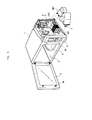
- Referring to Figure 5, the interior of an
oven body 1 is partitioned into a electrical component chamber 2 and a cooking chamber 4. A variety of electric devices, including a lamp 7, acooling fan 8, a magnetron MGT, a high-voltage transformer HVT, a high-voltage capacitor HVC, are positioned in the electrical component chamber 2. A rotary tray 5 is mounted on the bottom of the cooking chamber 4 to hold food, and adoor 3 is hingedly attached to one side of theoven body 1 for providing access to the cooking chamber 4. A control panel 6 is provided at the of theoven body 1 in front of the electrical component chamber 2. - A
hook 3a is received by arecess 3b when thedoor 3 is closed and withdrawn from therecess 3b when thedoor 3 is opened. A microswitch (not shown) is open or closed depending on the position of thehook 3a to provide a door open/closed signal to control means (not shown). Accordingly, the control means recognizes opening and closing of thedoor 3 and controls the operation of the magnetron to prevent the generation of microwaves when the door is open. - However, although a microwave oven is provided with a seal structure that is capable of preventing microwaves generated by a magnetron from leaking out of a cooking chamber, there are persons who have fears that the microwaves may escape from the cooking chamber. Some persons avoid using the microwave ovens for fear of microwaves.
- In conventional microwave ovens, a lamp 7 is automatically turned on to illuminate the cooking chamber 4 when the
door 3 is opened and turned off when thedoor 3 is closed. Accordingly, if the door is left open, the lamp 7 is unnecessarily kept on, thereby wasting electric power. - A microwave oven according to the present invention is characterised by proximity detection means for detecting the proximity of a person and the control means being responsive to the proximity detection means to modify the operation of the oven in dependence on the proximity of a person.
- Preferably, a microwave oven according to the present invention includes a cooking chamber, a cooking chamber door, a cooking chamber door state sensor and a light for illuminating the cooking chamber, and the control means is further responsive to the cooking chamber door state sensor to energise the light in the event that the door is open and a person is detected by the proximity detection means and de-energise the light in the event that the door is open and a person is not detected by the proximity detection means.
- Preferably, a microwave oven according to the present invention includes a microwave generator and the control means is configured to de-energise the microwave generator in the event that the proximity detection means detects the presence of a person.
- Preferably, the proximity detection means comprises an infrared transmitter and an infrared receiver.
- An embodiment of the present invention will now be described, by way of example, with reference to Figures 1 to 4 of the accompanying drawings, in which:
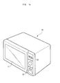
- Figure 1a is a perspective view showing a microwave oven in accordance with the present invention;
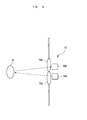
- Figure 1b is a horizontal sectional view showing the construction and operation of the body detecting sensor of the microwave oven of Figure 1a;
- Figure 2 is a view showing the sensing area of the body detecting sensor;
- Figure 3 is a block diagram of the microwave oven of Figure 1a;
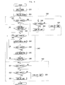
- Figure 4 is a flowchart showing a method for controlling the microwave oven of Figure 1a in accordance with the present invention; and
- Figure 5 is a perspective view of a conventional microwave oven.
-
- The microwave oven of the present invention comprises the same component elements as a conventional microwave oven illustrated in Figure 5 and, additionally, a
body detecting sensor 13. - As shown in Figure 1a, the
body detecting sensor 13 is formed in acontrol panel 12 at the front of a microwave oven according to the present invention. Thebody detecting sensor 13 detects the presence of a user when a user approaches the microwave oven to open or close thedoor 11 of the microwave oven or to input cooking information, such as a cooking type and a cooking time period. - The
body detecting sensor 13, as shown in Figure 1b, is comprised of alight emitting element 14a for emitting infrared rays in a forward direction from the oven'sbody 10, alight receiving element 14b for receiving infrared rays reflected from a human body "A", and alenses elements lenses angle lens 15a for widely diffusing infrared rays over a sensing area, and acondensing lens 15b for focusing infrared rays onto thelight receiving element 14b. - The
body detecting sensor 13 is mounted on theoven body 10 at a position such that it covers a desired sensing area, i.e. the region where is user will stand in order to operate the oven. Referring to Figure 2, thebody detecting sensor 13 is preferably located at a position where thebody detecting sensor 13 detects a user entering the desired sensing area extending over a certain area in front of theoven body 10. - Referring to Figure 3, the microwave oven includes the
body detecting sensor 13 which is connected to the input terminal of amicroprocessor 40, akey input unit 20, a door open/closedsensing unit 30, amagnetron operating unit 50 connected to an output terminal of themicroprocessor 40, and alamp operating unit 60 connected to an output terminal of themicroprocessor 40. - The
body detecting sensor 13 is comprised of thelight emitting element 14a for radiating high-frequency modulated infrared rays throughout the sensing area through the wide-angle lens 15a, thelight receiving element 14b for receiving infrared rays reflected by a human body "A" and focused by thecondensing lens 15b, and asignal processing unit 16 for high-pass filtering and amplifying infrared signals received through thelight receiving element 14b. In detail, thesignal processing unit 16 filters and amplifies the high frequency components of the output of thelight receiving element 14b and outputs them to themicroprocessor 40 so as to detect the high frequency components of the infrared rays deflected from the human body, since ambient rays having a constant luminous intensity correspond to low frequency components. - The
key input unit 20 is provided with a plurality of function keys for allowing a user to input cooking information such as a cooking type and a cooking time, and outputs a key signal corresponding to the key manipulated by the user to amicroprocessor 40. Themicroprocessor 40 receives cooking information corresponding to the key signals, and controls the cooking operation corresponding to the received cooking information. - The door open/closed
sensing unit 30 outputs a door open/closed signal generated by a microswitch (not shown) according to whether thedoor 3 is open or closed, and themicroprocessor 40 recognizes the opening and closing of thedoor 11 according to the door open/closed signals. - The
magnetron operating unit 50 generates microwaves and stops the generation of microwaves by disconnecting the magnetron from its power source according to a control signal from themicroprocessor 40. - The
lamp operating unit 60 turns the lamp on and off according to a control signal from themicroprocessor 40. - When a user approaches the
oven body 10 and opens thedoor 11 so as to put food into the microwave oven, themicroprocessor 40 recognizes the approach of the user by means of thebody detecting sensor 13 and the opening of thedoor 11 by means of the door open/closedsensing unit 30, and outputs a control signal to thelamp operating unit 60 to turn on the lamp. Meanwhile, when the user retreats from theoven body 10 or closes thedoor 11, themicroprocessor 40 recognizes the retreat of the user by means of thebody detecting sensor 13 or the closing ofdoor 11 by means of the door open/closedsensing unit 30, and outputs a control signal to thelamp operating unit 60 to turn off the lamp. Accordingly, the lamp is turned on when a user is present in the sensing area and turned off when the user retreats from the sensing area, so the cooking chamber is illuminated for the necessary time period only. - When a user approaches the
oven body 10 and opens thedoor 11 so as to take food out from the microwave oven, themicroprocessor 40 controls the lamp to be turned on only while the user is present in the sensing area. As in the case where food is put into the microwave oven, themicroprocessor 40 controls the lamp to be turned on when a user is present in the sensing area and to be turned off when the user retreats from the sensing area, so the cooking chamber is illuminated for the necessary time period only. - In the meantime, when a user inputs cooking information, such as a cooking type and a cooking time period, after putting food into the
oven body 10 and closing thedoor 11, a cooking start signal is inputted to themicroprocessor 40. In this case, if the user is not present in the sensing area, that is, the user having completed the input of the cooking information retreats from the sensing area, themicroprocessor 40 outputs a control signal to themagnetron operating unit 50 to cook food by generating microwaves. - When a user approaches the
oven body 10 while the magnetron is operated, themicroprocessor 40 recognizes the entrance of the user to the sensing area by means of thebody detecting sensor 13, and outputs a control signal to themagnetron operating unit 50 to stop the magnetron, thereby stopping the generation of microwaves. Thereafter, when the user retreats from the sensing area, themicroprocessor 40 outputs a control signal to themagnetron operating unit 50 to re-start magnetron, thereby resuming the generation of microwaves. As described above, the operation in which the generation of high frequency waves is selectively stopped and resumed according to the approach to the sensing area and retreat of the user from the sensing area can be performed until the cooking operation of food is completed, so a user's fear of the leakage of high frequency waves can be eliminated. - Hereinafter, a method of controlling the microwave oven is described with reference to Figure 4.
- First of all, when electric power is applied to the microwave oven through an electric plug (S10), the
body detecting sensor 13 is activated (S20), so infrared rays are emitted from thelight emitting element 14a to the sensing area situated in front of theoven body 10. - Subsequently, the
microprocessor 40 performs a first operating mode in which the lamp is turned on while thedoor 11 is opened and the user is present in the sensing area (S30). In more detail, themicroprocessor 40 determines whether thedoor 11 is opened according to a door opening/closing signal from the door opening/closing detecting sensor 30 (S31). If thedoor 11 is opened, it is determined whether the user is present in the sensing area (S32). If the user is present in the sensing area, themicroprocessor 40 outputs a control signal to thelamp operating unit 60 to turn on the lamp (S33). If the user is not present in the sensing area, themicroprocessor 40 regards the lamp as being abandoned and outputs a control signal to thelamp operating unit 60 to turn off the lamp (S34) and the procedure returns to step S32 to keep the lamp turned off until a user approaches the oven body 10 (S32). - When the cooking information has been input at step S30 and the cooking start signal is input, the
microprocessor 40 performs a second operation mode in which the magnetron is operated to generate microwaves and, thereby, cook food only when a user retreats from the sensing area (S40). - In more detail, when the lamp is turned on at step S33, it is determined whether the cooking start signal has been input from the key input unit 20 (S41). This is because the cooking start signal is input after a user closes the door, puts food into the
oven body 10, and inputs cooking information including a cooking type and a cooking time period. If the cooking start signal is not input, themicroprocessor 40 regards food as being not having put into theoven body 10 and, therefore, the procedure returns to thestep 31. - If the cooking start signal is input, that is, the input of cooking information is completed while the
door 11 is closed, themicroprocessor 40 determines whether a user is present in the sensing area using the body detecting sensor 13 (S42). If a user is present in the sensing area, themicroprocessor 13 remains on standby. If a user is not present in the sensing area, themicroprocessor 40 outputs a control signal to themagnetron operating unit 50. As a result, operating power is applied to the magnetron, the magnetron generates microwaves, and a cooking operation is performed (S43). - While the microwave oven performs the cooking operation, it is determined whether a user is present in the sensing area using the body detecting sensor 13 (S44). If a user is not present in the sensing area, that is, a user has not approached the
oven body 10, the procedure returns to step S43 to keep the magnetron operating. If a user is present in the sensing area, that is, a user has not approached theoven body 10, themicroprocessor 40 outputs a control signal to themagnetron operating unit 50 to stop the operation of the magnetron, thereby stopping the generation of microwaves (S45). - Subsequently, the
microprocessor 40 determines whether the cooking time period set at the cooking information inputting step has expired (S46). If the cooking time period is not expired, the procedure returns to step S42 so as to resume the cooking operation by re-starting the magnetron after the user retreats from themicrowave oven 10. - If the cooking time period has expired, there is performed a third operation mode S50 in which the lamp is turned on only when a user enters the sensing area to take cooked food out from the microwave oven. That is, like the first operation mode S30, the lamp is turned on only when the door is opened and a user is present in the sensing area (S51, S52 and S53).
- If the door is closed, the
microprocessor 40 is on standby. Even if the door is opened, the lamp is turned off if the user retreats from the sensing area (S51, S52 and S54). - As described above, the present invention provides a microwave oven and method for controlling the same, which is capable of performing its cooking operation while a user is not present in a sensing area, thereby eliminating a user's fear of the leakage of high frequency waves.
- Additionally, the present invention provides a microwave oven and method for controlling the same, which is capable of turning on its lamp while a user is present in a sensing area, thereby preventing electric power from being wasted by a user's carelessness.
Claims (14)
- A microwave oven including control means (40, 50, 60), characterised by proximity detection means (13) for detecting the proximity of a person (A) and the control means (40, 50, 60) being responsive to the proximity detection means (13) to modify the operation of the oven in dependence on the proximity of a person (A).
- A microwave oven according to claim 1, including a cooking chamber, a cooking chamber door (11), a cooking chamber door state sensor (30) and a light for illuminating the cooking chamber, wherein the control means (40, 50, 60) is further responsive to the cooking chamber door state sensor (30) to energise the light in the event that the door (11) is open and a person (A) is detected by the proximity detection means (13) and de-energise the light in the event that the door (11) is open and a person (A) is not detected by the proximity detection means (13).
- A microwave oven according to claim 1 or 2, including a microwave generator, wherein the control means (40, 50, 60) is configured to de-energise the microwave generator in the event that the proximity detection means (13) detects the presence of a person (A).
- A microwave oven according to claim 1, 2 or 3, wherein the proximity detection means (13) comprises an infrared transmitter (14a) and an infrared receiver (14b).
- A microwave oven, said microwave oven being used to heat and cook food using high frequency waves generated by high frequency generating means provided in an oven body, comprising:body sensing means for detecting the presence of a user in a sensing area extended over a certain area in front of the oven body;first operating means for operating the high frequency generating means; andcontrol means for controlling the first operating means to selectively start, stop and resume the operation of the high frequency wave generating means according to the presence of a user in the sensing area.
- The microwave oven according to claim 5, wherein said body sensing means is a non-contact optical sensor for detecting the presence of a user without contact with the user.
- The microwave oven according to claim 5, wherein said body sensing means is mounted on the oven body at a position such that it covers a desired sensing area.
- The microwave oven according to claim 6, wherein said body sensing means comprises an infrared sensor for detecting the presence of a user in the sensing area in such a way that infrared rays emitted from a light emitting element enter a light receiving element, and a signal processing unit for high-pass-filtering and amplifying infrared signals entering the light receiving element.
- The microwave oven according to claim 8, further comprising a light guide member for widely diffusing emitted infrared rays over a sensing area and condensing refracted infrared rays.
- The microwave oven according to claim 9, wherein said light guide member consists of a wide-angle lens positioned in front of the light emitting element and a condensing lens positioned in front of the light receiving element.
- The microwave oven according to claim 5, further comprising a lamp for illuminating the cooking chamber of the oven body, second operating means for operating the lamp, and door opening/closing means for detecting the opening and closing of the door,
wherein said control means controls the second operating means to turn on or off the lamp according to the presence of a user in the sensing area while the door is closed. - A method for controlling a microwave oven, said microwave oven being used to heat and cook food using high frequency waves generated by high frequency generating means provided in an oven body, comprising the steps of:a) controlling the operation of a lamp according to the presence of a user in a sensing area extended over a certain area in front of the oven body in a first operation mode of putting food into the oven body;b) controlling the operation of a magnetron according to the presence of a user in the sensing area in a second operation mode of performing a cooking operation for a predetermined cooking time period; andc) controlling the operation of the lamp according to the presence of a user in the sensing area in a third operation mode of taking out food from the oven body.
- The method according to claim 12, wherein said first and third operating modes each comprise the steps of:turning on the lamp if the user is present in the sensing area; andturning off the lamp if the user is not present in the sensing area.
- The method according to claim 12, wherein said second operation mode comprises the steps of:starting the magnetron if a user is not present in the sensing area;stopping the magnetron if a user is present in the sensing area; andresuming the operation of the magnetron if a user is not present in the sensing area before the cooking time period is terminated.
Applications Claiming Priority (2)
| Application Number | Priority Date | Filing Date | Title |
|---|---|---|---|
| KR1020010041457A KR100782982B1 (en) | 2001-07-11 | 2001-07-11 | Microwave oven and method thereof |
| KR2001041457 | 2001-07-11 |
Publications (3)
| Publication Number | Publication Date |
|---|---|
| EP1276351A2 true EP1276351A2 (en) | 2003-01-15 |
| EP1276351A3 EP1276351A3 (en) | 2004-01-02 |
| EP1276351B1 EP1276351B1 (en) | 2009-04-08 |
Family
ID=19712038
Family Applications (1)
| Application Number | Title | Priority Date | Filing Date |
|---|---|---|---|
| EP01309743A Expired - Lifetime EP1276351B1 (en) | 2001-07-11 | 2001-11-19 | Microwave oven with proximity detector |
Country Status (6)
| Country | Link |
|---|---|
| US (1) | US6825453B2 (en) |
| EP (1) | EP1276351B1 (en) |
| JP (1) | JP3644920B2 (en) |
| KR (1) | KR100782982B1 (en) |
| CN (1) | CN1198081C (en) |
| DE (1) | DE60138274D1 (en) |
Cited By (2)
| Publication number | Priority date | Publication date | Assignee | Title |
|---|---|---|---|---|
| CN104007690A (en) * | 2014-06-09 | 2014-08-27 | 佛山市顺德区美的电热电器制造有限公司 | Control method and device of cooking appliance and cooking appliance |
| EP3038431A1 (en) * | 2014-12-26 | 2016-06-29 | LG Electronics Inc. | Circuit for driving cooker, system for driving cooker, cooker, and method for driving cooker |
Families Citing this family (15)
| Publication number | Priority date | Publication date | Assignee | Title |
|---|---|---|---|---|
| KR100672484B1 (en) * | 2005-07-15 | 2007-01-24 | 엘지전자 주식회사 | Apparatus and Method for Notifying Call in Absence of Mobile Terminal |
| KR101592026B1 (en) * | 2009-01-23 | 2016-02-04 | 엘지전자 주식회사 | A cooker and a method of controlling the same |
| US8564158B2 (en) | 2010-04-21 | 2013-10-22 | Electrolux Home Products, Inc. | Appliance having user detection functionality for controlling operation thereof |
| CN102625297B (en) * | 2011-01-27 | 2016-01-13 | 腾讯科技(深圳)有限公司 | For identity management method and the device of mobile terminal |
| CN102429576A (en) * | 2011-10-29 | 2012-05-02 | 常熟市董浜镇华进电器厂 | Intelligent electric heating kettle |
| CN103512058A (en) * | 2012-06-29 | 2014-01-15 | 太仓南极风能源设备有限公司 | Microwave oven |
| JP6503161B2 (en) * | 2014-07-11 | 2019-04-17 | パナソニック インテレクチュアル プロパティ コーポレーション オブ アメリカPanasonic Intellectual Property Corporation of America | Thermal power control device, thermal power control method and computer program |
| CN105006143A (en) * | 2015-07-20 | 2015-10-28 | 广东格兰仕微波炉电器制造有限公司 | Light control panel for household appliances |
| CN106610603A (en) * | 2015-10-27 | 2017-05-03 | 小米科技有限责任公司 | Intelligent equipment control method and device, terminal and intelligent equipment |
| CN107305024B (en) * | 2016-04-19 | 2019-03-15 | 北京小米移动软件有限公司 | The control method and device of micro-wave oven |
| US10527290B2 (en) * | 2017-01-27 | 2020-01-07 | Haier Us Appliance Solutions, Inc. | Oven appliance and methods of operation |
| JP7122144B2 (en) * | 2018-04-06 | 2022-08-19 | シャープ株式会社 | heating cooking equipment |
| CN109521686A (en) * | 2019-01-14 | 2019-03-26 | 杭州老板电器股份有限公司 | The Embedded kitchen appliance control device of intelligence and control method |
| CN112137385B (en) * | 2019-06-26 | 2021-08-06 | 佛山市顺德区美的电热电器制造有限公司 | Method and device for sensing user using behavior of cooking appliance and cooking appliance |
| JP2021143784A (en) | 2020-03-11 | 2021-09-24 | シャープ株式会社 | Determination device, heating cooker |
Citations (3)
| Publication number | Priority date | Publication date | Assignee | Title |
|---|---|---|---|---|
| JPH06300280A (en) * | 1993-04-13 | 1994-10-28 | Toshiba Corp | Heating cooker |
| GB2313924A (en) * | 1996-06-03 | 1997-12-10 | Mark Daniel Sheldon | Control device for domestic appliances |
| US6087643A (en) * | 1997-06-19 | 2000-07-11 | Daewoo Electronics Co., Ltd. | Method for controlling cavity lamp of microwave oven |
Family Cites Families (9)
| Publication number | Priority date | Publication date | Assignee | Title |
|---|---|---|---|---|
| JPH0233530A (en) * | 1988-07-21 | 1990-02-02 | Toshiba Corp | Cooking device |
| JPH03251619A (en) * | 1990-03-01 | 1991-11-11 | Mitsubishi Electric Corp | Cooking heater |
| JPH0526449A (en) * | 1991-07-22 | 1993-02-02 | Toshiba Corp | Heating cooking apparatus |
| JP3151501B2 (en) * | 1992-11-05 | 2001-04-03 | 株式会社電気工事西川組 | Gas cooker safety management system |
| KR950025356A (en) * | 1994-02-28 | 1995-09-15 | 배순훈 | High Light Control Device of Microwave Oven |
| KR980003214A (en) * | 1996-06-12 | 1998-03-30 | 김광호 | microwave |
| JPH10300100A (en) * | 1997-04-24 | 1998-11-13 | Sanyo Electric Co Ltd | Heating cooker |
| JP2000100636A (en) * | 1998-09-18 | 2000-04-07 | Impulse Giken:Kk | Power supply and apparatus for processing food material using the same |
| KR20010010531A (en) * | 1999-07-21 | 2001-02-15 | 전주범 | an apparatus for alaming an outputting of a microwave for microwave oven and a method thereof |
-
2001
- 2001-07-11 KR KR1020010041457A patent/KR100782982B1/en not_active IP Right Cessation
- 2001-10-19 US US09/981,836 patent/US6825453B2/en not_active Expired - Fee Related
- 2001-10-25 CN CNB011366559A patent/CN1198081C/en not_active Expired - Fee Related
- 2001-11-07 JP JP2001342496A patent/JP3644920B2/en not_active Expired - Fee Related
- 2001-11-19 DE DE60138274T patent/DE60138274D1/en not_active Expired - Lifetime
- 2001-11-19 EP EP01309743A patent/EP1276351B1/en not_active Expired - Lifetime
Patent Citations (3)
| Publication number | Priority date | Publication date | Assignee | Title |
|---|---|---|---|---|
| JPH06300280A (en) * | 1993-04-13 | 1994-10-28 | Toshiba Corp | Heating cooker |
| GB2313924A (en) * | 1996-06-03 | 1997-12-10 | Mark Daniel Sheldon | Control device for domestic appliances |
| US6087643A (en) * | 1997-06-19 | 2000-07-11 | Daewoo Electronics Co., Ltd. | Method for controlling cavity lamp of microwave oven |
Cited By (4)
| Publication number | Priority date | Publication date | Assignee | Title |
|---|---|---|---|---|
| CN104007690A (en) * | 2014-06-09 | 2014-08-27 | 佛山市顺德区美的电热电器制造有限公司 | Control method and device of cooking appliance and cooking appliance |
| CN104007690B (en) * | 2014-06-09 | 2017-04-05 | 佛山市顺德区美的电热电器制造有限公司 | The control method of cooking apparatus, control device and cooking apparatus |
| EP3038431A1 (en) * | 2014-12-26 | 2016-06-29 | LG Electronics Inc. | Circuit for driving cooker, system for driving cooker, cooker, and method for driving cooker |
| US10925126B2 (en) | 2014-12-26 | 2021-02-16 | Lg Electronics Inc. | Cooker |
Also Published As
| Publication number | Publication date |
|---|---|
| JP3644920B2 (en) | 2005-05-11 |
| EP1276351A3 (en) | 2004-01-02 |
| DE60138274D1 (en) | 2009-05-20 |
| US6825453B2 (en) | 2004-11-30 |
| CN1395064A (en) | 2003-02-05 |
| JP2003042455A (en) | 2003-02-13 |
| KR20030005948A (en) | 2003-01-23 |
| EP1276351B1 (en) | 2009-04-08 |
| KR100782982B1 (en) | 2007-12-07 |
| CN1198081C (en) | 2005-04-20 |
| US20030010776A1 (en) | 2003-01-16 |
Similar Documents
| Publication | Publication Date | Title |
|---|---|---|
| EP1276351A2 (en) | Microwave oven with proximity detector | |
| RU2327217C2 (en) | Cooking equipment with bar code scanner and method of its control | |
| CA2225438C (en) | Cooking device with demonstration mode | |
| CN101398197A (en) | Micro-wave oven without microwave radiation | |
| KR101635048B1 (en) | Circuit for driving of cooker, system for driving of cooker, cooker and method for driving of cooker | |
| JP2003123997A (en) | Device and method for blocking leak of microwave in lighting system | |
| KR20170114840A (en) | Power management system using by human body detecting sensor and the control method thereof | |
| JP2771022B2 (en) | microwave | |
| JPS5944793A (en) | Cooling device | |
| KR920007543B1 (en) | Nonload detecting circuit for microwave oven | |
| JPH0233530A (en) | Cooking device | |
| KR0118054Y1 (en) | Safety device of microwave oven | |
| KR100210068B1 (en) | Control method for microwave oven | |
| JP3208267B2 (en) | Cooking device | |
| KR20010010531A (en) | an apparatus for alaming an outputting of a microwave for microwave oven and a method thereof | |
| JP4155294B2 (en) | Human body detection device | |
| KR19980057920A (en) | Food Cooling / Insulation Control Method | |
| KR20000020544U (en) | over-voltage alarm apparatus of microwave-oven | |
| JPH09152135A (en) | Cooking device | |
| KR950007095B1 (en) | Oven lamp auto control method of range | |
| KR19990042731A (en) | Power cooker control method | |
| JPH05340547A (en) | Thawing and heating device | |
| KR20020092658A (en) | Apparatus for sterilizing microwave oven and method therefor | |
| JPS5946425A (en) | Heat-cooking utensil | |
| JPH10284241A (en) | Heating device |
Legal Events
| Date | Code | Title | Description |
|---|---|---|---|
| PUAI | Public reference made under article 153(3) epc to a published international application that has entered the european phase |
Free format text: ORIGINAL CODE: 0009012 |
|
| AK | Designated contracting states |
Kind code of ref document: A2 Designated state(s): AT BE CH CY DE DK ES FI FR GB GR IE IT LI LU MC NL PT SE TR |
|
| AX | Request for extension of the european patent |
Free format text: AL;LT;LV;MK;RO;SI |
|
| PUAL | Search report despatched |
Free format text: ORIGINAL CODE: 0009013 |
|
| AK | Designated contracting states |
Kind code of ref document: A3 Designated state(s): AT BE CH CY DE DK ES FI FR GB GR IE IT LI LU MC NL PT SE TR |
|
| AX | Request for extension of the european patent |
Extension state: AL LT LV MK RO SI |
|
| 17P | Request for examination filed |
Effective date: 20040607 |
|
| AKX | Designation fees paid |
Designated state(s): DE FR GB |
|
| RAP1 | Party data changed (applicant data changed or rights of an application transferred) |
Owner name: SAMSUNG ELECTRONICS CO., LTD. |
|
| 17Q | First examination report despatched |
Effective date: 20040914 |
|
| GRAP | Despatch of communication of intention to grant a patent |
Free format text: ORIGINAL CODE: EPIDOSNIGR1 |
|
| GRAS | Grant fee paid |
Free format text: ORIGINAL CODE: EPIDOSNIGR3 |
|
| GRAA | (expected) grant |
Free format text: ORIGINAL CODE: 0009210 |
|
| AK | Designated contracting states |
Kind code of ref document: B1 Designated state(s): DE FR GB |
|
| REG | Reference to a national code |
Ref country code: GB Ref legal event code: FG4D |
|
| REF | Corresponds to: |
Ref document number: 60138274 Country of ref document: DE Date of ref document: 20090520 Kind code of ref document: P |
|
| PLBE | No opposition filed within time limit |
Free format text: ORIGINAL CODE: 0009261 |
|
| STAA | Information on the status of an ep patent application or granted ep patent |
Free format text: STATUS: NO OPPOSITION FILED WITHIN TIME LIMIT |
|
| 26N | No opposition filed |
Effective date: 20100111 |
|
| REG | Reference to a national code |
Ref country code: FR Ref legal event code: PLFP Year of fee payment: 15 |
|
| PGFP | Annual fee paid to national office [announced via postgrant information from national office to epo] |
Ref country code: FR Payment date: 20150625 Year of fee payment: 15 |
|
| PGFP | Annual fee paid to national office [announced via postgrant information from national office to epo] |
Ref country code: GB Payment date: 20151026 Year of fee payment: 15 Ref country code: DE Payment date: 20151028 Year of fee payment: 15 |
|
| REG | Reference to a national code |
Ref country code: DE Ref legal event code: R119 Ref document number: 60138274 Country of ref document: DE |
|
| GBPC | Gb: european patent ceased through non-payment of renewal fee |
Effective date: 20161119 |
|
| REG | Reference to a national code |
Ref country code: FR Ref legal event code: ST Effective date: 20170731 |
|
| PG25 | Lapsed in a contracting state [announced via postgrant information from national office to epo] |
Ref country code: FR Free format text: LAPSE BECAUSE OF NON-PAYMENT OF DUE FEES Effective date: 20161130 |
|
| PG25 | Lapsed in a contracting state [announced via postgrant information from national office to epo] |
Ref country code: GB Free format text: LAPSE BECAUSE OF NON-PAYMENT OF DUE FEES Effective date: 20161119 Ref country code: DE Free format text: LAPSE BECAUSE OF NON-PAYMENT OF DUE FEES Effective date: 20170601 |