EP1276210A1 - A method and device for manufacturing a stator core of a vehicle rotary electric machine - Google Patents
A method and device for manufacturing a stator core of a vehicle rotary electric machine Download PDFInfo
- Publication number
- EP1276210A1 EP1276210A1 EP02019090A EP02019090A EP1276210A1 EP 1276210 A1 EP1276210 A1 EP 1276210A1 EP 02019090 A EP02019090 A EP 02019090A EP 02019090 A EP02019090 A EP 02019090A EP 1276210 A1 EP1276210 A1 EP 1276210A1
- Authority
- EP
- European Patent Office
- Prior art keywords
- magnetic
- stator core
- manufacturing
- pair
- magnetic strip
- Prior art date
- Legal status (The legal status is an assumption and is not a legal conclusion. Google has not performed a legal analysis and makes no representation as to the accuracy of the status listed.)
- Granted
Links
- 238000004519 manufacturing process Methods 0.000 title claims abstract description 18
- 238000000034 method Methods 0.000 title claims abstract description 9
- 238000010586 diagram Methods 0.000 description 4
- 239000004020 conductor Substances 0.000 description 3
- 229910000831 Steel Inorganic materials 0.000 description 2
- 230000004907 flux Effects 0.000 description 2
- 239000010959 steel Substances 0.000 description 2
- 229910000576 Laminated steel Inorganic materials 0.000 description 1
- 230000007423 decrease Effects 0.000 description 1
- 239000000696 magnetic material Substances 0.000 description 1
- 238000012986 modification Methods 0.000 description 1
- 230000004048 modification Effects 0.000 description 1
- 238000004804 winding Methods 0.000 description 1
Images



Classifications
-
- H—ELECTRICITY
- H02—GENERATION; CONVERSION OR DISTRIBUTION OF ELECTRIC POWER
- H02K—DYNAMO-ELECTRIC MACHINES
- H02K15/00—Processes or apparatus specially adapted for manufacturing, assembling, maintaining or repairing of dynamo-electric machines
- H02K15/02—Processes or apparatus specially adapted for manufacturing, assembling, maintaining or repairing of dynamo-electric machines of stator or rotor bodies
- H02K15/021—Magnetic cores
-
- H—ELECTRICITY
- H02—GENERATION; CONVERSION OR DISTRIBUTION OF ELECTRIC POWER
- H02K—DYNAMO-ELECTRIC MACHINES
- H02K1/00—Details of the magnetic circuit
- H02K1/06—Details of the magnetic circuit characterised by the shape, form or construction
- H02K1/12—Stationary parts of the magnetic circuit
- H02K1/16—Stator cores with slots for windings
-
- H—ELECTRICITY
- H02—GENERATION; CONVERSION OR DISTRIBUTION OF ELECTRIC POWER
- H02K—DYNAMO-ELECTRIC MACHINES
- H02K15/00—Processes or apparatus specially adapted for manufacturing, assembling, maintaining or repairing of dynamo-electric machines
- H02K15/02—Processes or apparatus specially adapted for manufacturing, assembling, maintaining or repairing of dynamo-electric machines of stator or rotor bodies
- H02K15/021—Magnetic cores
- H02K15/026—Wound cores
-
- H—ELECTRICITY
- H02—GENERATION; CONVERSION OR DISTRIBUTION OF ELECTRIC POWER
- H02K—DYNAMO-ELECTRIC MACHINES
- H02K1/00—Details of the magnetic circuit
- H02K1/06—Details of the magnetic circuit characterised by the shape, form or construction
- H02K1/12—Stationary parts of the magnetic circuit
- H02K1/16—Stator cores with slots for windings
- H02K1/165—Shape, form or location of the slots
-
- Y—GENERAL TAGGING OF NEW TECHNOLOGICAL DEVELOPMENTS; GENERAL TAGGING OF CROSS-SECTIONAL TECHNOLOGIES SPANNING OVER SEVERAL SECTIONS OF THE IPC; TECHNICAL SUBJECTS COVERED BY FORMER USPC CROSS-REFERENCE ART COLLECTIONS [XRACs] AND DIGESTS
- Y10—TECHNICAL SUBJECTS COVERED BY FORMER USPC
- Y10T—TECHNICAL SUBJECTS COVERED BY FORMER US CLASSIFICATION
- Y10T29/00—Metal working
- Y10T29/49—Method of mechanical manufacture
- Y10T29/49002—Electrical device making
- Y10T29/49009—Dynamoelectric machine
-
- Y—GENERAL TAGGING OF NEW TECHNOLOGICAL DEVELOPMENTS; GENERAL TAGGING OF CROSS-SECTIONAL TECHNOLOGIES SPANNING OVER SEVERAL SECTIONS OF THE IPC; TECHNICAL SUBJECTS COVERED BY FORMER USPC CROSS-REFERENCE ART COLLECTIONS [XRACs] AND DIGESTS
- Y10—TECHNICAL SUBJECTS COVERED BY FORMER USPC
- Y10T—TECHNICAL SUBJECTS COVERED BY FORMER US CLASSIFICATION
- Y10T29/00—Metal working
- Y10T29/49—Method of mechanical manufacture
- Y10T29/49002—Electrical device making
- Y10T29/49009—Dynamoelectric machine
- Y10T29/49012—Rotor
-
- Y—GENERAL TAGGING OF NEW TECHNOLOGICAL DEVELOPMENTS; GENERAL TAGGING OF CROSS-SECTIONAL TECHNOLOGIES SPANNING OVER SEVERAL SECTIONS OF THE IPC; TECHNICAL SUBJECTS COVERED BY FORMER USPC CROSS-REFERENCE ART COLLECTIONS [XRACs] AND DIGESTS
- Y10—TECHNICAL SUBJECTS COVERED BY FORMER USPC
- Y10T—TECHNICAL SUBJECTS COVERED BY FORMER US CLASSIFICATION
- Y10T29/00—Metal working
- Y10T29/49—Method of mechanical manufacture
- Y10T29/49002—Electrical device making
- Y10T29/4902—Electromagnet, transformer or inductor
- Y10T29/49071—Electromagnet, transformer or inductor by winding or coiling
-
- Y—GENERAL TAGGING OF NEW TECHNOLOGICAL DEVELOPMENTS; GENERAL TAGGING OF CROSS-SECTIONAL TECHNOLOGIES SPANNING OVER SEVERAL SECTIONS OF THE IPC; TECHNICAL SUBJECTS COVERED BY FORMER USPC CROSS-REFERENCE ART COLLECTIONS [XRACs] AND DIGESTS
- Y10—TECHNICAL SUBJECTS COVERED BY FORMER USPC
- Y10T—TECHNICAL SUBJECTS COVERED BY FORMER US CLASSIFICATION
- Y10T29/00—Metal working
- Y10T29/49—Method of mechanical manufacture
- Y10T29/49002—Electrical device making
- Y10T29/4902—Electromagnet, transformer or inductor
- Y10T29/49073—Electromagnet, transformer or inductor by assembling coil and core
Definitions
- the present invention relates to a method for manufacturing a stator core of a vehicle rotary electric machine according to claim 1. Moreover, the present invention also relates to a device for manufacturing a stator core of a vehicle rotary electric machine according to claim 4.
- the vehicle rotary electric machine can be comprised, for example, of an AC generator to be mounted in a passenger car, a truck, etc.
- a magnetic stator core is usually comprised of a spirally wound magnetic strip.
- Such a stator core can provide a high yield percentage of magnetic material and can be manufactured at a high manufacturing speed.
- conductors are to be disposed in the slots of the stator core at as a high space factor as possible.
- a pair long and thin magnetic sheets is stamped out to form a pair of magnetic strips that has a plurality of teeth and a core back in order to increase the yield percentage of the magnetic strips, the teeth of one of the pair of magnetic strips are respectively formed from portions inside slots of the other magnetic strip.
- each the magnetic strip is spirally wound into a cylindrical stack with the slots of one layer being aligned with those of another layer until the cylindrical stack has a prescribed thickness. Then, the stack is welded or riveted. Because two or more magnetic strips are formed at one time, the manpower and cost for manufacturing the stator cores can be reduced.
- JP-A-48-24204 discloses teeth whose tooth width becomes narrower toward the core back. In other words, slot width is widened at the middle thereof. This reduces strain of the strip when it is spirally wound and makes the size and shape of a cylindrical stator core accurate.
- each tooth has a pair of circumferential projections to increase the width of the tooth.
- the slot area is narrowed to thereby widen the cross-section of the tooth if the teeth of one of the pair of magnetic strips are respectively formed from portions inside slots of the other magnetic strip as disclosed in JP-A-299136, it is not possible to provide such a circumferentially wide tooth.
- tooth width is narrowed at the middle thereof as shown in JP-A-48-24204, a widened tooth edge of one of a pair of magnetic strips can be formed from the portion inside a widened slot of the other magnetic strip.
- the tooth is narrowed at the middle, the magnetic reluctance of the teeth increases, and the magnetic flux flowing through the stator core decreases significantly. This lowers the output power.
- a stator core of a vehicle AC generator that has an outside diameter between 90 mm and 140 mm is usually comprised of a laminated steel strip of a thickness between 0.5 mm and 1.0 mm. It is necessary to have a margin (or clearance) if teeth and slots are formed from a steel strip of the above thickness.
- the edge of the sheet may be drawn because of the low rigidity thereof.
- the projections of the tooth edge cannot have proper length, and a sufficient cross-section of the magnetic flux from the rotor cannot be provided.
- the magnetic strip is thicker than 0,2 mm and thinner than 0,5 mm.
- the invention can be applied to a vehicle rotary electric machine such as a generator or a motor.
- a vehicle rotary electric machine such as a generator or a motor.
- it is mounted in an engine and driven by the engine as an AC generator. It is also mounted in an engine as a motor.
- a stator core of a vehicle AC generator is described with reference to Figs. 1 - 5 .
- a cylindrical stator core 1 is comprised of a spirally wound and laminated magnetic strip 10 that is as thick as 0.35 mm.
- the magnetic strip 10 has a plurality of teeth 2 and a core back 3 from which the plurality of teeth 2 extends. When wound and laminated, tooth edges 20 of teeth 2 are disposed radially inside.
- a pair of circumferential notches 21 is formed at opposite sides of a base portion of each tooth 2 adjacent to the core back 3.
- a width B of the base between the notches 21 is set larger than a minimum width A between a pair of circumferential projections 201 formed at the tooth edge 20.
- Each slot 6 has a pair of walls 23 and 24 facing each other in the circumferential direction. The pair of walls 23 and 24 becomes parallel after the magnetic strip 10 is wound up.
- the pair of projections 201 is almost the same in shape as a slot bottom 210 that includes the pair of notches 21 .
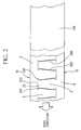
- a pair of magnetic strips 10 is formed from a long and thin magnetic sheet 100 such as a hoop of a steel sheet, the tooth edges 20 of one magnetic. strip 10 and the slot bottom 210 of the other magnetic strip 10 is sheared and separated without any clearance or margin except for clearances or marginal portions 200 at opposite sides of each tooth 2, as shown in Fig. 2. This increases the yield percentage of the magnetic strip. Because the thickness of the magnetic strip 10 is 0.35 mm, the projections 201 do not deform and keep the magnetic reluctance at a low level.
- the magnetic cross-section of the teeth 2 is thesmallest at the base of the projections 201, i.e. at the tooth edge 20 from which the projections 201 extend.
- the cross-section of middle portion of the teeth 2 between the base of the projections 201 and the core back 3 is not smaller than the magnetic cross-section at the base of the projections 201.
- the radial width of each notch 21 is narrowed when the magnetic strip 10 is spirally wound. Accordingly, the magnetic reluctance around the notches 21 is reduced when the stator core 1 is completed.
- a plurality of magnetic strips 10 can be formed from a single long and thin magnetic sheet 100, and the notches 21 make the winding step of the magnetic strip 10 easier.
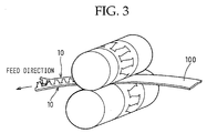
- a long magnetic sheet can be loaded between a pair of parallel rollers having a punch and a die to stamp out the magnetic strip 10 continuously, as shown in Fig. 3. Because the magnetic strip 10 can be formed continuously, the production time and cost can be reduced.
- the thickness of the magnetic sheets can be changed from 0.35 mm to a thickness between 0.2 mm and 0.5 mm.
- a stator core according to a second embodiment of the invention is described with reference to Fig. 4.
- a unit of the conductor coils 5 can be divided into two groups, and each output power is added to each other.
- the number of the slots per each unit length of the magnetic sheet becomes twice as many as the number of the slots of the magnetic sheet according to the first embodiment.
- the width of the slots becomes a half the width of the slot of the magnetic sheet according to the first embodiment.
- the clearance 200a for stamping out can be formed at a side of each tooth 2, as shown in Fig. 5. Because the width of the clearance can be increased, the magnetic strips can be stamped out more easily.
- the pair of magnetic strips can be formed by the pair of parallel rollers, as shown in Fig. 3.
- a clearance 200b can be increased until the notches at the base of the teeth 2 are removed. This makes the manufacturing steps easier and the manufacturing cost lower.
Landscapes
- Engineering & Computer Science (AREA)
- Power Engineering (AREA)
- Manufacturing & Machinery (AREA)
- Iron Core Of Rotating Electric Machines (AREA)
- Manufacture Of Motors, Generators (AREA)
- Windings For Motors And Generators (AREA)
- Insulation, Fastening Of Motor, Generator Windings (AREA)
Abstract
Description
- The present invention relates to a method for manufacturing a stator core of a vehicle rotary electric machine according to claim 1. Moreover, the present invention also relates to a device for manufacturing a stator core of a vehicle rotary electric machine according to
claim 4. The vehicle rotary electric machine can be comprised, for example, of an AC generator to be mounted in a passenger car, a truck, etc. - In order to supply an inexpensive vehicle rotary machine, a magnetic stator core is usually comprised of a spirally wound magnetic strip. Such a stator core can provide a high yield percentage of magnetic material and can be manufactured at a high manufacturing speed.
- In order to meet a recent demand for a high power generator, conductors are to be disposed in the slots of the stator core at as a high space factor as possible.
- As shown in JP-A11-299136, a pair long and thin magnetic sheets is stamped out to form a pair of magnetic strips that has a plurality of teeth and a core back in order to increase the yield percentage of the magnetic strips, the teeth of one of the pair of magnetic strips are respectively formed from portions inside slots of the other magnetic strip. Thereafter, each the magnetic strip is spirally wound into a cylindrical stack with the slots of one layer being aligned with those of another layer until the cylindrical stack has a prescribed thickness. Then, the stack is welded or riveted. Because two or more magnetic strips are formed at one time, the manpower and cost for manufacturing the stator cores can be reduced.
- In order to moderate stress of a magnetic strip when it is spirally wound, JP-A-48-24204 discloses teeth whose tooth width becomes narrower toward the core back. In other words, slot width is widened at the middle thereof. This reduces strain of the strip when it is spirally wound and makes the size and shape of a cylindrical stator core accurate.
- Because the magnetic reluctance of the air gap between the rotor and the stator is the largest in the magnetic circuit of a generator, the tooth edge formed at the inner periphery of the stator has a wider cross-section of a magnetic path than the rest of the tooth. In other words, each tooth has a pair of circumferential projections to increase the width of the tooth.
- As the space factor of the conductors increases, the slot area is narrowed to thereby widen the cross-section of the tooth if the teeth of one of the pair of magnetic strips are respectively formed from portions inside slots of the other magnetic strip as disclosed in JP-A-299136, it is not possible to provide such a circumferentially wide tooth.
- If the tooth width is narrowed at the middle thereof as shown in JP-A-48-24204, a widened tooth edge of one of a pair of magnetic strips can be formed from the portion inside a widened slot of the other magnetic strip. However, if the tooth is narrowed at the middle, the magnetic reluctance of the teeth increases, and the magnetic flux flowing through the stator core decreases significantly. This lowers the output power.
- A stator core of a vehicle AC generator that has an outside diameter between 90 mm and 140 mm is usually comprised of a laminated steel strip of a thickness between 0.5 mm and 1.0 mm. It is necessary to have a margin (or clearance) if teeth and slots are formed from a steel strip of the above thickness.
- However, if the thickness is reduced to a thickness less than 0.2 mm, the edge of the sheet may be drawn because of the low rigidity thereof. As a result, the projections of the tooth edge cannot have proper length, and a sufficient cross-section of the magnetic flux from the rotor cannot be provided.
- It is an object of the present invention, to provide a method and a device for manufacturing a stator core of a vehicle rotary electric machine with which the stator core can be manufactured at a high yield percentage and a high speed.
- According to the inventive method this object is solved by the features of claim 1.
- Improved embodiments of the inventive method result from
subclaims - The inventive device for solving the above object results from
claim 4. - According to a further embodiment of the invention, which results from
claim 5, the magnetic strip is thicker than 0,2 mm and thinner than 0,5 mm. - Other objects, features and characteristics of the present invention as well as the functions of related parts of the present invention will became clear from a study of the following detailed description, the appended claims and the drawings. In the drawings:
- Fig. 1
- is a fragmentary enlarged view of an axial end of a stator core of a vehicle AC generator;
- Fig. 2
- is an explanatory diagram showing a step of manufacturing a pair of magnetic strips from a long and thin magnetic sheet;
- Fig. 3
- is an explanatory diagram showing a step of manufacturing magnetic strips according to a first embodiment of the invention;
- Fig. 4
- is a fragmentary cross-sectional view of a stator core according to a second embodiment of the invention;
- Fig. 5
- is an explanatory diagram showing a step of manufacturing magnetic strips according to a third embodiment of the invention; and
- Fig. 6
- is an explanatory diagram showing a step of manufacturing magnetic strips according to a variation of the third embodiment of the invention.
- The invention can be applied to a vehicle rotary electric machine such as a generator or a motor. For example, it is mounted in an engine and driven by the engine as an AC generator. It is also mounted in an engine as a motor.
- A stator core of a vehicle AC generator is described with reference to Figs. 1 - 5 .
- A cylindrical stator core 1 is comprised of a spirally wound and laminated
magnetic strip 10 that is as thick as 0.35 mm. Themagnetic strip 10 has a plurality ofteeth 2 and acore back 3 from which the plurality ofteeth 2 extends. When wound and laminated,tooth edges 20 ofteeth 2 are disposed radially inside. - A pair of
circumferential notches 21 is formed at opposite sides of a base portion of eachtooth 2 adjacent to thecore back 3. A width B of the base between thenotches 21 is set larger than a minimum width A between a pair ofcircumferential projections 201 formed at thetooth edge 20. Eachslot 6 has a pair ofwalls walls magnetic strip 10 is wound up. - The pair of
projections 201 is almost the same in shape as aslot bottom 210 that includes the pair ofnotches 21 . When a pair ofmagnetic strips 10 is formed from a long and thinmagnetic sheet 100 such as a hoop of a steel sheet, thetooth edges 20 of one magnetic.strip 10 and theslot bottom 210 of the othermagnetic strip 10 is sheared and separated without any clearance or margin except for clearances ormarginal portions 200 at opposite sides of eachtooth 2, as shown in Fig. 2. This increases the yield percentage of the magnetic strip. Because the thickness of themagnetic strip 10 is 0.35 mm, theprojections 201 do not deform and keep the magnetic reluctance at a low level. - Thus, the magnetic cross-section of the
teeth 2 is thesmallest at the base of theprojections 201, i.e. at thetooth edge 20 from which theprojections 201 extend. In other words, the cross-section of middle portion of theteeth 2 between the base of theprojections 201 and thecore back 3 is not smaller than the magnetic cross-section at the base of theprojections 201. The radial width of eachnotch 21 is narrowed when themagnetic strip 10 is spirally wound. Accordingly, the magnetic reluctance around thenotches 21 is reduced when the stator core 1 is completed. - In addition, a plurality of
magnetic strips 10 can be formed from a single long and thinmagnetic sheet 100, and thenotches 21 make the winding step of themagnetic strip 10 easier. - As a method of manufacturing the stator core according to a first embodiment of the invention, a long magnetic sheet can be loaded between a pair of parallel rollers having a punch and a die to stamp out the
magnetic strip 10 continuously, as shown in Fig. 3. Because themagnetic strip 10 can be formed continuously, the production time and cost can be reduced. - The thickness of the magnetic sheets can be changed from 0.35 mm to a thickness between 0.2 mm and 0.5 mm.
- A stator core according to a second embodiment of the invention is described with reference to Fig. 4. A unit of the conductor coils 5 can be divided into two groups, and each output power is added to each other. The number of the slots per each unit length of the magnetic sheet becomes twice as many as the number of the slots of the magnetic sheet according to the first embodiment. On the other hand the width of the slots becomes a half the width of the slot of the magnetic sheet according to the first embodiment. Thus, the number of the notches increases so that the magnetic strip can be wound into a more accurate cylindrical shape at a low cost.
- As a method of manufacturing the stator core according to a third embodiment of the invention, the
clearance 200a for stamping out can be formed at a side of eachtooth 2, as shown in Fig. 5. Because the width of the clearance can be increased, the magnetic strips can be stamped out more easily. The pair of magnetic strips can be formed by the pair of parallel rollers, as shown in Fig. 3. - As a variation, a
clearance 200b can be increased until the notches at the base of theteeth 2 are removed. This makes the manufacturing steps easier and the manufacturing cost lower. - In the foregoing description of the present invention, the invention has been disclosed with reference to specific embodiments thereof. It will, however, be evident that various modifications and changes may be made to the specific embodiments of the present invention without departing from the scope of the invention as set forth in the appended claims. Accordingly, the description of the present invention is to be regarded in an illustrative, rather than a restrictive, sense.
Claims (5)
- A method of manufacturing a stator core (1) of a vehicle rotary electric machine characterized by comprising:a step of inserting a long thin magnetic sheet (100) between a pair of rollers; anda step of continuously stamping out a magnetic strip (10) having a plurality of teeth (2) and a core back portion (3) from said sheet (100) by said pair of rollers.
- A method according to claim 1, characterized in that the thickness of said magnetic sheet (100) is changed from 0,35 mm to a thickness between 0,2 mm and 0,5 mm.
- A method according to claim 1, characterized in that said magnetic strip (10) is wound into a cylindrical shape.
- A device for manufacturing a stator core (1) of a vehicle rotary electric machine, characterized by a pair of parallel rollers having a punch and a die to stamp out a magnetic strip (10) from a long and thin sheet (100), said magnetic strip (10) having a plurality of teeth (2) and a core back portion (3).
- A device according to claim 4, characterized in that the magnetic strip (10) is thicker than 0,2 mm and thinner than 0,5 mm.
Applications Claiming Priority (5)
| Application Number | Priority Date | Filing Date | Title |
|---|---|---|---|
| JP2000113966 | 2000-04-14 | ||
| JP2000113966 | 2000-04-14 | ||
| JP2000359639 | 2000-11-27 | ||
| JP2000359639A JP3656733B2 (en) | 2000-04-14 | 2000-11-27 | Stator for rotating electrical machine for vehicle and method for manufacturing the same |
| EP01108645A EP1146624B1 (en) | 2000-04-14 | 2001-04-05 | Stator core of vehicle rotary electric machine and method of manufacturing the same |
Related Parent Applications (1)
| Application Number | Title | Priority Date | Filing Date |
|---|---|---|---|
| EP01108645A Division EP1146624B1 (en) | 2000-04-14 | 2001-04-05 | Stator core of vehicle rotary electric machine and method of manufacturing the same |
Publications (2)
| Publication Number | Publication Date |
|---|---|
| EP1276210A1 true EP1276210A1 (en) | 2003-01-15 |
| EP1276210B1 EP1276210B1 (en) | 2006-06-21 |
Family
ID=26590162
Family Applications (2)
| Application Number | Title | Priority Date | Filing Date |
|---|---|---|---|
| EP01108645A Expired - Lifetime EP1146624B1 (en) | 2000-04-14 | 2001-04-05 | Stator core of vehicle rotary electric machine and method of manufacturing the same |
| EP02019090A Expired - Lifetime EP1276210B1 (en) | 2000-04-14 | 2001-04-05 | A method and device for manufacturing a stator core of a vehicle rotary electric machine |
Family Applications Before (1)
| Application Number | Title | Priority Date | Filing Date |
|---|---|---|---|
| EP01108645A Expired - Lifetime EP1146624B1 (en) | 2000-04-14 | 2001-04-05 | Stator core of vehicle rotary electric machine and method of manufacturing the same |
Country Status (4)
| Country | Link |
|---|---|
| US (2) | US6559572B2 (en) |
| EP (2) | EP1146624B1 (en) |
| JP (1) | JP3656733B2 (en) |
| DE (2) | DE60120953T2 (en) |
Families Citing this family (80)
| Publication number | Priority date | Publication date | Assignee | Title |
|---|---|---|---|---|
| JP4327960B2 (en) * | 1999-10-25 | 2009-09-09 | 富士通株式会社 | E-mail terminal device and computer-readable medium |
| SE516002C2 (en) * | 2000-03-01 | 2001-11-05 | Abb Ab | Rotary electric machine and method of making a stator winding |
| JP3960122B2 (en) * | 2002-05-01 | 2007-08-15 | 株式会社デンソー | Electric compressor |
| DE10245691A1 (en) * | 2002-09-30 | 2004-04-08 | Robert Bosch Gmbh | Stand for an electrical machine |
| JP4042612B2 (en) | 2003-04-11 | 2008-02-06 | 株式会社デンソー | Rotor for rotating electrical machine and method for manufacturing the same |
| US7271519B2 (en) * | 2003-10-02 | 2007-09-18 | Lg Electronics Inc. | Laminated body of motor and manufacturing method thereof |
| US7728481B2 (en) * | 2003-10-02 | 2010-06-01 | Lg Electronics Inc. | Laminated body of motor and manufacturing method thereof |
| KR100565652B1 (en) * | 2003-12-30 | 2006-03-30 | 엘지전자 주식회사 | driving unit in top loading drum type washing machine |
| KR101033579B1 (en) * | 2004-03-03 | 2011-05-11 | 엘지전자 주식회사 | Stator structure of outer rotor type motor for drum washing machine |
| KR101033573B1 (en) * | 2004-02-26 | 2011-05-11 | 엘지전자 주식회사 | Stator structure of outer rotor type motor for drum washing machine |
| US7362028B2 (en) * | 2004-02-26 | 2008-04-22 | Lg Electronics Inc. | Stator of outer rotor type motor for drum type washer |
| KR101033580B1 (en) * | 2004-03-03 | 2011-05-11 | 엘지전자 주식회사 | Structure of Spiral Core and Manufacturing Method Thereof |
| DE102004021740A1 (en) * | 2004-04-30 | 2005-11-24 | Thyssenkrupp Transrapid Gmbh | Stator packages for maglev trains |
| JP4798965B2 (en) * | 2004-05-31 | 2011-10-19 | 株式会社東芝 | Manufacturing method of rotating machine iron core |
| DE102004034526A1 (en) * | 2004-07-16 | 2006-02-16 | Elmotec Statomat Vertriebs Gmbh | Stator for electrical machines |
| US6989622B1 (en) | 2004-11-23 | 2006-01-24 | Visteon Global Technologies, Inc. | Alternator having claw-pole rotor |
| JP2006345671A (en) * | 2005-06-10 | 2006-12-21 | Denso Corp | Rotating electric machine for vehicles |
| US7536526B2 (en) * | 2005-07-11 | 2009-05-19 | General Electric Company | Hierarchical state based migration of structured data |
| DE102006016249A1 (en) * | 2006-03-31 | 2007-10-04 | Robert Bosch Gmbh | Stator for electrical machine, has grooves separated from each other by tooth, where ratio of mass of wires in groove to total mass of wire lies between specified values and groove slot width is equal to groove width |
| DE102006034109A1 (en) * | 2006-07-24 | 2008-01-31 | Robert Bosch Gmbh | Radial centering surface of a stand core |
| JP5061788B2 (en) * | 2007-08-10 | 2012-10-31 | トヨタ自動車株式会社 | Stator |
| US7939984B2 (en) * | 2007-10-30 | 2011-05-10 | Woodward Hrt, Inc. | Lamination having tapered tooth geometry which is suitable for use in electric motor |
| JPWO2010103634A1 (en) * | 2009-03-11 | 2012-09-10 | 株式会社日立製作所 | AC generator for vehicles |
| WO2011042036A1 (en) * | 2009-10-09 | 2011-04-14 | Thyssenkrupp Aufzugswerke Gmbh | Elevator drive |
| EP2309624A1 (en) | 2009-10-09 | 2011-04-13 | ThyssenKrupp Aufzugswerke GmbH | Elevator drive |
| EP2567450A4 (en) | 2010-05-04 | 2018-01-17 | Remy Technologies, LLC | Electric machine cooling system and method |
| US8659191B2 (en) | 2010-05-18 | 2014-02-25 | Remy Technologies, Llc | Sleeve member for an electric machine |
| DE112011101912T5 (en) | 2010-06-04 | 2013-03-28 | Remy Technologies Llc. | Cooling system and method for an electric machine |
| US8519581B2 (en) | 2010-06-08 | 2013-08-27 | Remy Technologies, Llc | Electric machine cooling system and method |
| JP2013528353A (en) | 2010-06-08 | 2013-07-08 | レミー テクノロジーズ リミテッド ライアビリティー カンパニー | Electromechanical cooling system and method |
| US8456046B2 (en) * | 2010-06-08 | 2013-06-04 | Remy Technologies, Llc | Gravity fed oil cooling for an electric machine |
| US8269383B2 (en) * | 2010-06-08 | 2012-09-18 | Remy Technologies, Llc | Electric machine cooling system and method |
| US8482169B2 (en) | 2010-06-14 | 2013-07-09 | Remy Technologies, Llc | Electric machine cooling system and method |
| US8552600B2 (en) | 2010-06-14 | 2013-10-08 | Remy Technologies, Llc | Potted end turns of an electric machine |
| US8614538B2 (en) | 2010-06-14 | 2013-12-24 | Remy Technologies, Llc | Electric machine cooling system and method |
| EP2587632B1 (en) * | 2010-06-25 | 2019-01-23 | Mitsubishi Electric Corporation | Laminated core for dynamo-electric machine |
| US8446056B2 (en) | 2010-09-29 | 2013-05-21 | Remy Technologies, Llc | Electric machine cooling system and method |
| US8508085B2 (en) | 2010-10-04 | 2013-08-13 | Remy Technologies, Llc | Internal cooling of stator assembly in an electric machine |
| US8492952B2 (en) | 2010-10-04 | 2013-07-23 | Remy Technologies, Llc | Coolant channels for electric machine stator |
| US8395287B2 (en) | 2010-10-04 | 2013-03-12 | Remy Technologies, Llc | Coolant channels for electric machine stator |
| US8593021B2 (en) | 2010-10-04 | 2013-11-26 | Remy Technologies, Llc | Coolant drainage system and method for electric machines |
| US8546983B2 (en) | 2010-10-14 | 2013-10-01 | Remy Technologies, Llc | Split drain system and method for an electric machine module |
| US8648506B2 (en) | 2010-11-09 | 2014-02-11 | Remy Technologies, Llc | Rotor lamination cooling system and method |
| US8497608B2 (en) | 2011-01-28 | 2013-07-30 | Remy Technologies, Llc | Electric machine cooling system and method |
| CN103415979B (en) * | 2011-03-08 | 2016-10-26 | 松下电器产业株式会社 | The stator of motor and motor |
| WO2012145302A2 (en) | 2011-04-18 | 2012-10-26 | Remy Technologies, Llc | Electric machine module cooling system and method |
| DE112011105199T5 (en) * | 2011-04-29 | 2014-01-30 | Mitsubishi Electric Corporation | Laminated iron core for a linear motor and related manufacturing process |
| US8692425B2 (en) | 2011-05-10 | 2014-04-08 | Remy Technologies, Llc | Cooling combinations for electric machines |
| US8803380B2 (en) | 2011-06-03 | 2014-08-12 | Remy Technologies, Llc | Electric machine module cooling system and method |
| JP5638475B2 (en) * | 2011-07-01 | 2014-12-10 | 三菱電機株式会社 | Laminated iron core of linear motor and method of manufacturing the same |
| US9041260B2 (en) | 2011-07-08 | 2015-05-26 | Remy Technologies, Llc | Cooling system and method for an electronic machine |
| US8803381B2 (en) | 2011-07-11 | 2014-08-12 | Remy Technologies, Llc | Electric machine with cooling pipe coiled around stator assembly |
| US8546982B2 (en) | 2011-07-12 | 2013-10-01 | Remy Technologies, Llc | Electric machine module cooling system and method |
| US9048710B2 (en) | 2011-08-29 | 2015-06-02 | Remy Technologies, Llc | Electric machine module cooling system and method |
| US8975792B2 (en) | 2011-09-13 | 2015-03-10 | Remy Technologies, Llc | Electric machine module cooling system and method |
| US8901789B2 (en) | 2011-10-07 | 2014-12-02 | Remy Technologies, Llc | Electric machine module |
| US9634529B2 (en) * | 2011-12-05 | 2017-04-25 | Fisher & Paykel Appliances Ltd. | Electrical machine |
| US9099900B2 (en) | 2011-12-06 | 2015-08-04 | Remy Technologies, Llc | Electric machine module cooling system and method |
| KR101306317B1 (en) * | 2012-01-11 | 2013-09-09 | 백서재 | The punch die and their product for preventing shot of the generator core in the process of punch and die |
| US8941274B2 (en) | 2012-03-23 | 2015-01-27 | Whirlpool Corporation | Stator for an electric motor of a washing machine and method of manufacturing the same |
| US9331543B2 (en) | 2012-04-05 | 2016-05-03 | Remy Technologies, Llc | Electric machine module cooling system and method |
| US10069375B2 (en) | 2012-05-02 | 2018-09-04 | Borgwarner Inc. | Electric machine module cooling system and method |
| WO2013188742A2 (en) * | 2012-06-15 | 2013-12-19 | Vasostar, Inc. | Magnet orientation and positioning sysetm, method and apparatus |
| TWI459688B (en) | 2012-10-19 | 2014-11-01 | Ind Tech Res Inst | Wound stator core |
| GB2502385B (en) * | 2012-11-15 | 2014-07-09 | Emiliane Trancerie Spa | Method and apparatus for producing cores for electrical machines |
| JP6079240B2 (en) * | 2013-01-08 | 2017-02-15 | トヨタ自動車株式会社 | Stator for rotating electric machine and rotating electric machine |
| CN104051387B (en) * | 2013-03-15 | 2017-01-18 | 台湾积体电路制造股份有限公司 | Metal Post Bonding Using Pre-Fabricated Metal Posts |
| US9263407B2 (en) | 2013-03-15 | 2016-02-16 | Taiwan Semiconductor Manufacturing Company, Ltd. | Method for manufacturing a plurality of metal posts |
| JP6214951B2 (en) | 2013-07-19 | 2017-10-18 | 株式会社三井ハイテック | Manufacturing method of strip-shaped stator core piece and mold apparatus used therefor |
| US9614406B2 (en) | 2013-09-16 | 2017-04-04 | Nidec Motor Corporation | Wedge for stator having overmolded insulation |
| US9479022B2 (en) | 2013-09-16 | 2016-10-25 | Nidec Motor Corporation | Stator tooth wire retention wings |
| JP6248566B2 (en) * | 2013-11-18 | 2017-12-20 | 株式会社デンソー | Stator core of rotating electrical machine and method for manufacturing the same |
| CN107925279B (en) * | 2015-09-18 | 2019-12-24 | 爱信艾达株式会社 | Rotating machines and stators |
| US10594175B2 (en) * | 2017-02-28 | 2020-03-17 | Hamilton Sundstrand Corporation | Electrical machine laminations |
| EP3879673A1 (en) * | 2020-03-11 | 2021-09-15 | Siemens Gamesa Renewable Energy A/S | Laminated core segment for stator or rotor of a generator for a wind turbine |
| KR102478369B1 (en) * | 2020-10-13 | 2022-12-16 | 엘지전자 주식회사 | Fan motor |
| CN112803630B (en) * | 2021-03-22 | 2021-12-31 | 湖南科技大学 | Noise reduction optimization design method for alternating-current traction motor |
| US11817741B2 (en) * | 2021-03-23 | 2023-11-14 | Ford Global Technologies, Llc | Electrified vehicle having electric machine stator with slot pocket |
| JPWO2024004437A1 (en) * | 2022-06-30 | 2024-01-04 | ||
| DE102024102667A1 (en) * | 2024-01-31 | 2025-07-31 | Schaeffler Technologies AG & Co. KG | Stator of an electric rotary machine and a method for producing a stator |
Citations (6)
| Publication number | Priority date | Publication date | Assignee | Title |
|---|---|---|---|---|
| US2845555A (en) * | 1955-09-12 | 1958-07-29 | Westinghouse Electric Corp | Motors |
| US3029403A (en) * | 1958-05-23 | 1962-04-10 | Honeywell Regulator Co | Magnetic core structures |
| US3283399A (en) * | 1964-03-11 | 1966-11-08 | Gen Electric | Method of forming electromagnetic cores |
| JPS5494603A (en) * | 1978-01-10 | 1979-07-26 | Mitsubishi Electric Corp | Rotor core of revolving armature and its manufacture |
| JPS5725139A (en) * | 1980-07-21 | 1982-02-09 | Mitsui Haitetsuku:Kk | Manufacture of laminated core |
| US4796451A (en) * | 1984-10-12 | 1989-01-10 | General Electric Company | Apparatus and method for continuously forming edgewise wound cores |
Family Cites Families (10)
| Publication number | Priority date | Publication date | Assignee | Title |
|---|---|---|---|---|
| JPS5341321B1 (en) * | 1971-07-30 | 1978-11-02 | ||
| US3886256A (en) * | 1971-07-30 | 1975-05-27 | Hitachi Ltd | Stator core for rotary electric machines and method of manufacturing the same |
| US4260925A (en) * | 1978-04-17 | 1981-04-07 | Barrett Edward L | Stator for an electromagnetic transducer |
| JPS5785552A (en) * | 1980-11-13 | 1982-05-28 | Nippon Denso Co Ltd | Manufacture of core material of core for rotary electric machine |
| DE3110339C2 (en) * | 1981-03-17 | 1984-09-27 | Thyssen Industrie Ag, 4300 Essen | Method for manufacturing a laminated core for a long-stator linear motor |
| US4914934A (en) * | 1984-10-12 | 1990-04-10 | General Electric Company | Method of forming an edgewise wound core |
| EP0823771B1 (en) * | 1996-02-23 | 2006-04-26 | Matsushita Electric Industrial Co., Ltd. | Motor |
| JP3359863B2 (en) * | 1998-04-08 | 2002-12-24 | 三菱電機株式会社 | Manufacturing method of stator iron core |
| EP0961384B1 (en) * | 1998-05-25 | 2005-02-09 | Denso Corporation | Stator of vehicle ac generator and method of manufacturing the same |
| JP3538039B2 (en) * | 1998-10-23 | 2004-06-14 | 三菱電機株式会社 | Alternator |
-
2000
- 2000-11-27 JP JP2000359639A patent/JP3656733B2/en not_active Expired - Lifetime
-
2001
- 2001-04-05 DE DE60120953T patent/DE60120953T2/en not_active Expired - Lifetime
- 2001-04-05 DE DE60101111T patent/DE60101111T2/en not_active Expired - Lifetime
- 2001-04-05 EP EP01108645A patent/EP1146624B1/en not_active Expired - Lifetime
- 2001-04-05 EP EP02019090A patent/EP1276210B1/en not_active Expired - Lifetime
- 2001-04-06 US US09/827,213 patent/US6559572B2/en not_active Expired - Fee Related
-
2003
- 2003-02-24 US US10/370,709 patent/US7010846B2/en not_active Expired - Fee Related
Patent Citations (6)
| Publication number | Priority date | Publication date | Assignee | Title |
|---|---|---|---|---|
| US2845555A (en) * | 1955-09-12 | 1958-07-29 | Westinghouse Electric Corp | Motors |
| US3029403A (en) * | 1958-05-23 | 1962-04-10 | Honeywell Regulator Co | Magnetic core structures |
| US3283399A (en) * | 1964-03-11 | 1966-11-08 | Gen Electric | Method of forming electromagnetic cores |
| JPS5494603A (en) * | 1978-01-10 | 1979-07-26 | Mitsubishi Electric Corp | Rotor core of revolving armature and its manufacture |
| JPS5725139A (en) * | 1980-07-21 | 1982-02-09 | Mitsui Haitetsuku:Kk | Manufacture of laminated core |
| US4796451A (en) * | 1984-10-12 | 1989-01-10 | General Electric Company | Apparatus and method for continuously forming edgewise wound cores |
Non-Patent Citations (2)
| Title |
|---|
| PATENT ABSTRACTS OF JAPAN vol. 003, no. 117 (E - 141) 29 September 1979 (1979-09-29) * |
| PATENT ABSTRACTS OF JAPAN vol. 006, no. 091 (E - 109) 28 May 1982 (1982-05-28) * |
Also Published As
| Publication number | Publication date |
|---|---|
| US7010846B2 (en) | 2006-03-14 |
| DE60120953D1 (en) | 2006-08-03 |
| JP2001359246A (en) | 2001-12-26 |
| DE60101111D1 (en) | 2003-12-11 |
| EP1146624A3 (en) | 2001-11-21 |
| EP1146624B1 (en) | 2003-11-05 |
| DE60101111T2 (en) | 2004-08-19 |
| JP3656733B2 (en) | 2005-06-08 |
| US6559572B2 (en) | 2003-05-06 |
| EP1146624A2 (en) | 2001-10-17 |
| US20030127942A1 (en) | 2003-07-10 |
| DE60120953T2 (en) | 2006-12-21 |
| US20010030484A1 (en) | 2001-10-18 |
| EP1276210B1 (en) | 2006-06-21 |
Similar Documents
| Publication | Publication Date | Title |
|---|---|---|
| EP1276210B1 (en) | A method and device for manufacturing a stator core of a vehicle rotary electric machine | |
| US6317962B1 (en) | Method for producing a stator of an alternating-current dynamo-electric machine | |
| US6919665B2 (en) | Stator core, an electric motor in which it is utilized, and method of manufacturing a stator core | |
| JP5537964B2 (en) | Rotating electric machine | |
| US20120126659A1 (en) | Full round stator assembly and electromagnetic machine having high slot fill | |
| US20160254718A1 (en) | Segment conductors, stator, rotating electrical machine, and vehicle and method of manufacturing the segment conductors | |
| CN103378701A (en) | Rotor for a motor and a motor | |
| JP2010141961A (en) | Stator and method for manufacturing the stator | |
| CN107251370A (en) | Electric rotating machine and its manufacture method | |
| JP5190318B2 (en) | Permanent magnet type laminated iron core and manufacturing method thereof | |
| EP2690752A1 (en) | Stator core manufacturing method | |
| US20050264123A1 (en) | Stator of rotating electric machine and manufacturing method of the stator | |
| JP3964306B2 (en) | Method for manufacturing stator laminated iron core of electric motor | |
| JP2017005980A (en) | Magnetic core for electric motor | |
| JPS5915459B2 (en) | electromechanical magnetic circuit | |
| JP2932883B2 (en) | Stator core for motor and method of manufacturing stator core for motor | |
| US7009322B2 (en) | Rotor of rotary electric machine and method of manufacturing the rotor | |
| JP2000245081A (en) | Stator for DC motor and method of manufacturing the same | |
| JPH06133501A (en) | Electric motor stator laminated core and manufacturing method thereof | |
| JP2006230081A (en) | Motor stator | |
| US3270231A (en) | Dynamoelectric machine means | |
| US20230283121A1 (en) | Laminated core segment and method for producing same | |
| JP2000295801A (en) | Split type stator core | |
| US20220140668A1 (en) | Electric Machine and Method for Manufacture | |
| JP2001190048A (en) | Iron core punching method |
Legal Events
| Date | Code | Title | Description |
|---|---|---|---|
| PUAI | Public reference made under article 153(3) epc to a published international application that has entered the european phase |
Free format text: ORIGINAL CODE: 0009012 |
|
| 17P | Request for examination filed |
Effective date: 20020828 |
|
| AC | Divisional application: reference to earlier application |
Ref document number: 1146624 Country of ref document: EP |
|
| AK | Designated contracting states |
Kind code of ref document: A1 Designated state(s): AT BE CH CY DE DK ES FI FR GB GR IE IT LI LU MC NL PT SE TR |
|
| AX | Request for extension of the european patent |
Free format text: AL;LT;LV;MK;RO;SI |
|
| 17Q | First examination report despatched |
Effective date: 20030718 |
|
| AKX | Designation fees paid |
Designated state(s): DE FR GB IT |
|
| GRAP | Despatch of communication of intention to grant a patent |
Free format text: ORIGINAL CODE: EPIDOSNIGR1 |
|
| GRAJ | Information related to disapproval of communication of intention to grant by the applicant or resumption of examination proceedings by the epo deleted |
Free format text: ORIGINAL CODE: EPIDOSDIGR1 |
|
| GRAP | Despatch of communication of intention to grant a patent |
Free format text: ORIGINAL CODE: EPIDOSNIGR1 |
|
| GRAS | Grant fee paid |
Free format text: ORIGINAL CODE: EPIDOSNIGR3 |
|
| GRAA | (expected) grant |
Free format text: ORIGINAL CODE: 0009210 |
|
| AC | Divisional application: reference to earlier application |
Ref document number: 1146624 Country of ref document: EP Kind code of ref document: P |
|
| AK | Designated contracting states |
Kind code of ref document: B1 Designated state(s): DE FR GB IT |
|
| PG25 | Lapsed in a contracting state [announced via postgrant information from national office to epo] |
Ref country code: IT Free format text: LAPSE BECAUSE OF FAILURE TO SUBMIT A TRANSLATION OF THE DESCRIPTION OR TO PAY THE FEE WITHIN THE PRESCRIBED TIME-LIMIT;WARNING: LAPSES OF ITALIAN PATENTS WITH EFFECTIVE DATE BEFORE 2007 MAY HAVE OCCURRED AT ANY TIME BEFORE 2007. THE CORRECT EFFECTIVE DATE MAY BE DIFFERENT FROM THE ONE RECORDED. Effective date: 20060621 |
|
| REG | Reference to a national code |
Ref country code: GB Ref legal event code: FG4D |
|
| REF | Corresponds to: |
Ref document number: 60120953 Country of ref document: DE Date of ref document: 20060803 Kind code of ref document: P |
|
| ET | Fr: translation filed | ||
| REG | Reference to a national code |
Ref country code: GB Ref legal event code: 746 Effective date: 20061221 |
|
| PLBE | No opposition filed within time limit |
Free format text: ORIGINAL CODE: 0009261 |
|
| STAA | Information on the status of an ep patent application or granted ep patent |
Free format text: STATUS: NO OPPOSITION FILED WITHIN TIME LIMIT |
|
| 26N | No opposition filed |
Effective date: 20070322 |
|
| PGFP | Annual fee paid to national office [announced via postgrant information from national office to epo] |
Ref country code: GB Payment date: 20140422 Year of fee payment: 14 |
|
| PGFP | Annual fee paid to national office [announced via postgrant information from national office to epo] |
Ref country code: DE Payment date: 20140418 Year of fee payment: 14 Ref country code: FR Payment date: 20140422 Year of fee payment: 14 Ref country code: IT Payment date: 20140423 Year of fee payment: 14 |
|
| REG | Reference to a national code |
Ref country code: DE Ref legal event code: R119 Ref document number: 60120953 Country of ref document: DE |
|
| GBPC | Gb: european patent ceased through non-payment of renewal fee |
Effective date: 20150405 |
|
| PG25 | Lapsed in a contracting state [announced via postgrant information from national office to epo] |
Ref country code: DE Free format text: LAPSE BECAUSE OF NON-PAYMENT OF DUE FEES Effective date: 20151103 Ref country code: GB Free format text: LAPSE BECAUSE OF NON-PAYMENT OF DUE FEES Effective date: 20150405 Ref country code: IT Free format text: LAPSE BECAUSE OF NON-PAYMENT OF DUE FEES Effective date: 20150405 |
|
| REG | Reference to a national code |
Ref country code: FR Ref legal event code: ST Effective date: 20151231 |
|
| PG25 | Lapsed in a contracting state [announced via postgrant information from national office to epo] |
Ref country code: FR Free format text: LAPSE BECAUSE OF NON-PAYMENT OF DUE FEES Effective date: 20150430 |