EP1276175A1 - Hybrid connector - Google Patents
Hybrid connector Download PDFInfo
- Publication number
- EP1276175A1 EP1276175A1 EP02015508A EP02015508A EP1276175A1 EP 1276175 A1 EP1276175 A1 EP 1276175A1 EP 02015508 A EP02015508 A EP 02015508A EP 02015508 A EP02015508 A EP 02015508A EP 1276175 A1 EP1276175 A1 EP 1276175A1
- Authority
- EP
- European Patent Office
- Prior art keywords
- module
- locking
- grid
- locking means
- gate
- Prior art date
- Legal status (The legal status is an assumption and is not a legal conclusion. Google has not performed a legal analysis and makes no representation as to the accuracy of the status listed.)
- Granted
Links
Images


Classifications
-
- H—ELECTRICITY
- H01—ELECTRIC ELEMENTS
- H01R—ELECTRICALLY-CONDUCTIVE CONNECTIONS; STRUCTURAL ASSOCIATIONS OF A PLURALITY OF MUTUALLY-INSULATED ELECTRICAL CONNECTING ELEMENTS; COUPLING DEVICES; CURRENT COLLECTORS
- H01R13/00—Details of coupling devices of the kinds covered by groups H01R12/70 or H01R24/00 - H01R33/00
- H01R13/40—Securing contact members in or to a base or case; Insulating of contact members
- H01R13/42—Securing in a demountable manner
- H01R13/436—Securing a plurality of contact members by one locking piece or operation
- H01R13/4361—Insertion of locking piece perpendicular to direction of contact insertion
- H01R13/4362—Insertion of locking piece perpendicular to direction of contact insertion comprising a temporary and a final locking position
-
- H—ELECTRICITY
- H01—ELECTRIC ELEMENTS
- H01R—ELECTRICALLY-CONDUCTIVE CONNECTIONS; STRUCTURAL ASSOCIATIONS OF A PLURALITY OF MUTUALLY-INSULATED ELECTRICAL CONNECTING ELEMENTS; COUPLING DEVICES; CURRENT COLLECTORS
- H01R13/00—Details of coupling devices of the kinds covered by groups H01R12/70 or H01R24/00 - H01R33/00
- H01R13/44—Means for preventing access to live contacts
- H01R13/447—Shutter or cover plate
- H01R13/453—Shutter or cover plate opened by engagement of counterpart
- H01R13/4538—Covers sliding or withdrawing in the direction of engagement
Definitions
- the present invention relates to a connector hybrid electrical system comprising a contact holder module having pin contacts.
- Pins contact pins are known, designed to be coupled to female contact holder modules.
- the pin contact carrier module comprises a series of contact pins of small diameter, for example less than 1 mm, in particular less than or equal to about 0.64 mm. Such pins are fragile and require protection prior to mating with female contacts of a female module.
- Connector modules are also known whose locking contacts uses a shutter device equipped with finger locking contacts, these fingers to be inserted into windows in the contacts are supported on a rear wall of contact.
- the object of the invention is in particular to remedy these problems.
- the means locking is a movable locking flap, advantageously pivotally mounted on the body or sliding relative to the body, or a comb of locking.
- the body has a front end, a rear end, and a room in which the grid moves, this room having an opening before facing towards the front end of the body and a back part adjacent pin contacts, this end being turned towards the back end of the body, the grid being movable in said chamber between a position adjacent front of the body opening and a position adjacent back of alveoli receiving the bodies of contacts and letting the pin contacts pass.
- the grid has one or more first fingers pointing to the rear end of the body.
- the grid also has one or several second fingers directed towards the front end of the body or the opening of the chamber, the one or more second fingers directed towards the front end being arranged to cooperate with a locking means of a complementary module, this locking means abutting against an element of the grid in case correct non-locking by means of locking said complementary module and prohibiting the coupling of the modules.
- a return element or spring acts on the grid to exert a force tending to push the grid towards the front opening of the module.
- the module comprises one or short-circuit means for short-circuiting one or more contacts, said short-circuit means being movable between a short-circuit position and a short-circuit position. non-short circuit, said short-circuit means being controlled by the grid of the module in question or by an element of a module partially inserted into the module in question.
- the contact short-circuit means (s) are controlled by the gate, the one or more short-circuit means being deactivated when one or more fingers of the gate are engaged in a receiving notch of the gate. locking means.
- the short-circuit means include contact blades, presenting advantageously a curved end portion or folded.
- the blades of contact acts as a means of recall or spring tending to push the gate towards the front opening of the module.
- Another subject of the invention is the use of one or modules according to the invention for producing coupling connectors between contact pins small diameter and female contacts.
- the body 1 has a front end 1A and a rear end 1B, the chamber 7 being open from side of the end 1A. This opening of the room being adapted to allow the engagement of a party a module door contact female in the room.
- Each flap 4, 5 comprises clipping means 9 cooperating with body 1 means to ensure the keeping the shutter in the locked position.
- Each flap 4, 5 consists of two lugs 10, 11 between which extends a plate 12 carrying the lugs 26.
- Each lug 10, 11 is profiled so as to form a channel 13 and a stop 14.
- the leg 10, 11 has a profile substantially in L.
- the gate 6 bears on its face turned towards the bottom of the chamber or towards the end 1B of the body four 15A, 15B (FIGS. 4 and 6), two being located on the along the left edge 16 of the grid, while the two others are located along the right edge 17 of the grid 6.
- the upper fingers 15A are intended for cooperate with the tabs 10, 11 of the upper flap 5, while the lower fingers 15B are intended for cooperate with the lugs 10, 11 of the lower flap 4.
- each finger 15A, 15B of the grid 6 is located respectively in front of a channel 13 of a leg 10, 11 of a component 4, 5.
- each finger 15A, 15B is adapted to be engaged in a channel 13 during a movement of the gate towards the end back of the body 1.
- the fingers 15A, 15B serve as means opposing the opening of shutters 4, 5.
- the fingers 15A, 15B prevent any voluntary opening or accidental flaps 4, 5.
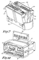
- a female module 21 able to cooperate with the module of FIG. 1 is schematically shown in FIG. FIG. 7.
- This female module comprises, for example also two contact locking flaps 22 females 23.
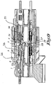
- the module of Figure 1 also includes blades short circuit 24 (FIGS. 8, 9 and 10) forming a short circuit of contacts as long as the module is not coupled to the female module.
- the elastic blades 24 act in the position of the figure 10 on the grid to push her towards the opening of room 7. Thus, during the uncoupling of the module of FIG. that of Figure 7, the elastic blades 24 push on the grid so as to ensure good protection pins from the beginning of the operation of separation of modules.
- the female module 21 (FIG. 7) has studs and pre-locking slots 30 and one or more pads and Final locking notches 31.
- the module presents also a polarization key 32 to be engaged in a throat 33 of room 7 of the body 1 (figure 1).
- the female module also has two 34 fooling fingers intended to be engaged in throats 35 of the chamber 7 when connecting the module of Figure 1 with the module of Figure 7.
- the polarization key 32 and the foolproof fingers 34 make it possible to avoid coupling the modules in in the opposite direction, but above all linear motion of the female module 21 with respect to the room 7.
- the flaps 22 may be of a similar type to that shown for the module of Figure 1, while the grid 6 has fingers (shown in broken lines in Figure 6 under the reference 15bis) turned towards the opening of Chamber 7. These 15bis fingers are meant to be engaged respectively in a channel of a paw of a shutter when the flaps 22 are in the locked position. These fingers 15a thus provide a function of because they prevent an opening accidental or not of a flap 22 during the coupling of the module 21 with the module of the figure 1.
- FIG 11 shows in perspective a similar module to that shown in Figure 1, except that this module has a locking comb 40 for inserted in a housing 41 of the module.
- This comb has notches 42 receiving rods 43 (shown in broken lines) in solidarity with the grid 6.
- the grid 6 also includes rods 44 turned forward and intended to work with a other module.
- each module may include pins and female parts.
- each module advantageously comprises a protection grid.
- the locking flap may be a non-pivoting flap, for example sliding.
- a separate locking system can be used to lock a shutter.
- this system of lock has a notch or window for receive a finger from the moving gate, when the locking system is in locked position.
Landscapes
- Details Of Connecting Devices For Male And Female Coupling (AREA)
- Coupling Device And Connection With Printed Circuit (AREA)
- Diaphragms For Electromechanical Transducers (AREA)
- Connector Housings Or Holding Contact Members (AREA)
Abstract
Description
La présente invention a pour objet un connecteur électrique hybride comprenant un module porte contacts comportant des contacts broches.The present invention relates to a connector hybrid electrical system comprising a contact holder module having pin contacts.
On connaít des modules porte contacts broches, destinés
à être accouplés à des modules porte contacts femelles.
Le module porte contacts broches comporte une série de
broches de contact de petit diamètre, par exemple
inférieur à 1 mm, en particulier inférieur ou égal à
environ 0,64 mm.
De telles broches sont fragiles et nécessitent une
protection avant leur accouplement avec des contacts
femelles d'un module femelle.Pins contact pins are known, designed to be coupled to female contact holder modules. The pin contact carrier module comprises a series of contact pins of small diameter, for example less than 1 mm, in particular less than or equal to about 0.64 mm.
Such pins are fragile and require protection prior to mating with female contacts of a female module.
On a déjà proposé de munir le module porte contact broche, dans sa partie avant d'accouplement avec le porte contact femelle, d'une grille avant mobile entre une position avancée de protection des broches et une position reculée permettant l'accouplement des deux modules. Un tel module comportant en outre un dispositif ressort agissant sur la grille est enseigné dans le document EP0948089.It has already been proposed to provide the contact holder module pin, in its front part of coupling with the female contact door, a movable front grille between an advanced position of pin protection and a retracted position allowing the coupling of the two modules. Such a module further comprising a spring device acting on the grid is taught in EP0948089.
On connaít également des modules connecteurs dont le verrouillage des contacts utilise un dispositif à volet muni de doigts de verrouillage des contacts, ces doigts venant soit s'insérer dans des fenêtres ménagées dans les contacts soit en appui sur une paroi arrière des contacts. Connector modules are also known whose locking contacts uses a shutter device equipped with finger locking contacts, these fingers to be inserted into windows in the contacts are supported on a rear wall of contact.
Le problème existant avec de tels modules est qu'il arrive que l'on tente d'accoupler un module porte contacts broches avec un module porte contacts femelles alors le verrouillage des contacts n'est pas correct. Un tel accouplement peut conduire à une mauvaise connexion. Par ailleurs, un désalignement lors de l'accouplement peut causer des problèmes divers, tels que pliage d'une ou de plusieurs broches, voire la destruction partielle ou totale d'une ou plusieurs broches.The problem with such modules is that it happens that we try to couple a door module pin contacts with a module contact female contacts then the locking of the contacts is not correct. Such mating can lead to bad connection. Moreover, a misalignment during Mating can cause various problems, such as that folding one or more pins or even the partial or total destruction of one or more pin.
L'invention a notamment pour but de remédier à ces problèmes.The object of the invention is in particular to remedy these problems.
Le module porte contacts selon l'invention comporte :
- un corps adapté pour recevoir au moins des contacts broches;
- au moins un moyen de verrouillage des contacts broches, ce moyen étant mobile par rapport au corps entre une position de non verrouillage et une position de verrouillage correct ;
- une grille avant montée mobile par rapport au corps entre une position avancée de protection des contacts broches et une position reculée permettant l'accouplement du module avec un module complémentaire,
- a body adapted to receive at least pin contacts;
- at least one means for locking the pin contacts, this means being movable relative to the body between a non-locking position and a correct locking position;
- a front grille mounted movable relative to the body between an advanced position of protection of the pin contacts and a retracted position for coupling the module with a complementary module,
De façon avantageuse, le moyen de blocage s'opposant à un mouvement de la grille avant en cas de non verrouillage correct par le moyen de verrouillage comporte:
- un doigt ou une tige solidaire du moyen de verrouillage ou de la grille mobile, et,
- une encoche formée dans la grille avant ou le moyen de verrouillage pour recevoir respectivement le doigt ou la tige solidaire du moyen de verrouillage ou le doigt ou la tige solidaire de la grille mobile, et
- une butée que présente la grille ou le moyen de verrouillage,
- a finger or a rod integral with the locking means or the movable grid, and
- a notch formed in the front gate or the locking means for respectively receiving the finger or the rod integral with the locking means or the finger or the rod integral with the movable gate, and
- a stop that presents the grid or the locking means,
Selon une forme de réalisation particulière, le moyen de verrouillage est un volet mobile de verrouillage, avantageusement monté à pivotement sur le corps ou à glissement par rapport au corps, ou un peigne de verrouillage.According to a particular embodiment, the means locking is a movable locking flap, advantageously pivotally mounted on the body or sliding relative to the body, or a comb of locking.
Selon une forme de réalisation avantageuse, le corps présente une extrémité avant, une extrémité arrière, et une chambre dans laquelle se déplace la grille, cette chambre présentant une ouverture avant tournée vers l'extrémité avant du corps et une partie arrière adjacente des contacts broches, cette extrémité étant tournée vers l'extrémité arrière du corps, la grille étant mobile dans ladite chambre entre une position avant adjacente de l'ouverture du corps et une position arrière adjacente des alvéoles recevant les corps de contacts et laissant passer les contacts broches. De préférence, la grille présente un ou plusieurs premiers doigts dirigés vers l'extrémité arrière du corps. Selon un détail d'une forme particulièrement avantageuse, la grille présente en outre un ou plusieurs seconds doigts dirigés vers l'extrémité avant du corps ou l'ouverture de la chambre, le ou lesdits seconds doigts dirigés vers l'extrémité avant étant agencés pour coopérer avec un moyen de verrouillage d'un module complémentaire, ce moyen de verrouillage venant en butée contre un élément de la grille en cas de non verrouillage correct par le moyen de verrouillage dudit module complémentaire et interdisant l'accouplement des modules.According to an advantageous embodiment, the body has a front end, a rear end, and a room in which the grid moves, this room having an opening before facing towards the front end of the body and a back part adjacent pin contacts, this end being turned towards the back end of the body, the grid being movable in said chamber between a position adjacent front of the body opening and a position adjacent back of alveoli receiving the bodies of contacts and letting the pin contacts pass. Of preferably, the grid has one or more first fingers pointing to the rear end of the body. According to a detail of a particularly advantageous, the grid also has one or several second fingers directed towards the front end of the body or the opening of the chamber, the one or more second fingers directed towards the front end being arranged to cooperate with a locking means of a complementary module, this locking means abutting against an element of the grid in case correct non-locking by means of locking said complementary module and prohibiting the coupling of the modules.
Avantageusement, un élément de rappel ou ressort agit sur la grille pour exercer une force tendant à pousser la grille vers l'ouverture avant du module.Advantageously, a return element or spring acts on the grid to exert a force tending to push the grid towards the front opening of the module.
Selon une caractéristique avantageuse d'une forme de
réalisation, le module comporte un ou des moyens de
court circuit pour court-circuiter un ou plusieurs
contacts, le ou lesdits moyens de court-circuit étant
mobile entre une position de court circuit et une
position de non court-circuit, le ou lesdits moyens de
court-circuit étant commandés par la grille du module
considéré ou par un élément d'un module inséré
partiellement dans le module considéré.
De préférence, le ou les moyens de court-circuit de
contact(s) sont commandés par la grille, le ou lesdits
moyens de court-circuit étant désactivés lorsqu'un un
ou des doigts de la grille sont engagés dans une
encoche de réception du moyen de verrouillage.According to an advantageous characteristic of an embodiment, the module comprises one or short-circuit means for short-circuiting one or more contacts, said short-circuit means being movable between a short-circuit position and a short-circuit position. non-short circuit, said short-circuit means being controlled by the grid of the module in question or by an element of a module partially inserted into the module in question.
Preferably, the contact short-circuit means (s) are controlled by the gate, the one or more short-circuit means being deactivated when one or more fingers of the gate are engaged in a receiving notch of the gate. locking means.
Par exemple, le ou les moyens de court-circuit comprennent des lames de contact, présentant avantageusement une partie terminale recourbée ou pliée. Dans ce cas, avantageusement, les lames de contact joue le rôle de moyen de rappel ou ressort tendant à pousser la grille vers l'ouverture avant du module.For example, the short-circuit means (s) include contact blades, presenting advantageously a curved end portion or folded. In this case, advantageously, the blades of contact acts as a means of recall or spring tending to push the gate towards the front opening of the module.
L'invention a encore pour objet l'utilisation d'un ou de modules suivant l'invention pour réaliser des connecteurs d'accouplement entre des broches de contact de petit diamètre et des contacts femelles.Another subject of the invention is the use of one or modules according to the invention for producing coupling connectors between contact pins small diameter and female contacts.
De tels connecteurs sont notamment utilisés dans les domaines de l'automobileSuch connectors are used in particular in areas of the automobile
Des particularités et détails de formes de réalisation de modules selon l'invention ressortiront de la description détaillée suivante dans laquelle il est fait référence aux dessins ci-annexés.Features and details of embodiments of modules according to the invention will emerge from the following detailed description in which he is refers to the attached drawings.
Dans ces dessins,
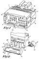
- La figure 1 est une vue d'ensemble d'un module comportant deux volets pivotants ;
- La figure 2 est une vue partielle en perspective du module de la figure 1, montrant les volets en position ouverte ;
- La figure 3 est une vue en perspective avec arrachement du module de la figure 1, avec les volets rabattus mais non en position verrouillée ;
- La figure 4 est une vue schématique montrant la position de la grille par rapport au volet supérieur du module dans la position de la figure 3 ;
- La figure 5 est une vue similaire à celle de la figure 3 si ce n'est que les volets sont en position verrouillée ;
- La figure 6 est une vue schématique montrant la position de la grille par rapport au volet supérieur du module de la figure 5 ;
- La figure 7 est une vue en perspective d'un module femelle coopérant avec le module de la figure 1 ;
- La figure 8 est une vue en coupe montrant l'introduction du module femelle dans le module mâle de la figure 1 ;
- La figure 9 est une vue en coupe montrant le module femelle partiellement accouplé au module mâle de la figure 1 ;
- La figure 10 est une vue en coupe montrant le module femelle accouplé au module mâle de la figure 1 ;
- La figure 11 est une vue schématique d'un module similaire à celui représenté à la figure 1, si ce n'est qu'il comporte un peigne de verrouillage.
- Figure 1 is an overview of a module with two pivoting flaps;
- Figure 2 is a partial perspective view of the module of Figure 1, showing the shutters in the open position;
- Figure 3 is a cutaway perspective view of the module of Figure 1, with the flaps folded but not in the locked position;
- Figure 4 is a schematic view showing the position of the gate relative to the upper flap of the module in the position of Figure 3;
- Figure 5 is a view similar to that of Figure 3 except that the shutters are in the locked position;
- Figure 6 is a schematic view showing the position of the gate relative to the upper flap of the module of Figure 5;
- Figure 7 is a perspective view of a female module cooperating with the module of Figure 1;
- Figure 8 is a sectional view showing the introduction of the female module into the male module of Figure 1;
- Figure 9 is a sectional view showing the female module partially coupled to the male module of Figure 1;
- Figure 10 is a sectional view showing the female module coupled to the male module of Figure 1;
- Figure 11 is a schematic view of a module similar to that shown in Figure 1, except that it comprises a locking comb.
Le module représenté aux figures 1, 2, 4 et 9 comporte :
- un corps 1 comportant une série de logements
ou alvéoles 2 recevant des contacts broches 3comportant un corps 3B reçu dansun alvéole 2 et une terminaison decontact 3A complémentaire d'uncontact femelle complémentaire 23, 51; - un volet inférieur 4 et
un volet supérieur 5 présentant une série d'ergots de verrouillage 26 pour assurer le maintien en place des contacts broches 3, les volets 4, 5 étant montés à pivotement par rapport au corps 1 ; - une grille de
protection 6 placée dans une chambre 7 du corps 1, cette grille étant mobile par rapport au corps 1 et présente une série de passages 8 pour les extrémités des broches 3A lors de l'accouplement du module avec un module porte contacts femelles complémentaire.
- a body 1 comprising a series of housings or
cells 2receiving pin contacts 3 comprising abody 3B received in acell 2 and acontact termination 3A complementary to a complementaryfemale contact 23, 51; - a lower flap 4 and an
upper flap 5 having a series of locking lugs 26 to ensure the holding in place of thepin contacts 3, theflaps 4, 5 being pivotally mounted relative to the body 1; - a
protective grid 6 placed in a chamber 7 of the body 1, this gate being movable relative to the body 1 and has a series of passages 8 for the ends of thepins 3A when coupling the module with a complementary female contact holder module .
Le corps 1 présente une extrémité avant 1A et une
extrémité arrière 1B, la chambre 7 étant ouverte du
côté de l'extrémité 1A. Cette ouverture de la chambre
étant adaptée pour permettre l'engagement d'une partie
d'un module porte contacts femelles dans la chambre.The body 1 has a
Chaque volet 4, 5 comporte des moyens de clipsage 9
coopérant avec des moyens du corps 1 pour assurer le
maintien en position verrouillée du volet. Chaque
volet 4, 5 est constitué de deux pattes 10, 11 entre
lesquelles s'étend un plat 12 portant les ergots 26.
Chaque patte 10, 11 est profilée de manière à former un
canal 13 et une butée 14. La patte 10, 11 a un profil
sensiblement en L. Each
La grille 6 porte sur sa face tournée vers le fond de
la chambre ou vers l'extrémité 1B du corps quatre
doigts 15A, 15B (figures 4 et 6), deux étant situés le
long du bord gauche 16 de la grille, tandis que les
deux autres sont situés le long du bord droit 17 de la
grille 6. Les doigts supérieurs 15A sont destinés à
coopérer avec les pattes 10, 11 du volet supérieur 5,
tandis que les doigts inférieurs 15B sont destinés à
coopérer avec les pattes 10, 11 du volet inférieur 4.The
En cas de non verrouillage correct d'un volet ou des
deux volets 4, 5, (position montrée aux figures 3 et
4), les doigts 15A de la grille 6 prennent appui sur la
butée 14 des pattes 10, 11 du ou des volets non
verrouillés correctement. De ce fait tout mouvement de
la grille vers l'extrémité 1B du corps est impossible,
de sorte qu'il n'est pas possible d'accoupler le module
avec un module porte contacts femelles et de sorte que
les broches du module sont protégées.
A la figure 4, on a représenté le volet supérieur 5 et
la grille 6 distants l'un de l'autre. La ligne
interrompue 18 montre la position du doigt 15A par
rapport à la patte 11. En réalité le doigt 15A est
adjacent de la patte 11.In the event of the non-locking of one or both
In Figure 4, there is shown the
En cas de verrouillage correct des volets 4, 5 par
rapport au corps 1 (position montrée aux figures 5 et
6), les quatre doigts 15A, 15B de la grille 6 sont
situés respectivement en face d'un canal 13 d'une patte
10, 11 d'un volet 4, 5. Dans cette position, chaque
doigt 15A, 15B est apte à être engagé dans un canal 13
lors d'un mouvement de la grille vers l'extrémité
arrière du corps 1. Lorsque les doigts de la grille 6
sont engagés dans les canaux 13 des pattes 10, 11 des
volets, les doigts 15A, 15B servent de moyens
s'opposant à l'ouverture des volets 4, 5. En d'autres
termes, lors de l'accouplement du module, les doigts
15A, 15B empêchent toute ouverture volontaire ou
accidentelle des volets 4, 5.In case of correct locking of the
Un module femelle 21 apte à coopérer avec le module de
la figure 1 est montré de manière schématique à la
figure 7. Ce module femelle comporte par exemple
également deux volets de verrouillage 22 de contacts
femelles 23.A
Le module de la figure 1 comporte également des lames de court-circuit 24 (figures 8, 9 et 10) formant un court-circuit de contacts tant que le module n'est pas accouplé au module femelle.The module of Figure 1 also includes blades short circuit 24 (FIGS. 8, 9 and 10) forming a short circuit of contacts as long as the module is not coupled to the female module.
Le mouvement des lames 24 d'une position de court-circuit
(voir figure 8) à une position de non court-circuit
(figure 10) est opéré grâce à des doigts 27
portés par la grille 6. La figure 9 montre un état
intermédiaire des modules entre eux. Ces doigts 27
agissent sur une partie courbée 28 de la lame élastique
24 lorsque l'accouplement des modules est presque
réalisé.The movement of the
Les lames élastiques 24 agissent dans la position de la
figure 10 sur la grille pour la pousser vers
l'ouverture de la chambre 7. Ainsi, lors du
désaccouplement du module de la figure 1 par rapport à
celui de la figure 7, les lames élastiques 24 poussent
sur la grille de manière à assurer une bonne protection
des broches depuis le début de l'opération de
séparation des modules.The
Le mouvement de la grille 6 vers le fond de la chambre
(vers l'extrémité 1B du module) est avantageusement
effectué à l'encontre de l'action d'un ou de plusieurs
ressorts 29. De tels ressorts assurent le retour de la
grille 6 dans une position permettant une protection
des broches avant l'accouplement du module de la figure
1.The movement of the
Le module femelle 21 (figure 7) présente des plots et
encoches de pré-verrouillage 30 et un ou des plots et
encoches de verrouillage final 31. Le module présente
également une clé de polarisation 32 destinée à être
engagée dans une gorge 33 de la chambre 7 du corps 1
(figure 1). Le module femelle présente en outre deux
doigts 34 de détrompage destinés à être engagés dans
des gorges 35 de la chambre 7 lors de la connexion du
module de la figure 1 avec le module de la figure 7.
La clé de polarisation 32 et les doigts de détrompage
34 permettent d'éviter un accouplement des modules en
sens inverse, mais permettent surtout d'assurer un
mouvement linéaire du module femelle 21 par rapport à
la chambre 7.The female module 21 (FIG. 7) has studs and
Pour éviter de pouvoir ouvrir les volets 22 du module
femelle, les volets 22 peuvent être d'un type similaire
à celui représenté pour le module de la figure 1,
tandis que la grille 6 présente des doigts (représentés
en trait interrompus à la figure 6 sous la référence
15bis) tournés vers l'ouverture de la chambre 7. Ces
doigts 15bis sont destinés à être engagés
respectivement dans un canal d'une patte d'un volet
lorsque les volets 22 sont en position verrouillée.
Ces doigts 15bis assurent ainsi une fonction de
sécurité puisqu'ils empêchent une ouverture
accidentelle ou non d'un volet 22 lors de
l'accouplement du module 21 avec le module de la figure
1.To avoid being able to open the
La figure 11 montre en perspective un module similaire
à celui représenté à la figure 1, si ce n'est que ce
module comporte un peigne de verrouillage 40 destinée à
être insérée dans un logement 41 du module. Ce peigne
présente des encoches 42 de réception de tiges 43
(montrées en traits interrompus) solidaires de la
grille 6. La grille 6 comporte également des tiges 44
tournées vers l'avant et destinées à travailler avec un
autre module.Figure 11 shows in perspective a similar module
to that shown in Figure 1, except that this
module has a locking
Les formes de réalisation des figures ci-annexées sont données à titre d'exemple uniquement. Il est clair que de nombreuses modifications sont possibles.The embodiments of the figures appended hereto are data as an example only. It's clear that many modifications are possible.
Ainsi, par exemple chaque module peut comprendre des
broches et des pièces femelles. Dans ce cas, chaque
module comporte avantageusement une grille de
protection.
Le volet de verrouillage peut être un volet non
pivotant, par exemple coulissant. Thus, for example each module may include pins and female parts. In this case, each module advantageously comprises a protection grid.
The locking flap may be a non-pivoting flap, for example sliding.
Eventuellement, un système de verrouillage distinct peut être utilisé pour le verrouillage d'un volet. Dans ce cas, de manière avantageuse, ce système de verrouillage présente une encoche ou fenêtre pour recevoir un doigt de la grille mobile, lorsque le système de verrouillage est en position verrouillée.Optionally, a separate locking system can be used to lock a shutter. In this case, advantageously, this system of lock has a notch or window for receive a finger from the moving gate, when the locking system is in locked position.
Claims (11)
Applications Claiming Priority (2)
| Application Number | Priority Date | Filing Date | Title |
|---|---|---|---|
| FR0109432A FR2827431A1 (en) | 2001-07-10 | 2001-07-10 | HYBRID CONNECTOR |
| FR0109432 | 2001-07-10 |
Publications (2)
| Publication Number | Publication Date |
|---|---|
| EP1276175A1 true EP1276175A1 (en) | 2003-01-15 |
| EP1276175B1 EP1276175B1 (en) | 2008-05-28 |
Family
ID=8865529
Family Applications (1)
| Application Number | Title | Priority Date | Filing Date |
|---|---|---|---|
| EP02015508A Expired - Lifetime EP1276175B1 (en) | 2001-07-10 | 2002-07-10 | Hybrid connector |
Country Status (5)
| Country | Link |
|---|---|
| EP (1) | EP1276175B1 (en) |
| AT (1) | ATE397308T1 (en) |
| DE (1) | DE60226812D1 (en) |
| ES (1) | ES2304410T3 (en) |
| FR (1) | FR2827431A1 (en) |
Cited By (3)
| Publication number | Priority date | Publication date | Assignee | Title |
|---|---|---|---|---|
| FR2864357A1 (en) * | 2003-12-19 | 2005-06-24 | Framatome Connectors Int | Electrical connector device, has stop unit opposing manipulation of locking device from releasing position to locking position, and rod supporting against corresponding breaker arm if contacts are partly inserted in socket |
| US8469752B2 (en) | 2009-07-20 | 2013-06-25 | Delphi International Operations Luxembourg, S.Ar.L | Electrical connector having shorting bar operation device |
| FR3013519A1 (en) * | 2013-11-19 | 2015-05-22 | Filec | ELECTRICAL CONNECTOR FOR USE IN A STEERING WHEEL OF A MOTOR VEHICLE |
Citations (4)
| Publication number | Priority date | Publication date | Assignee | Title |
|---|---|---|---|---|
| DE19704356A1 (en) * | 1996-02-05 | 1997-08-07 | Yazaki Corp | Multi-contact plug-connector |
| US5913697A (en) * | 1996-12-10 | 1999-06-22 | The Whitaker Corporation | Electrical connector having a secondary lock |
| US5964621A (en) * | 1998-06-25 | 1999-10-12 | The Whitaker Corporation | Connector assembly for multi-pocket header |
| US5997365A (en) * | 1997-03-10 | 1999-12-07 | Yazaki Corporation | Connector |
-
2001
- 2001-07-10 FR FR0109432A patent/FR2827431A1/en active Pending
-
2002
- 2002-07-10 DE DE60226812T patent/DE60226812D1/en not_active Expired - Lifetime
- 2002-07-10 AT AT02015508T patent/ATE397308T1/en not_active IP Right Cessation
- 2002-07-10 ES ES02015508T patent/ES2304410T3/en not_active Expired - Lifetime
- 2002-07-10 EP EP02015508A patent/EP1276175B1/en not_active Expired - Lifetime
Patent Citations (4)
| Publication number | Priority date | Publication date | Assignee | Title |
|---|---|---|---|---|
| DE19704356A1 (en) * | 1996-02-05 | 1997-08-07 | Yazaki Corp | Multi-contact plug-connector |
| US5913697A (en) * | 1996-12-10 | 1999-06-22 | The Whitaker Corporation | Electrical connector having a secondary lock |
| US5997365A (en) * | 1997-03-10 | 1999-12-07 | Yazaki Corporation | Connector |
| US5964621A (en) * | 1998-06-25 | 1999-10-12 | The Whitaker Corporation | Connector assembly for multi-pocket header |
Cited By (7)
| Publication number | Priority date | Publication date | Assignee | Title |
|---|---|---|---|---|
| FR2864357A1 (en) * | 2003-12-19 | 2005-06-24 | Framatome Connectors Int | Electrical connector device, has stop unit opposing manipulation of locking device from releasing position to locking position, and rod supporting against corresponding breaker arm if contacts are partly inserted in socket |
| WO2005069686A1 (en) * | 2003-12-19 | 2005-07-28 | Fci | Contact locking device for an electric connector and electric container containing said device |
| JP2007517362A (en) * | 2003-12-19 | 2007-06-28 | エフシーアイ | Contact locking device for electrical connector and electrical container containing said device |
| US7578709B2 (en) | 2003-12-19 | 2009-08-25 | Fci | Contact locking device for an electric connector and electric connector containing said device |
| JP4647620B2 (en) * | 2003-12-19 | 2011-03-09 | エフシーアイ | Contact locking device for electrical connector and electrical container containing said device |
| US8469752B2 (en) | 2009-07-20 | 2013-06-25 | Delphi International Operations Luxembourg, S.Ar.L | Electrical connector having shorting bar operation device |
| FR3013519A1 (en) * | 2013-11-19 | 2015-05-22 | Filec | ELECTRICAL CONNECTOR FOR USE IN A STEERING WHEEL OF A MOTOR VEHICLE |
Also Published As
| Publication number | Publication date |
|---|---|
| DE60226812D1 (en) | 2008-07-10 |
| ES2304410T3 (en) | 2008-10-16 |
| EP1276175B1 (en) | 2008-05-28 |
| FR2827431A1 (en) | 2003-01-17 |
| ATE397308T1 (en) | 2008-06-15 |
Similar Documents
| Publication | Publication Date | Title |
|---|---|---|
| EP2109189A1 (en) | Locking device for connector elements and connector comprising said device | |
| FR2889365A1 (en) | PIVOT LEVER TYPE CONNECTOR | |
| EP0643446A1 (en) | Improvements to electrical connector housings | |
| FR3049778A1 (en) | ELECTRICAL CONNECTOR WITH ROTATING CONNECTOR POSITION ASSURANCE DEVICE | |
| WO2011092431A1 (en) | Electric base and plug for the mains recharging of the batteries of an electric motor vehicle | |
| FR2805403A1 (en) | LEVER CONNECTOR | |
| EP2456021B1 (en) | Electric socket comprising translatably mobile side posts | |
| EP0673084B1 (en) | Housing element of an electrical connector | |
| EP1276175B1 (en) | Hybrid connector | |
| FR2706687A1 (en) | Electrical connector housing element. | |
| EP0207841A1 (en) | Mounting of electrical connecting elements | |
| EP0723314A1 (en) | Electrical connector | |
| EP0519815A1 (en) | Electrical connector | |
| EP0593343B1 (en) | Electrical connector with hermaphroditic contact elements | |
| FR2467490A1 (en) | ELECTRICAL CONNECTING DEVICE AND CASE FOR CONTAINING SUCH AN ORGAN | |
| FR2777392A1 (en) | Lockable electrical connector | |
| FR3010578A1 (en) | CONNECTOR WITH ELECTRICAL POSITION ASSURANCE DEVICE | |
| FR2828339A1 (en) | CONNECTION SYSTEM FOR A SPECIFIC CURRENT DISTRIBUTION NETWORK AND CORRESPONDING ADAPTER FOR CORRESPONDING PLUG EARTH AND SOCKET | |
| EP0949718B1 (en) | Connecting/disconnecting module for insulated electrical conductor pairs | |
| FR2785728A1 (en) | Electrical connector for inflatable air bags used for safety purposes in vehicles | |
| FR2655207A1 (en) | Electrical connector which includes improved terminal retention means | |
| FR2820245A1 (en) | Double locking connector having male element female unit with skirt connecting having passages with shutters above with finger section engaging passage sections | |
| EP1286427A1 (en) | Terminal-block with lock-arm for plug connector | |
| WO2024013256A1 (en) | Lug-cover assembly and associated drive system | |
| FR2813997A1 (en) | Connector for conductor wire to printed circuit has blade with flanges to retain wire and spaced contacts to fit into hole in circuit board |
Legal Events
| Date | Code | Title | Description |
|---|---|---|---|
| PUAI | Public reference made under article 153(3) epc to a published international application that has entered the european phase |
Free format text: ORIGINAL CODE: 0009012 |
|
| AK | Designated contracting states |
Kind code of ref document: A1 Designated state(s): AT BE BG CH CY CZ DE DK EE ES FI FR GB GR IE IT LI LU MC NL PT SE SK TR |
|
| AX | Request for extension of the european patent |
Free format text: AL;LT;LV;MK;RO;SI |
|
| 17P | Request for examination filed |
Effective date: 20030702 |
|
| AKX | Designation fees paid |
Designated state(s): AT BE BG CH CY CZ DE DK EE ES FI FR GB GR IE IT LI LU MC NL PT SE SK TR |
|
| GRAP | Despatch of communication of intention to grant a patent |
Free format text: ORIGINAL CODE: EPIDOSNIGR1 |
|
| GRAS | Grant fee paid |
Free format text: ORIGINAL CODE: EPIDOSNIGR3 |
|
| GRAA | (expected) grant |
Free format text: ORIGINAL CODE: 0009210 |
|
| RAP1 | Party data changed (applicant data changed or rights of an application transferred) |
Owner name: FCI |
|
| AK | Designated contracting states |
Kind code of ref document: B1 Designated state(s): AT BE BG CH CY CZ DE DK EE ES FI FR GB GR IE IT LI LU MC NL PT SE SK TR |
|
| REG | Reference to a national code |
Ref country code: GB Ref legal event code: FG4D Free format text: NOT ENGLISH |
|
| REG | Reference to a national code |
Ref country code: CH Ref legal event code: EP |
|
| REF | Corresponds to: |
Ref document number: 60226812 Country of ref document: DE Date of ref document: 20080710 Kind code of ref document: P |
|
| REG | Reference to a national code |
Ref country code: IE Ref legal event code: FG4D Free format text: LANGUAGE OF EP DOCUMENT: FRENCH |
|
| REG | Reference to a national code |
Ref country code: ES Ref legal event code: FG2A Ref document number: 2304410 Country of ref document: ES Kind code of ref document: T3 |
|
| PG25 | Lapsed in a contracting state [announced via postgrant information from national office to epo] |
Ref country code: FI Free format text: LAPSE BECAUSE OF FAILURE TO SUBMIT A TRANSLATION OF THE DESCRIPTION OR TO PAY THE FEE WITHIN THE PRESCRIBED TIME-LIMIT Effective date: 20080528 |
|
| PG25 | Lapsed in a contracting state [announced via postgrant information from national office to epo] |
Ref country code: NL Free format text: LAPSE BECAUSE OF FAILURE TO SUBMIT A TRANSLATION OF THE DESCRIPTION OR TO PAY THE FEE WITHIN THE PRESCRIBED TIME-LIMIT Effective date: 20080528 Ref country code: AT Free format text: LAPSE BECAUSE OF FAILURE TO SUBMIT A TRANSLATION OF THE DESCRIPTION OR TO PAY THE FEE WITHIN THE PRESCRIBED TIME-LIMIT Effective date: 20080528 |
|
| NLV1 | Nl: lapsed or annulled due to failure to fulfill the requirements of art. 29p and 29m of the patents act | ||
| REG | Reference to a national code |
Ref country code: IE Ref legal event code: FD4D |
|
| PG25 | Lapsed in a contracting state [announced via postgrant information from national office to epo] |
Ref country code: SE Free format text: LAPSE BECAUSE OF FAILURE TO SUBMIT A TRANSLATION OF THE DESCRIPTION OR TO PAY THE FEE WITHIN THE PRESCRIBED TIME-LIMIT Effective date: 20080828 Ref country code: IE Free format text: LAPSE BECAUSE OF FAILURE TO SUBMIT A TRANSLATION OF THE DESCRIPTION OR TO PAY THE FEE WITHIN THE PRESCRIBED TIME-LIMIT Effective date: 20080528 Ref country code: PT Free format text: LAPSE BECAUSE OF FAILURE TO SUBMIT A TRANSLATION OF THE DESCRIPTION OR TO PAY THE FEE WITHIN THE PRESCRIBED TIME-LIMIT Effective date: 20081028 Ref country code: DK Free format text: LAPSE BECAUSE OF FAILURE TO SUBMIT A TRANSLATION OF THE DESCRIPTION OR TO PAY THE FEE WITHIN THE PRESCRIBED TIME-LIMIT Effective date: 20080528 Ref country code: CZ Free format text: LAPSE BECAUSE OF FAILURE TO SUBMIT A TRANSLATION OF THE DESCRIPTION OR TO PAY THE FEE WITHIN THE PRESCRIBED TIME-LIMIT Effective date: 20080528 |
|
| PG25 | Lapsed in a contracting state [announced via postgrant information from national office to epo] |
Ref country code: SK Free format text: LAPSE BECAUSE OF FAILURE TO SUBMIT A TRANSLATION OF THE DESCRIPTION OR TO PAY THE FEE WITHIN THE PRESCRIBED TIME-LIMIT Effective date: 20080528 |
|
| REG | Reference to a national code |
Ref country code: CH Ref legal event code: PL |
|
| PG25 | Lapsed in a contracting state [announced via postgrant information from national office to epo] |
Ref country code: MC Free format text: LAPSE BECAUSE OF NON-PAYMENT OF DUE FEES Effective date: 20080731 |
|
| PLBE | No opposition filed within time limit |
Free format text: ORIGINAL CODE: 0009261 |
|
| STAA | Information on the status of an ep patent application or granted ep patent |
Free format text: STATUS: NO OPPOSITION FILED WITHIN TIME LIMIT |
|
| GBPC | Gb: european patent ceased through non-payment of renewal fee |
Effective date: 20080828 |
|
| PG25 | Lapsed in a contracting state [announced via postgrant information from national office to epo] |
Ref country code: BG Free format text: LAPSE BECAUSE OF FAILURE TO SUBMIT A TRANSLATION OF THE DESCRIPTION OR TO PAY THE FEE WITHIN THE PRESCRIBED TIME-LIMIT Effective date: 20080828 Ref country code: EE Free format text: LAPSE BECAUSE OF FAILURE TO SUBMIT A TRANSLATION OF THE DESCRIPTION OR TO PAY THE FEE WITHIN THE PRESCRIBED TIME-LIMIT Effective date: 20080528 |
|
| 26N | No opposition filed |
Effective date: 20090303 |
|
| PG25 | Lapsed in a contracting state [announced via postgrant information from national office to epo] |
Ref country code: CH Free format text: LAPSE BECAUSE OF NON-PAYMENT OF DUE FEES Effective date: 20080731 Ref country code: LI Free format text: LAPSE BECAUSE OF NON-PAYMENT OF DUE FEES Effective date: 20080731 |
|
| PG25 | Lapsed in a contracting state [announced via postgrant information from national office to epo] |
Ref country code: IT Free format text: LAPSE BECAUSE OF FAILURE TO SUBMIT A TRANSLATION OF THE DESCRIPTION OR TO PAY THE FEE WITHIN THE PRESCRIBED TIME-LIMIT Effective date: 20080528 |
|
| PG25 | Lapsed in a contracting state [announced via postgrant information from national office to epo] |
Ref country code: GB Free format text: LAPSE BECAUSE OF NON-PAYMENT OF DUE FEES Effective date: 20080828 |
|
| PG25 | Lapsed in a contracting state [announced via postgrant information from national office to epo] |
Ref country code: LU Free format text: LAPSE BECAUSE OF NON-PAYMENT OF DUE FEES Effective date: 20080710 Ref country code: CY Free format text: LAPSE BECAUSE OF FAILURE TO SUBMIT A TRANSLATION OF THE DESCRIPTION OR TO PAY THE FEE WITHIN THE PRESCRIBED TIME-LIMIT Effective date: 20080528 Ref country code: BE Free format text: LAPSE BECAUSE OF NON-PAYMENT OF DUE FEES Effective date: 20080731 |
|
| PG25 | Lapsed in a contracting state [announced via postgrant information from national office to epo] |
Ref country code: TR Free format text: LAPSE BECAUSE OF FAILURE TO SUBMIT A TRANSLATION OF THE DESCRIPTION OR TO PAY THE FEE WITHIN THE PRESCRIBED TIME-LIMIT Effective date: 20080528 |
|
| PG25 | Lapsed in a contracting state [announced via postgrant information from national office to epo] |
Ref country code: GR Free format text: LAPSE BECAUSE OF FAILURE TO SUBMIT A TRANSLATION OF THE DESCRIPTION OR TO PAY THE FEE WITHIN THE PRESCRIBED TIME-LIMIT Effective date: 20080829 |
|
| REG | Reference to a national code |
Ref country code: FR Ref legal event code: CA |
|
| REG | Reference to a national code |
Ref country code: FR Ref legal event code: TP Owner name: FCI AUTOMOTIVE HOLDING, FR Effective date: 20110830 |
|
| REG | Reference to a national code |
Ref country code: FR Ref legal event code: GC Effective date: 20110908 |
|
| REG | Reference to a national code |
Ref country code: DE Ref legal event code: R081 Ref document number: 60226812 Country of ref document: DE Owner name: FCI AUTOMOTIVE HOLDING, FR Free format text: FORMER OWNER: FCI, VERSAILLES, FR Effective date: 20120419 Ref country code: DE Ref legal event code: R081 Ref document number: 60226812 Country of ref document: DE Owner name: DELPHI INTERNATIONAL OPERATIONS LUXEMBOURG S.A, LU Free format text: FORMER OWNER: FCI, VERSAILLES, FR Effective date: 20120419 |
|
| REG | Reference to a national code |
Ref country code: DE Ref legal event code: R081 Ref document number: 60226812 Country of ref document: DE Owner name: FCI AUTOMOTIVE HOLDING, FR Free format text: FORMER OWNER: FCI, GUYANCOURT, FR Effective date: 20120629 Ref country code: DE Ref legal event code: R081 Ref document number: 60226812 Country of ref document: DE Owner name: DELPHI INTERNATIONAL OPERATIONS LUXEMBOURG S.A, LU Free format text: FORMER OWNER: FCI, GUYANCOURT, FR Effective date: 20120629 |
|
| REG | Reference to a national code |
Ref country code: FR Ref legal event code: TP Owner name: DELPHI INTERNATIONAL OPERATIONS LUXEMBOURG S.A, LU Effective date: 20140715 |
|
| REG | Reference to a national code |
Ref country code: DE Ref legal event code: R082 Ref document number: 60226812 Country of ref document: DE Representative=s name: BARDEHLE PAGENBERG PARTNERSCHAFT MBB PATENTANW, DE |
|
| REG | Reference to a national code |
Ref country code: DE Ref legal event code: R081 Ref document number: 60226812 Country of ref document: DE Owner name: DELPHI INTERNATIONAL OPERATIONS LUXEMBOURG S.A, LU Free format text: FORMER OWNER: FCI AUTOMOTIVE HOLDING, GUYANCOURT, FR Effective date: 20141106 Ref country code: DE Ref legal event code: R082 Ref document number: 60226812 Country of ref document: DE Representative=s name: BARDEHLE PAGENBERG PARTNERSCHAFT MBB PATENTANW, DE Effective date: 20141106 |
|
| REG | Reference to a national code |
Ref country code: FR Ref legal event code: PLFP Year of fee payment: 15 |
|
| REG | Reference to a national code |
Ref country code: FR Ref legal event code: PLFP Year of fee payment: 16 |
|
| REG | Reference to a national code |
Ref country code: FR Ref legal event code: PLFP Year of fee payment: 17 |
|
| REG | Reference to a national code |
Ref country code: DE Ref legal event code: R082 Ref document number: 60226812 Country of ref document: DE Ref country code: DE Ref legal event code: R081 Ref document number: 60226812 Country of ref document: DE Owner name: APTIV TECHNOLOGIES LIMITED, BB Free format text: FORMER OWNER: DELPHI INTERNATIONAL OPERATIONS LUXEMBOURG S.A R.L., BASCHARAGE, LU |
|
| PGFP | Annual fee paid to national office [announced via postgrant information from national office to epo] |
Ref country code: FR Payment date: 20210719 Year of fee payment: 20 |
|
| PGFP | Annual fee paid to national office [announced via postgrant information from national office to epo] |
Ref country code: DE Payment date: 20210721 Year of fee payment: 20 Ref country code: ES Payment date: 20210809 Year of fee payment: 20 |
|
| REG | Reference to a national code |
Ref country code: DE Ref legal event code: R071 Ref document number: 60226812 Country of ref document: DE |
|
| REG | Reference to a national code |
Ref country code: ES Ref legal event code: FD2A Effective date: 20220727 |
|
| PG25 | Lapsed in a contracting state [announced via postgrant information from national office to epo] |
Ref country code: ES Free format text: LAPSE BECAUSE OF EXPIRATION OF PROTECTION Effective date: 20220711 |