EP1276174A2 - Elektrische Verbindungseinrichtung - Google Patents
Elektrische Verbindungseinrichtung Download PDFInfo
- Publication number
- EP1276174A2 EP1276174A2 EP02077297A EP02077297A EP1276174A2 EP 1276174 A2 EP1276174 A2 EP 1276174A2 EP 02077297 A EP02077297 A EP 02077297A EP 02077297 A EP02077297 A EP 02077297A EP 1276174 A2 EP1276174 A2 EP 1276174A2
- Authority
- EP
- European Patent Office
- Prior art keywords
- bore
- connection system
- electrical
- contact surface
- upper contact
- Prior art date
- Legal status (The legal status is an assumption and is not a legal conclusion. Google has not performed a legal analysis and makes no representation as to the accuracy of the status listed.)
- Withdrawn
Links
Images


Classifications
-
- H—ELECTRICITY
- H01—ELECTRIC ELEMENTS
- H01R—ELECTRICALLY-CONDUCTIVE CONNECTIONS; STRUCTURAL ASSOCIATIONS OF A PLURALITY OF MUTUALLY-INSULATED ELECTRICAL CONNECTING ELEMENTS; COUPLING DEVICES; CURRENT COLLECTORS
- H01R12/00—Structural associations of a plurality of mutually-insulated electrical connecting elements, specially adapted for printed circuits, e.g. printed circuit boards [PCB], flat or ribbon cables, or like generally planar structures, e.g. terminal strips, terminal blocks; Coupling devices specially adapted for printed circuits, flat or ribbon cables, or like generally planar structures; Terminals specially adapted for contact with, or insertion into, printed circuits, flat or ribbon cables, or like generally planar structures
- H01R12/70—Coupling devices
- H01R12/77—Coupling devices for flexible printed circuits, flat or ribbon cables or like structures
- H01R12/78—Coupling devices for flexible printed circuits, flat or ribbon cables or like structures connecting to other flexible printed circuits, flat or ribbon cables or like structures
-
- H—ELECTRICITY
- H01—ELECTRIC ELEMENTS
- H01R—ELECTRICALLY-CONDUCTIVE CONNECTIONS; STRUCTURAL ASSOCIATIONS OF A PLURALITY OF MUTUALLY-INSULATED ELECTRICAL CONNECTING ELEMENTS; COUPLING DEVICES; CURRENT COLLECTORS
- H01R13/00—Details of coupling devices of the kinds covered by groups H01R12/70 or H01R24/00 - H01R33/00
- H01R13/62—Means for facilitating engagement or disengagement of coupling parts or for holding them in engagement
- H01R13/627—Snap or like fastening
- H01R13/6271—Latching means integral with the housing
- H01R13/6272—Latching means integral with the housing comprising a single latching arm
Definitions
- the present invention relates to an electrical connection system in which at least one of the connectors has no electrical terminals.
- the present invention is particularly for making an electrical connection with a flexible printed circuit (FPC) or flat flexible circuit (FFC).
- FPC flexible printed circuit
- FFC flat flexible circuit
- Known FPC/FFC connectors have a designed which is similar to the usual round cable/wire connectors with terminals. These terminals are crimped or soldered onto the FPC/FFC. This is necessary for both parts (female and male) of a two-part connector, with different terminals (female/male) for each part. These terminals fit in cavities of each connector. Crimped or soldered connections are unsuitable for FPC/FFC.
- An electrical connection system in accordance with the present invention for a substantially flat electrical conductor comprises housing means having an axially extending bore; an electrical connector having a body capable of making a sliding fit in the axial direction in the bore; securing means on the housing means and the body for releasably securing the body in a predetermined position in the bore; wherein the body of the electrical connector further comprises a rear wall for receiving the flat conductor; a through bore extending from the rear wall through the body in the axial direction through which the flat conductor can pass; an upper contact surface extending in the axial direction away from the inner opening of the through bore, the upper contact surface having an area capable of exerting a force on the flat conductor in a direction substantially perpendicular to the axial direction and away from the upper contact surface; a front edge adjacent the upper contact surface around which the flat conductor can bend; and a lower surface having fastening means for securing a free end of the flat conductor.
- the present invention enables the realization of a connection between two FPC/FFC's without any electrical terminals on the electrical connector, and uses a simple housing. This provides the possiblility of using the present invention for service or repair of a damaged FPC/FFC.
- the present invention may also be used for making an electrical connection between an FPC/FFC and an electrical header having electrical terminals.
- the potential benefits of the present invention include cost saving through reduction of numbers of parts, tools and the modular use; shorten production and assembly process; performance improvement through easier tool design and better handling; and wide range of use through flexible and modular construction.
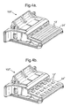
- the first embodiment of electrical connection system 100 essentially comprises three parts - first and second electrical connectors 102, which are substantially identical; and a housing 8.
- Each connector 102 has an insulating (plastics) body 1 to which an FFC (or FPC) 3 is clamped, as described in more detail below.
- the housing 8 is also formed from insulating (plastics) material and receives the connectors 102 to mate the FFCs 3.
- each connector 102 comprises a rear wall 20, a front edge 22, an upper contact surface 24, and a lower surface 26.
- the body 1 has a through bore 28 which extends in an axial direction A, and which has an outer opening 28" in the rear wall 20, and an inner opening 28' which opens adjacent the upper surface 24.
- the FFC 3 passes through the through bore 28, extends across the upper contact surface 24, is bent around the front edge 22, and is secured to the lower surface 26.
- the free end 12 of the FFC 3 is cut to be substantially T-shaped and is secured beneath a pair of hooks 4 formed in the lower surface 26. Other arrangements for securing the free end 12 of the FFC 3 to the lower surface 26 may be used.
- the FFC 3 is also secured to the body 1 by a fixation member 5 which is attached to the body 1 at the rear wall 20 by a hinge 16. After insertion of the FFC 3, the fixation member 5 is pivoted until tabs 14 on the member 5 make a snap fit in corresponding windows 15 formed in the side edges 30 of the body 1.
- the fixation member 5 also provides strain relief for the FFC 3.
- the upper contact surface 24 of the body 1 has a contact area 13, which may be separately formed (of a different material), to exert a force on the FFC 3 in a direction substantially perpendicular to the axial direction A, to increase the contact pressure on mating. As shown in Figure 4, the contact area 13 may be substantially convex in shape.
- the contact area may be formed with rows of resilient bumps 13', 13" (as shown in Figure 4a or Figure 4b respectively).
- the conductors of the portion 2 of the FFC 3 adjacent the contact area 13 are exposed for electrical connection on mating.
- Each side edge 30 of the body 1 has an axially extending rib 6.
- the lower surface 26 of the body 1 has a latch arm 7 formed therein adjacent the rear wall 20.
- the housing 8 is substantially tubular with a bore 32 extending therethrough for receiving the connectors 102.
- Axially extending slots 10 are formed in the inner surface of the housing 8 for slidably receiving the ribs 6 on the bodies 1 of the connectors 102.
- the latch arms 7 on the connector bodies 1 make a snap fit in windows 11 formed in the housing 8.
- Ribs 9 may be formed in the housing 8 to increase the strength thereof.
- one of the connectors 102 is slid into the bore 32 in the housing 8 from one end thereof, and the other connector is slid into the bore from the other end thereof but with a reversed orientation.
- the upper contact surfaces 24 of each connector 102 are adjacent and facing one another.
- the exposed conductors of the portion 2 of the FFC 3 secured to one connector 102 are therefore pushed into engagement with, and electrically connect with, the exposed conductors of the portion 2 of the FFC 3 secured to the other connector 102 due to the force exerted by the contact areas 13 on each upper contact surface 24.
- the present invention therefore provides a system 100 for electrically connecting FFCs (and FPCs) 3 without the need for electrical terminals in either of the connectors 102.
- the second embodiment of electrical connection system 200 essentially comprises two parts - an electrical connector 202; and an electrical header (housing means) 18.
- the electrical connector 202 is substantially identical to the electrical connectors 102 of Figures 1 to 4, and like parts have been given the same reference numeral.
- the electrical header 18 has a bore 34 for receiving the electrical connector 202 is a sliding fit.
- Axially extending slots 10 are formed in the inner surface of the header connector 18 for slidably receiving the ribs 6 on the connector body 1 of the electrical connector 202.
- the latch arm 7 on the connector body 1 makes a snap fit in a window 11 formed in the header 18.
- Electrical terminals 17 are secured to the header 18 and have a resilient contact surface 36 positioned in the bore 34.
- the electrical connector 202 is pushed into the bore 34 in the header 18. In the fully mated position, the exposed conductors of the portion 2 of the FFC 3 secured to the electrical connector 202 engage and electrically connect with the contact surfaces 36 of the terminals 17.
- the present invention therefore provides a system 200 for electrically connecting FFCs (and FPCs) 3 to terminals of a header without the need for electrical terminals in the electrical connector 202.
Landscapes
- Coupling Device And Connection With Printed Circuit (AREA)
Applications Claiming Priority (2)
| Application Number | Priority Date | Filing Date | Title |
|---|---|---|---|
| GB0116810 | 2001-07-10 | ||
| GBGB0116810.3A GB0116810D0 (en) | 2001-07-10 | 2001-07-10 | Electrical connection system |
Publications (1)
| Publication Number | Publication Date |
|---|---|
| EP1276174A2 true EP1276174A2 (de) | 2003-01-15 |
Family
ID=9918222
Family Applications (1)
| Application Number | Title | Priority Date | Filing Date |
|---|---|---|---|
| EP02077297A Withdrawn EP1276174A2 (de) | 2001-07-10 | 2002-06-12 | Elektrische Verbindungseinrichtung |
Country Status (3)
| Country | Link |
|---|---|
| US (1) | US6749459B2 (de) |
| EP (1) | EP1276174A2 (de) |
| GB (1) | GB0116810D0 (de) |
Cited By (2)
| Publication number | Priority date | Publication date | Assignee | Title |
|---|---|---|---|---|
| KR100655833B1 (ko) | 2005-11-14 | 2006-12-13 | 에프씨아이 아시아 테크놀로지 피티이 리미티드 | 연성 인쇄기판용 커넥터 |
| CN111211432A (zh) * | 2018-11-22 | 2020-05-29 | 矢崎总业株式会社 | 连接器 |
Families Citing this family (24)
| Publication number | Priority date | Publication date | Assignee | Title |
|---|---|---|---|---|
| US20100167561A1 (en) * | 2003-04-11 | 2010-07-01 | Neoconix, Inc. | Structure and process for a contact grid array formed in a circuitized substrate |
| US8584353B2 (en) | 2003-04-11 | 2013-11-19 | Neoconix, Inc. | Method for fabricating a contact grid array |
| US7114961B2 (en) * | 2003-04-11 | 2006-10-03 | Neoconix, Inc. | Electrical connector on a flexible carrier |
| US7244125B2 (en) | 2003-12-08 | 2007-07-17 | Neoconix, Inc. | Connector for making electrical contact at semiconductor scales |
| US7758351B2 (en) | 2003-04-11 | 2010-07-20 | Neoconix, Inc. | Method and system for batch manufacturing of spring elements |
| JP4036370B2 (ja) * | 2003-06-02 | 2008-01-23 | 日本航空電子工業株式会社 | 電気コネクタ及びその製造方法 |
| TWI309094B (en) | 2004-03-19 | 2009-04-21 | Neoconix Inc | Electrical connector in a flexible host and method for fabricating the same |
| US7332048B2 (en) * | 2004-11-17 | 2008-02-19 | The Boeing Company | Forming and bonding of flex circuits to structures |
| US7443354B2 (en) * | 2005-08-09 | 2008-10-28 | The Boeing Company | Compliant, internally cooled antenna apparatus and method |
| US7357644B2 (en) * | 2005-12-12 | 2008-04-15 | Neoconix, Inc. | Connector having staggered contact architecture for enhanced working range |
| WO2007124113A2 (en) * | 2006-04-21 | 2007-11-01 | Neoconix, Inc. | Clamping a flat flex cable and spring contacts to a circuit board |
| FR2901420B1 (fr) * | 2006-05-18 | 2016-11-25 | Axon'cable | Micro-connecteur de puissance |
| US8503941B2 (en) | 2008-02-21 | 2013-08-06 | The Boeing Company | System and method for optimized unmanned vehicle communication using telemetry |
| CN201196997Y (zh) * | 2008-03-25 | 2009-02-18 | 富士康(昆山)电脑接插件有限公司 | 电连接器组件 |
| US8393918B2 (en) * | 2008-06-11 | 2013-03-12 | Pulse Electronics, Inc. | Miniaturized connectors and methods |
| JP4678886B2 (ja) * | 2008-12-12 | 2011-04-27 | 日本航空電子工業株式会社 | 電気接続部材 |
| JP5227233B2 (ja) * | 2009-03-31 | 2013-07-03 | 矢崎総業株式会社 | Lifコネクタ |
| JP5547525B2 (ja) * | 2010-03-17 | 2014-07-16 | 矢崎総業株式会社 | 端末接続具 |
| US8840415B2 (en) * | 2011-10-05 | 2014-09-23 | Tyco Electronics Corporation | Power cable connector |
| US8641428B2 (en) | 2011-12-02 | 2014-02-04 | Neoconix, Inc. | Electrical connector and method of making it |
| US8961231B2 (en) * | 2012-12-18 | 2015-02-24 | Apple Inc. | Retention mechanisms for electrical connectors |
| US9680273B2 (en) | 2013-03-15 | 2017-06-13 | Neoconix, Inc | Electrical connector with electrical contacts protected by a layer of compressible material and method of making it |
| US10637171B1 (en) * | 2019-03-15 | 2020-04-28 | Aptiv Technologies Limited | Electrical connector |
| US20220302624A1 (en) * | 2021-03-16 | 2022-09-22 | GE Precision Healthcare LLC | Electrical connectors for medical devices |
Family Cites Families (34)
| Publication number | Priority date | Publication date | Assignee | Title |
|---|---|---|---|---|
| US3941448A (en) * | 1974-07-29 | 1976-03-02 | E. I. Du Pont De Nemours & Company | Connector block |
| GB9309096D0 (en) * | 1993-05-01 | 1993-06-16 | Gen Motors France | Electrical connector for battery terminals |
| DE19625567C2 (de) * | 1996-06-26 | 2001-02-15 | Bosch Gmbh Robert | Kraftstoff-Förderpumpe für eine Kraftstoff-Einspritzpumpe für Brennkraftmaschinen |
| US5775930A (en) * | 1996-12-13 | 1998-07-07 | General Motors Corporation | Electrical connector with locking connector position assurance member |
| US6077124A (en) * | 1997-10-10 | 2000-06-20 | Molex Incorporated | Electrical connectors for flat flexible circuitry with yieldable backing structure |
| US6071153A (en) * | 1998-02-19 | 2000-06-06 | Delphi Technologies, Inc. | Dual lock for multi-row electrical connector system |
| US6171146B1 (en) * | 1998-02-19 | 2001-01-09 | Delphi Technologies, Inc. | Repair method for dual lock multi-row electrical connector system |
| GB2334632B (en) * | 1998-02-23 | 2002-03-13 | Delphi Automotive Systems Gmbh | Two-part electrical connector |
| DE19835670A1 (de) * | 1998-08-06 | 2000-04-20 | Delphi Automotive Systems Gmbh | Dichtungsanordnung zwischen einem elektrischen Verbinder und einem elektrischen Leiter |
| DE19844693A1 (de) * | 1998-09-29 | 2000-03-30 | Delphi Automotive Systems Gmbh | Zweiteiliger elektrischer Verbinder |
| US6142813A (en) * | 1998-12-08 | 2000-11-07 | Delphi Technologies, Inc. | Electrical connector assembly |
| US6176746B1 (en) | 1999-04-29 | 2001-01-23 | Delphi Technologies, Inc. | Electrical connector housing with multi functional cover |
| US6162085A (en) * | 1999-08-19 | 2000-12-19 | Delphi Technologies, Inc. | Electrical connector assembly for jumper cable |
| US6210186B1 (en) * | 1999-09-27 | 2001-04-03 | Delphi Technologies, Inc. | Captured connector assurance component for an electrical connector |
| US6203364B1 (en) * | 1999-10-12 | 2001-03-20 | Delphi Technologies, Inc. | Electrical connector having slide clip attachment |
| US6416119B1 (en) * | 1999-10-26 | 2002-07-09 | Daimlerchrysler | Vehicle front end construction through the use of hydroformed tubes |
| US6247965B1 (en) * | 1999-12-06 | 2001-06-19 | Delphi Technologies, Inc. | Electrical connector having sealed snap-in locking cavity plugs |
| US6305957B1 (en) * | 2000-02-24 | 2001-10-23 | Delphi Technologies, Inc. | Electrical connector assembly |
| US6406307B2 (en) * | 2000-02-28 | 2002-06-18 | Delphi Technologies, Inc. | Annular electrical connector assembly |
| US6379162B1 (en) * | 2000-07-27 | 2002-04-30 | Delphi Technologies, Inc. | Electrical connector system |
| US6338651B1 (en) * | 2000-08-10 | 2002-01-15 | Delphi Technologies, Inc. | Electrical connector assembly with seal |
| US6276960B1 (en) * | 2000-08-29 | 2001-08-21 | Delphi Technologies, Inc. | Electrical power connector system |
| US6485337B2 (en) * | 2000-08-30 | 2002-11-26 | Delphi Technologies, Inc. | Electrical connector |
| US6361356B1 (en) * | 2000-10-03 | 2002-03-26 | Delphi Technologies, Inc. | Electrical connector position assurance device |
| US6533611B2 (en) * | 2000-10-03 | 2003-03-18 | Delphi Technologies, Inc. | Electrical connector assembly with secondary terminal lock |
| US6383033B1 (en) * | 2000-12-07 | 2002-05-07 | Delphi Technologies, Inc. | Side load electrical connector |
| US6565372B2 (en) * | 2001-02-27 | 2003-05-20 | Delphi Technologies, Inc. | Staged lock feature for an electrical connector assembly having a cam mating device |
| US6422881B1 (en) * | 2001-02-27 | 2002-07-23 | Delphi Technologies, Inc. | Electrical connector having a blade stabilizer |
| US6527573B2 (en) * | 2001-05-22 | 2003-03-04 | Delphi Technologies, Inc. | Slide contact electrical connector |
| US6547605B2 (en) * | 2001-07-20 | 2003-04-15 | Delphi Technologies, Inc. | Flex circuit electrical connector |
| US6494751B1 (en) * | 2001-07-20 | 2002-12-17 | Delphi Technologies, Inc. | Terminal-side locking electrical header connector |
| US6537099B2 (en) * | 2001-08-22 | 2003-03-25 | Delphi Technologies, Inc. | Tamper proof electrical connector |
| US6485318B1 (en) * | 2001-11-13 | 2002-11-26 | Delphi Technologies, Inc. | Electrical shuttle connector |
| US6508666B1 (en) * | 2002-02-08 | 2003-01-21 | Delphi Technologies, Inc. | Pass-thru electrical connector assembly |
-
2001
- 2001-07-10 GB GBGB0116810.3A patent/GB0116810D0/en not_active Ceased
-
2002
- 2002-06-12 EP EP02077297A patent/EP1276174A2/de not_active Withdrawn
- 2002-06-27 US US10/185,833 patent/US6749459B2/en not_active Expired - Fee Related
Cited By (3)
| Publication number | Priority date | Publication date | Assignee | Title |
|---|---|---|---|---|
| KR100655833B1 (ko) | 2005-11-14 | 2006-12-13 | 에프씨아이 아시아 테크놀로지 피티이 리미티드 | 연성 인쇄기판용 커넥터 |
| CN111211432A (zh) * | 2018-11-22 | 2020-05-29 | 矢崎总业株式会社 | 连接器 |
| CN111211432B (zh) * | 2018-11-22 | 2021-05-11 | 矢崎总业株式会社 | 连接器 |
Also Published As
| Publication number | Publication date |
|---|---|
| GB0116810D0 (en) | 2001-08-29 |
| US6749459B2 (en) | 2004-06-15 |
| US20030013341A1 (en) | 2003-01-16 |
Similar Documents
| Publication | Publication Date | Title |
|---|---|---|
| US6749459B2 (en) | Electrical connection system | |
| EP0572874B1 (de) | Elektrische Kontaktzunge mit doppelter Dicke | |
| CN2596605Y (zh) | 电连接器 | |
| JP4187338B2 (ja) | 電気コネクタ | |
| US6139376A (en) | Female electrical terminal | |
| EP0828315B1 (de) | Elektrischer Steckverbinder für Kabel, Montage und dazugehörige Methode | |
| EP1235301A3 (de) | Ein Steckerzusammenbau für ein Flachkabel | |
| US6589082B2 (en) | Electric connector | |
| US6068505A (en) | Electrical contact for flexible flat cable | |
| US6918798B2 (en) | Female terminal with flexible sidewalls and flat angled contacts | |
| EP0795930B1 (de) | Elektrische Aufnahmebuchse für Stift mit hoher Kontaktkraft | |
| CA1192971A (en) | Electrical connector | |
| US5888107A (en) | Male contact | |
| CN101040407A (zh) | 用于电连接器的改进锁扣件 | |
| JP2006511918A (ja) | フレキシブルケーブル電気コネクタ | |
| US6142821A (en) | Electrical connector assembly with guiding device | |
| JP2868405B2 (ja) | 雌型端子 | |
| EP0570039B1 (de) | Elektrische Anschlussklemme | |
| EP0668631B1 (de) | Zugentlastung in einer elektrischen Verbinderanordnung für Bandkabel | |
| JP2001509948A (ja) | ケーブルコネクタ | |
| US11489279B2 (en) | Connector for a flat flexible cable | |
| EP0549908B1 (de) | Elektrische Anschlussanordnung mit Anschlussverriegelungselement | |
| CA2819874C (en) | Hermaphroditic electrical connector for terminating electrical conductors | |
| US6270373B1 (en) | Connector with contact | |
| US9065209B2 (en) | Hermaphroditic electrical connector for terminating electrical conductors |
Legal Events
| Date | Code | Title | Description |
|---|---|---|---|
| PUAI | Public reference made under article 153(3) epc to a published international application that has entered the european phase |
Free format text: ORIGINAL CODE: 0009012 |
|
| AK | Designated contracting states |
Kind code of ref document: A2 Designated state(s): AT BE CH CY DE DK ES FI FR GB GR IE IT LI LU MC NL PT SE TR |
|
| AX | Request for extension of the european patent |
Free format text: AL;LT;LV;MK;RO;SI |
|
| STAA | Information on the status of an ep patent application or granted ep patent |
Free format text: STATUS: THE APPLICATION IS DEEMED TO BE WITHDRAWN |
|
| 18D | Application deemed to be withdrawn |
Effective date: 20080102 |