EP1276173A2 - Tapping connection device for flat cable - Google Patents
Tapping connection device for flat cable Download PDFInfo
- Publication number
- EP1276173A2 EP1276173A2 EP02015557A EP02015557A EP1276173A2 EP 1276173 A2 EP1276173 A2 EP 1276173A2 EP 02015557 A EP02015557 A EP 02015557A EP 02015557 A EP02015557 A EP 02015557A EP 1276173 A2 EP1276173 A2 EP 1276173A2
- Authority
- EP
- European Patent Office
- Prior art keywords
- tapping
- connection device
- flat cable
- energy transmission
- elements
- Prior art date
- Legal status (The legal status is an assumption and is not a legal conclusion. Google has not performed a legal analysis and makes no representation as to the accuracy of the status listed.)
- Withdrawn
Links
Images


Classifications
-
- H—ELECTRICITY
- H01—ELECTRIC ELEMENTS
- H01R—ELECTRICALLY-CONDUCTIVE CONNECTIONS; STRUCTURAL ASSOCIATIONS OF A PLURALITY OF MUTUALLY-INSULATED ELECTRICAL CONNECTING ELEMENTS; COUPLING DEVICES; CURRENT COLLECTORS
- H01R12/00—Structural associations of a plurality of mutually-insulated electrical connecting elements, specially adapted for printed circuits, e.g. printed circuit boards [PCB], flat or ribbon cables, or like generally planar structures, e.g. terminal strips, terminal blocks; Coupling devices specially adapted for printed circuits, flat or ribbon cables, or like generally planar structures; Terminals specially adapted for contact with, or insertion into, printed circuits, flat or ribbon cables, or like generally planar structures
- H01R12/50—Fixed connections
- H01R12/59—Fixed connections for flexible printed circuits, flat or ribbon cables or like structures
- H01R12/65—Fixed connections for flexible printed circuits, flat or ribbon cables or like structures characterised by the terminal
- H01R12/67—Fixed connections for flexible printed circuits, flat or ribbon cables or like structures characterised by the terminal insulation penetrating terminals
-
- H—ELECTRICITY
- H01—ELECTRIC ELEMENTS
- H01R—ELECTRICALLY-CONDUCTIVE CONNECTIONS; STRUCTURAL ASSOCIATIONS OF A PLURALITY OF MUTUALLY-INSULATED ELECTRICAL CONNECTING ELEMENTS; COUPLING DEVICES; CURRENT COLLECTORS
- H01R4/00—Electrically-conductive connections between two or more conductive members in direct contact, i.e. touching one another; Means for effecting or maintaining such contact; Electrically-conductive connections having two or more spaced connecting locations for conductors and using contact members penetrating insulation
- H01R4/24—Connections using contact members penetrating or cutting insulation or cable strands
- H01R4/2404—Connections using contact members penetrating or cutting insulation or cable strands the contact members having teeth, prongs, pins or needles penetrating the insulation
- H01R4/2406—Connections using contact members penetrating or cutting insulation or cable strands the contact members having teeth, prongs, pins or needles penetrating the insulation having needles or pins
Definitions
- the invention relates to connection devices for tapping a flat cable having energy transmission cores, which tap elements with a contact tip to penetrate the flat cable jacket and / or the core insulation and to contact the respective energy transmission wire exhibit.
- connection devices are in the prior art known with which continuous flat cable can be tapped without stripping and separation.
- the tapping elements are U-shaped Insulation clamps are formed, each of which Pick up the contacting wire between the U-legs (see e.g. DE 27 36 244 A1).
- Such connection devices are particularly widespread for tapping data cables found.
- connection devices In another known type, namely the connection devices of the type mentioned at the beginning is the tap element however equipped with a contact tip.
- this contact tip is centered in the for tapping certain wire pierced and through the flat cable jacket and / or the wire insulation is pressed.
- Such Connection device is for example from DE-AS 2 206 Known in 187.
- the tapping elements are as with a Contact tip provided screws formed. The stabbing the contact tip in the flat cable jacket and / or the Wire insulation for the purpose of contacting the relevant energy transmission wire is done by screwing in the concerned Anzapfschraube. Similar, on the use of tap screws based solutions are from EP 0 877 445 A2 and DE 297 06 750 U1 known.
- connection device in the manner of a socket
- coupling devices e.g. a relay for Switching the power current
- connection devices for stripping and eye-free tapping of cables have advantages (especially with regard to the simple and quick installability), they were able to for power transmission lines not compared to the conventional installation technology (in which the cables must be separated and stripped) in general push through.
- the invention provides a connection device for tapping an energy transmission core having flat cable ready.
- the connection device assigns tap elements with a contact tip Penetration of the flat cable jacket and / or the wire insulation and to contact the respective energy transmission wire on.
- the contact tip forms a flat angle of at least 70 °, in particular at least 80 °.
- the invention relates to a connection device for tapping an energy transmission core having flat cable.
- the connection device has tapping elements with a contact tip for penetration the flat cable jacket and / or the wire insulation and to contact the respective energy transmission wire on.
- the contact tip has a pointed area and in a flank area different angles. Here is the Angles in the flank area are flatter than those in the tip area.
- FIG 1 is first a flat cable 1 with five in one Level energy transmission wires 2 shown.
- the two external wires 2 as protective earth conductor (PE) and neutral conductor (N) and the three inside Cores 2 as the three conductors (L1, L2, L3) of a three-phase system (e.g. a 380 volt three-phase system for Europe or a 190 volt three-phase system for the USA).
- the Cores 2 are each from a conductor 3, generally one Strand, and a wire insulation 4 built.
- the single ones Veins 2 are embedded in a jacket 5, which defines the flat cable geometry, and in particular the individual wires 2 in a precisely defined position relative fixed to the outside of the cable.
- the flat cable 1 is with longitudinal notches (or, if not shown Embodiments, equipped with surveys), namely such that the flat cable 1 has no 180 ° rotational symmetry (i.e. the cross-sectional shape against twisting is not invariant by 180 ° around the longitudinal axis).
- This forms a "coding" which ensures that when in use a complementary connection device, the cable only one defined location can be tapped.
- this coding formed that 2 notches in the area between three of the wires 6 are provided, a corresponding notch an outer end (between the wires PE and L1), however is missing.
- the wire insulation 4 and / or the jacket 5 are i.a. made of a thermoplastic.
- Embodiments are direct conductors - So without separate wire insulation - embedded in the jacket. In these embodiments, therefore, has cable insulation the functions of wire insulation and the cable jacket.
- the hardness is first shown schematically in FIG. 2 one usually for core insulation 4 and Sheath 5 used thermoplastic material shown as a function of temperature.
- the core insulation 4 essentially made of polyethylene
- the jacket 5 is constructed essentially of PVC his; a relationship corresponding to FIG. 2 also applies to various networked plastics, which are alternative for the Core insulation 4 and / or the jacket 5 are used can.
- Fig. 2 shows, the hardness of such increases Plastic material with increasing temperature, whereby this decrease - depending on the plastic considered - for example concave (as shown in Fig. 2), convex, or can be concave / convex in sections.
- a flat cable The present type becomes ambient temperature on the one hand (e.g.
- 3 shows a schematic cross-sectional view a flat cable 1 in operation, with lines same hardness 7 (so-called iso hardness lines) are.
- iso hardness lines lines same hardness 7
- 3 shows three iso-hardness lines 7a, 7b and 7c, which have correspondingly marked hardnesses correspond in Fig. 2.
- the furthest inside is the Iso hardness line 7a with the smallest, in the transition area hardness to flow.
- Fig. 3 particularly illustrates that the cable jacket 5 in the area the connection level of two conductors 3 is relatively soft while he is leading to the outside from a conductor 3 Range reached greater hardness relatively soon.
- the inventor recognized that due to this spatial hardness course a shift of the ladder 3 in the conductor level only relatively low elastic Restoring forces (because the conductor 3 essentially in the low hardness range) while a shift across to it, i.e. outwards, to higher ones elastic restoring forces (because then the conductor 3 against the harder remaining elastic part of the Jacket 5 is pressed.
- the tapping elements are relatively acute-angled Contact tips equipped, which lead to the fact that when pressing the contact tip into the wire of the conductor 3 these essentially to the side (i.e. at the ladder level) is pushed apart. The displaced strand deformed the surrounding plastic material, so that this is the Braid back - i.e. against the tap element - presses. This lateral displacement goes in that area of the Cable sheath that for the reasons given above the elastic restoring forces is rather unfavorable.
- heating and cooling cycles With each of these cycles can because of the approach to the flow area the elastic Restoring forces of the cable sheath become somewhat lower, so that possibly after a long period of operation contact problems occur at the tap.
- the inventor has recognized that it is therefore advantageous to tap the conductor 3 so that the wire tends towards the outside rather than the side Direction is shifted.
- FIG. 4 relating to the first aspect of the invention forms the contact tip 12 'in a tapping element 11' a flat tip angle 13 of at least 70 °, in particular at least 80 °.
- the tap element 11 ' has, for example the shape of a cylindrical pin.
- the tap element formed as a screw the part shown in Fig. 4 then corresponds essentially to the screw tip.
- the Point angle 13 ' is defined as the angle that viewed in cross section according to FIG. 4, the two boundary lines the tip 12 'together. At the in 4 example, this angle is approximately 100 °.
- the contact tip is therefore advantageous formed so that they are in a pointed area and has different angles in a flank area, where the angle in the flank area is flatter than in the pointed area is.
- the flatter angle need not be at least 70 °; rather, the training is with two different ones Angles then also advantageous in the sense of a reduced lateral displacement of the strand if the flatter Angle is less than 70 °.
- the flatter angle i.e. the angle in Flank area, or, at several angles, the flattest Angle in the flank area again at least 70 °, in particular is at least 80 ° as defined above.
- FIG. 5 11 An embodiment of a tapping element shown in FIG. 5 11 "has a contact tip 12" whose angle increases from the tip area to the flank area in one step (In other, not shown embodiments further angular gradations may be provided).
- the contact tip 12 has the shape of an acute angle Dorns 14 ", which is centered on a flat-angle rotation cone 15 ", which forms the flank area is.
- the tip angle 16 "of the mandrel 14" is, for example 30 °, the flatter angle 13 "of the flank area
- 15 is, for example, at least 50 ° in which 5, for example, approximately 100 °.
- the contact tip 12 "' is designed so that the apex angle from the apex to the flanks steadily increasing.
- the top 12 "'thus a concave curved (e.g. parabolic) outer shape.
- the tip angle 16 ′′ for example 20 °
- the angle 13 "' is defined as, for example Angle at which the cross-sectional view each at the extreme point of the tip 12 "' Cut tangents.
- the width D of the tapping elements 11 ', 11 ", 11"' above the Tip 12 ', 12 “, 12"' transverse to the longitudinal direction of the cable is advantageous greater than or equal to the diameter d of the conductor 3 selected. This is illustrated in FIGS. 4, 5 and 6.
- Such a wide design of the tapping elements contributes to avoid lateral displacement of the strand of the Head 3 and to achieve a possible in the tap direction displacement of the tapping elements 11 ', 11 ", 11 “'.
- the in Fig. 7 embodiment shown is particularly advantageous.
- the length of the tapping element 11 is selected so that that the outer end of the contact tip 12 on the one hand penetrates as deep as possible into the conductor 3, but on the other hand not on the opposite side of the indentation side Leader comes out again.
- the length of the tapping element 11 is advantageously measured not at the nominal position of the conductor 3 in Flat cable, but at the position that the conductor 3 actually in the assembled state of the connection device occupies. Due to that caused by the tap element 11 The pressure of the conductor 3 is namely in the flat cable in the direction of insertion of the tapping element 11 shifted.
- tapping element 11 is straight chosen so that the outer end of the tip 12 in the normal position would exit from head 3 because of actual displacement of the conductor 3 but does not emerge. In other words, the end of the tip 12 in the area that in Fig. 7 between the dashed and the solid line.
- the above-mentioned configurations of the contact tips can are used for such connection devices, where the tap elements are equipped with a thread are so that they are screwed in individually the flat cable can be pressed in.
- connection devices in which the tapping elements can be pressed into the flat cable without rotation.
- All tap elements are embodied simultaneously pressed together into the flat cable. This is the tapping of a multi-core cable in one Operation possible.
- a flat cable to be tapped can also be designed as a hybrid cable.
- 8 is an example of such a hybrid cable 21 shown, which next to Energy transmission cores 2 also a shielded symmetrical Pair line with two data transmission cores 22a, 22b having.
- the data transmission lines run 22a, 22b not twisted.
- FIG. 9 shows an example of a tap element 31 for a Data transmission line 22 of a shielded double line.
- the heating phenomena discussed above occur in data transmission wires not because the signal currents flowing here serve essentially only a potential adjustment and are therefore negligibly small. For warming because of ohmic losses it does not come.
- tapping of a data transmission conductor therefore leads to displacement sufficient elastic only in the lateral direction Restoring forces.
- a flat-angled education the contact tip 32 could be unfavorable here, since one such a flat tip, the shield 28 rather at Piercing the wire insulation of a data transmission wire would be drawn in, which could lead to a short circuit.
- Advantageous is therefore the contact tip of the data transmission tap 31 more pointed than that (12 ') of the energy transmission wire tapping elements 11 'trained.
- connection devices 10 to 14 are preferred embodiments of connection devices described in more detail. First some more general comments follow.
- the connector is trained so that they are connected to a live Flat cable can be mounted.
- those Parts that are under tension during assembly Flat cables are live, safe to touch designed.
- live Parts, e.g. the tapping elements, facing away from the cable Side of the connector only by such small holes (e.g. for inserting plug contacts) accessible are that according to the usual safety standards adequate security against contact with a Finger is guaranteed.
- Touching parts with a tool such as the Case is when the tapping elements as electrically conductive Contact screws are designed and for tapping the cable be screwed in with a screwdriver).
- the Possibility of tapping an energy transmission cable is under tension especially in the commercial area Building installations are an advantage because of the necessity the shutdown of parts of the supply network i.e. associated with high costs (e.g. due to loss of production) is.
- the several tap elements of the connection device together pressed into the flat cable.
- the tapping elements are advantageous for this firmly arranged in a tap part, whereby the common Press in the tap elements by pressing on this tap part on a complementary base part - with that already inserted flat cable - can be done.
- connection device serves, for example, a branch line to the - generally continuous - flat cable connect and / or directly to the flat cable Device, such as a switch, a sensor, an actuator etc. to arrange.
- the branch line or device can be electrically and mechanically fixed with the connection device be connected.
- connection device can be interface-like be constructed.
- 10-14 is, for example, the tap part as a socket trained in which a complementary plug can be inserted is.
- This connector carries the branch line or the device.
- the interface-like training shown has two advantages: (i) the assembly of the connector is easier because the connection of the branch line or the device on the not yet inserted Plug - and thus removed from the flat cable can; this also allows pre-assembly of Connector with branch line or connector with a device; (ii) One and the same type of tap part can be used for various objects to be connected (branch lines, different types of devices) can be used.
- the plug preferably has plug contacts on which is advantageously concentric with the tapping elements of the tap element housing part are arranged.
- the tapping elements are on the side facing away from the cable socket-shaped, so that the plug contacts when Insert the plug into the socket directly into the socket-like tapping elements are inserted.
- a pair of plug-contact sockets for a ground or earth connection is preferably designed so that when Insert the plug into the socket first a mass or earth connection, and only then connections to the live conductors.
- a ground or earth connection serving plug contact slightly longer than the other plug contacts be executed.
- connection device is for connecting a branch line advantageously equipped with spring clips. This applies equally for embodiments with socket-plug training are (the spring clips are then arranged in the plug), as for not trained as a socket and plug Embodiments (the latter are the spring clips for example on the tap element housing part ) Are arranged. Equipping with spring clips allows one quick assembly; spring clips are also regarding the contact retention advantageous.
- connection device is advantageously designed such that the branch line can be led out of it on both sides is, for example parallel to the flat cable level in the longitudinal direction of the cable and across it.
- Such a two-sided Feasibility of the branch line is advantageous both in such embodiments as sockets and plugs are trained, as well as those in which this is not the case.
- connection device with a branch line in the connection area of the branch line between the connection points for the individual wires of the branch line Walls to extend the creepage distance.
- the walls for crawl lengthening in the case of the socket-plug design, for example in the plug are arranged, for example, in the other type are arranged on the tap part.
- Connection devices for tapping hybrid cables are advantageously have in the connection area of the Branch line between the connection points of the energy transmission wires and one of the data transmission wires Partition on the electrically conductive for shielding can be and possibly grounded or with the shield the data line of the hybrid cable be electrically connected can.
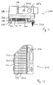
- FIG. 10 shows a cross-sectional view of a preferred connection device 100 not yet assembled.
- the connection device 100 is composed of three assemblies, which in assembled, so to speak form three "floors". It this is a base part 140, a tap part 160 and a plug part 180, which are not yet shown in FIG. 10 assembled state together with one to be contacted Hybrid flat cable 21 (Fig. 8) are shown.
- the Base part 140 and tap part 160 are intended to be assembled Condition the cable 21 in a precisely defined position between to record oneself.
- the base part 140 has a equipped in the longitudinal direction continuous receptacle 141, which have longitudinal centering ribs on the floor 142 and has also longitudinal side walls 142 is limited.
- the centering ribs 142 engage in complementary notches 6 in the cable 21 and set hereby, together with the side walls 143, its exact Position the flat cable securely. Because of their non-axisymmetric Arrangement prevent the centering ribs 142 also a wrong insertion of the cable 21; she thus also have a coding function.
- Appropriate Centering ribs can also be located in the tapping part 160 (not shown).
- the side walls 143 face outside one or more longitudinal locking lugs each 144 on. Complementary to this are on the tapping part 160 Locking undercuts (not shown) so that the two parts (140, 160) of the tap position with each other can be locked.
- the tap part 160 comprises a tap element receiving plate 161 with two longitudinal transverse walls 162, which the Embrace side walls 143 of base part 140 and said, to the locking lugs 144 complementary locking undercuts (not shown in Fig. 10).
- the tap element receiving plate 161 In the tap element receiving plate 161 are electrically conductive Tapping elements 11 fixedly arranged which Cable 21, so in the of the mounting plate 161 and Cross walls 162 extend space formed.
- the tap elements 11, 31 are exactly in the middle of the one to be tapped Core 2, 22 arranged. Regarding their length refer to the comments on FIG. 7.
- the tops of the Tap elements 11, 31 are only shown schematically in FIG. 10; more precise views of preferred training are shown in Figs. 4 to 6 and 9.
- the tap elements 11, 31 are arranged offset in the longitudinal direction of the cable, and although preferably along an oblique to the longitudinal direction of the cable straight lines.
- the tapping elements 11, 31 are through the receiving plate 141 passed and are to that of the flat cable 21 opposite side formed as sockets 164.
- transverse walls 162 and the side walls 143 cover even before the tips of the tapping elements 11 Make contact with the conductors 3 of the flat cable; this it makes it difficult, for example with a tool, the tapping elements 11 between cable 3 and mounting plate 161, if they are already under tension (however in spite of this measure, the tapping elements remain possible 11 from the front e.g. with one tool to touch).
- the plug part 180 is on the plug side with pins 181 equipped, which to the sockets 164 of the tapping part 160 are complementary. (The data transfer taps 31 belonging pins are in turn in front of the drawing level and are therefore not shown.) Protective earth conductor (PE) pin 181a to be assigned somewhat longer than the other pins 181b. As a result, when the plug part 180 is inserted into the the tapping part 160 forming the complementary bushing initially made an electrical protective earth connection before there is a connection with the other conductors.
- PE protective earth conductor
- Branch line to connector 180 are with the pins 181 connected spring clips 182 are provided. This are in a cavity in the embodiment of FIG. 10 arranged of the plug part 180, which - apart from from the possibility of individual wires through wire bushings 183 to insert - only from the plug side of the plug part 180 is accessible after removing a base plate 184.
- the branch line is connected through a cable duct 185 with strain relief in the plug part 180 introduced.
- the wire to be connected occasionally led through the relevant lead bushing 183 and with the bottom plate 184 removed using the Spring clip 182 connected to the relevant pin 181.
- the spring clamp 182 e.g.
- Fig. 10 is only one of two different line bushings 185, the one that an exit of the branch line transversely to the longitudinal direction of the cable allowed.
- Fig. 11 even closer is explained in the preferred embodiments yet another implementation is provided, which one Leading out of the branch line in the longitudinal direction of the cable allowed.
- the base part 140, the tapping part 160 and the plug part 180 are made of insulating plastic, apart from that from the electrically conductive tapping elements 11, 31, pins 181 and spring clips 182.
- Fig. 11 shows a side view of another preferred Embodiment of a connection device 200 to which the 10 above also applies, but this is true in some details of the embodiment according to FIG. 10 different. It is an assembled side view State of base part 240 and tap part 260 with plug part 280 attached. In the present side view are next to the tap elements 11 for the energy transmission wires also the tapping elements 31 for the data transmission wires visible (so that the tapping elements 11, 31 are not covered by the flat cable, FIG. 11 shows a view without flat cable; just for clarity such is shown in dashed lines. In Fig. 11 are in addition to the locking lugs 244 on the base part 240 complementary locking undercuts 266 on the tapping part 260 to see.
- connection device 200 is suitable, avoiding any force on the continuous flat cable 21 relatively heavy devices or branch lines subject to tensile loads take.
- the second line bushing 285 seen in the longitudinal direction of the cable.
- the 11 have the line bushings two openings (shown 285a and 285b) on, of which the first larger one to carry out an energy transmission branch line and the second, smaller, for Implementation of a separate data transmission branch line serves.
- connection device 200 from FIG. 11 in Top view.
- the top view of the tap portion 260 shows the arrangement of FIGS Sockets 264 - and thus the tapping elements 11, 31 along an oblique straight line. Because of the equidistant Arrangement of the wires in the cable 21 are also the tapping elements 11, 31 arranged equidistant, with a corresponding the inclined arrangement increased distance. An im Cable 21 present additional space between the energy and data transmission cores 2, 22 are reflected in one accordingly increased distance between the concerned Power transmission tapping element 11 and the adjacent one Data transmission tap 31 reflected.
- connector 280 has one removable cover 286 (Fig. 11). 14 shows a plan view the connector part 250 with the cover 286 removed.
- the Connection of the branch conductors here with screw terminals 282.
- walls 287 for extending the creepage distance provided a guide at the same time for the single wires connected to screw terminals 282 the branch line.
- an intermediate wall 288 is provided, which may be made of conductive Material can be made and grounded.
- connection device 200 Because the room is beyond the sloping connecting straight line terminals 282 not for connecting the branch line needed, it is possible to choose the appropriate one Corner of the connecting device 200, so to speak "to cut off". Accordingly, the three parts have 240, 260 and 280 of the connection device 200 the basic form of a Rectangle approximately diagonally halfway along the side clipped corner.
- connection devices for tapping flat cables with energy transmission wires which on the one hand is simple, fast and are securely mountable, and on the other hand in terms of Contact retention, even after long use under relative high currents are optimized.
Landscapes
- Coupling Device And Connection With Printed Circuit (AREA)
- Multi-Conductor Connections (AREA)
Abstract
Description
Die Erfindung betrifft Anschlußvorrichtungen zum Anzapfen eines Energieübertragungsadern aufweisenden Flachkabels, welche Anzapfelemente mit einer Kontaktspitze zum Durchdringen des Flachkabelmantels und/oder der Aderisolation und zum Kontaktieren der jeweiligen Energieübertragungsader aufweisen.The invention relates to connection devices for tapping a flat cable having energy transmission cores, which tap elements with a contact tip to penetrate the flat cable jacket and / or the core insulation and to contact the respective energy transmission wire exhibit.
Im Stand der Technik sind verschiedene Typen von Anschlußvorrichtungen bekannt, mit denen durchlaufende Flachkabel abisolierfrei und auftrennungsfrei angezapft werden können.Various types of connection devices are in the prior art known with which continuous flat cable can be tapped without stripping and separation.
Bei einem bekannten Typ sind die Anzapfelemente als U-förmige Schneidklemmen ausgebildet, welche jeweils die zu kontaktierende Ader zwischen den U-Schenkeln aufnehmen (siehe z.B. DE 27 36 244 A1). Solche Anschlußvorrichtungen haben insbesondere zum Anzapfen von Datenkabeln weite Verbreitung gefunden.In a known type, the tapping elements are U-shaped Insulation clamps are formed, each of which Pick up the contacting wire between the U-legs (see e.g. DE 27 36 244 A1). Such connection devices are particularly widespread for tapping data cables found.
Bei einem weiteren bekannten Typ, nämlich den Anschlußvorrichtungen der eingangs genannten Art, ist das Anzapfelement hingegen mit einer Kontaktspitze ausgerüstet. Im allgemeinen wird diese Kontaktspitze mittig in die zum Anzapfen bestimmte Ader eingestochen und durch den Flachkabelmantel und/oder die Aderisolation gedrückt. Eine derartige Anschlußvorrichtung ist beispielsweise aus der DE-AS 2 206 187 bekannt. Hierbei sind die Anzapfelemente als mit einer Kontaktspitze versehene Schrauben ausgebildet. Das Einstechen der Kontaktspitze in den Flachkabelmantel und/oder die Aderisolation zwecks Kontaktierung der betreffenden Energieübertragungsader erfolgt durch Hineindrehen der betreffenden Anzapfschraube. Ähnliche, auf der Verwendung von Anzapfschrauben beruhende Lösungen sind aus der EP 0 877 445 A2 und DE 297 06 750 U1 bekannt. Gemäß der Lehre dieser beiden Veröffentlichungen folgt der Anschluß von Abzweigleitern mit Hilfe von Federzugklemmen. Aus der EP 0 665 608 A2 ist schließlich eine, ebenfalls auf Anzapfschrauben beruhende Lösung bekannt, welche zum Kontaktieren eines Hybrid-Flachkabels (d.h. eines Kabels, welches Energieübertragungs- und Datenübertragungsadern enthält) ausgebildet ist. Aus der letztgenannten Druckschrift ist es auch bekannt, die Anschlußvorrichtung nach Art einer Steckdose auszugestalten, in welche ein Stecker mit einer Abzweigleitung und ggf. Ankopplungseinrichtungen (z.B. ein Relais zum Schalten des Leistungsstroms) einsteckbar ist.In another known type, namely the connection devices of the type mentioned at the beginning is the tap element however equipped with a contact tip. In general this contact tip is centered in the for tapping certain wire pierced and through the flat cable jacket and / or the wire insulation is pressed. Such Connection device is for example from DE-AS 2 206 Known in 187. Here, the tapping elements are as with a Contact tip provided screws formed. The stabbing the contact tip in the flat cable jacket and / or the Wire insulation for the purpose of contacting the relevant energy transmission wire is done by screwing in the concerned Anzapfschraube. Similar, on the use of tap screws based solutions are from EP 0 877 445 A2 and DE 297 06 750 U1 known. According to the teaching of this both publications are followed by the connection of branch conductors with the help of spring clamps. From EP 0 Finally, 665 608 A2 is one, also on tapping screws based solution known to contact a hybrid flat cable (i.e. a cable that transmits energy and contains data transmission wires) is. It is also from the latter publication known, the connection device in the manner of a socket To design, in which a connector with a branch line and, if necessary, coupling devices (e.g. a relay for Switching the power current) can be inserted.
Aus anderen Druckschriften ist es bekannt, statt Anzapfschrauben dornartige Anzapfelemente zu verwenden, die ohne Drehung in das Flachkabel eingedrückt werden. Ein Vorteil dieser Lösung besteht darin, daß das Eindrücken von Dornen in der Regel schneller vorgenommen werden kann als das Eindrehen von Schrauben. Eine schnellere Installierbarkeit ist insbesondere bei solchen Konstruktionen gegeben, bei denen mehrere, den verschiedenen Adern zugeordnete Anzapfdorne gleichzeitig in das Flachkabel eindrückbar sind. Hierzu sind beispielsweise die mehreren Dorne gemeinsam fest auf einer Druckplatte angeordnet. Statt mehrere Anzapfschrauben einzudrehen ist bei diesen Anschlußvorrichtungen nur noch ein Arbeitsgang erforderlich, nämlich das Aufdrücken dieser Druckplatte auf das Flachkabel. Derartige Anschlußvorrichtungen sind beispielsweise aus DE 197 39 741 A1, EP 0 817 315 A1 und US-Patentschrift 5 453 020 bekannt.It is known from other publications instead of tapping screws to use thorn-like tapping elements without Be pressed into the flat cable. An advantage this solution is that the indentation of thorns can usually be done faster than screwing of screws. It is faster to install given in particular in those constructions in which several tapping pins assigned to the different wires can be pressed into the flat cable at the same time. For this for example, the multiple mandrels are fixed together arranged a pressure plate. Instead of several tap screws It is only necessary to screw in these connecting devices one operation is required, namely pressing it on Pressure plate on the flat cable. Such connection devices are for example from DE 197 39 741 A1, EP 0 817 315 A1 and U.S. Patent 5,453,020.
Obwohl die genannten Anschlußvorrichtungen zum abisolierund auftrennungsfreien Anzapfen von Kabeln augenfällige Vorteile aufweisen (vor allem hinsichtlich der einfachen und schnellen Installierbarkeit), konnten sie sich bis heute für Energieübertragungsleitungen nicht gegenüber der herkömmlichen Installationstechnik (bei welcher die Leitungen aufgetrennt und abisoliert werden müssen) allgemein durchsetzen.Although the mentioned connection devices for stripping and eye-free tapping of cables Have advantages (especially with regard to the simple and quick installability), they were able to for power transmission lines not compared to the conventional installation technology (in which the cables must be separated and stripped) in general push through.
Die Erfindung stellt gemäß einem ersten Aspekt eine Anschlußvorrichtung zum Anzapfen eines Energieübertragungsadern aufweisenden Flachkabels bereit. Die Anschlußvorrichtung weist Anzapfelemente mit einer Kontaktspitze zum Durchdringen des Flachkabelmantels und/oder der Aderisolation und zum Kontaktieren der jeweiligen Energieübertragungsader auf. Die Kontaktspitze bildet einen flachen Winkel von wenigstens 70°, insbesondere wenigstens 80°.According to a first aspect, the invention provides a connection device for tapping an energy transmission core having flat cable ready. The connection device assigns tap elements with a contact tip Penetration of the flat cable jacket and / or the wire insulation and to contact the respective energy transmission wire on. The contact tip forms a flat angle of at least 70 °, in particular at least 80 °.
Gemäß einem zweiten Aspekt betrifft die Erfindung eine Anschlußvorrichtung zum Anzapfen eines Energieübertragungsadern aufweisenden Flachkabels. Die Anschlußvorrichtung weist Anzapfelemente mit einer Kontaktspitze zum Durchdringen des Flachkabelmantels und/oder der Aderisolation und zum Kontaktieren der jeweiligen Energieübertragungsader auf. Die Kontaktspitze hat in einem spitzen Bereich und in einem Flankenbereich unterschiedliche Winkel. Dabei ist der Winkel im Flankenbereich flacher als derjenige im Spitzenbereich.According to a second aspect, the invention relates to a connection device for tapping an energy transmission core having flat cable. The connection device has tapping elements with a contact tip for penetration the flat cable jacket and / or the wire insulation and to contact the respective energy transmission wire on. The contact tip has a pointed area and in a flank area different angles. Here is the Angles in the flank area are flatter than those in the tip area.
Die Erfindung wird nun anhand von bevorzugten beispielhaften Ausführungsformen und der angefügten beispielhaften Zeichnung näher erläutert. In der schematischen Zeichnung zeigen:
- Fig. 1
- eine Querschnittsansicht eines Flachkabels mit Energieübertragungsadern;
- Fig. 2
- einen Funktionszusammenhang zwischen der Härte der üblicherweise bei solchen Kabeln verwendeten Isolations- und Mantelmaterialien und der Temperatur;
- Fig. 3
- eine Querschnittsansicht des Flachkabels von Fig. 1, in welches Kurven gleicher Härte (Isohärtekurven) eingezeichnet sind;
- Fig. 4
- eine Querschnittsansicht eines Anzapfelements mit einer Kontaktspitze, die einen einheitlichen flachen Winkel bildet;
- Fig. 5
- eine Querschnittsansicht eines Anzapfelements mit einer Kontaktspitze, welche zwei abgestufte Winkel aufweist;
- Fig. 6
- eine Querschnittsansicht eines Anzapfelements mit einer Kontaktspitze, welche im Spitzenbereich konvex gekrümmt ausgebildet ist;
- Fig. 7
- eine Querschnittsansicht eines Ausschnitts eines Flachkabels im angezapften Zustand;
- Fig. 8
- eine Querschnittsansicht eines Flachkabels mit Datenteil (sog. Hybridkabel);
- Fig. 9
- ein Anzapfelement zum Kontaktieren einer abgeschirmten Datenübertragungsader des Kabels gemäß Fig. 8;
- Fig. 10
- eine Querschnittsansicht einer Anschlußvorrichtung mit einem Flachkabel gemäß Fig. 8, in noch nicht montiertem Zustand;
- Fig. 11
- eine Seitenansicht der Anschlußvorrichtung von Fig. 10 in montiertem Zustand.
- Fig. 12
- eine Draufsicht auf ein Basisteil der Anschlußvorrichtung von Fig. 11;
- Fig. 13
- eine Draufsicht auf ein Anzapfteil der Anschlußvorrichtung von Fig. 11;
- Fig. 14
- eine Draufsicht auf ein Steckerteil der Anschlußvorrichtung von Fig. 11, ohne Deckel.
- Fig. 1
- a cross-sectional view of a flat cable with energy transmission wires;
- Fig. 2
- a functional relationship between the hardness of the insulation and sheath materials commonly used in such cables and the temperature;
- Fig. 3
- a cross-sectional view of the flat cable of Figure 1, in which curves of the same hardness (iso hardness curves) are drawn.
- Fig. 4
- a cross-sectional view of a tap element with a contact tip that forms a uniform flat angle;
- Fig. 5
- a cross-sectional view of a tap element with a contact tip having two stepped angles;
- Fig. 6
- a cross-sectional view of a tap element with a contact tip, which is convexly curved in the tip region;
- Fig. 7
- a cross-sectional view of a section of a flat cable in the tapped state;
- Fig. 8
- a cross-sectional view of a flat cable with data part (so-called. Hybrid cable);
- Fig. 9
- a tap element for contacting a shielded data transmission wire of the cable according to FIG. 8;
- Fig. 10
- a cross-sectional view of a connection device with a flat cable according to FIG 8, in the not yet assembled state.
- Fig. 11
- a side view of the connecting device of Fig. 10 in the assembled state.
- Fig. 12
- a plan view of a base part of the connecting device of Fig. 11;
- Fig. 13
- a plan view of a tapping part of the connecting device of Fig. 11;
- Fig. 14
- a plan view of a plug part of the connecting device of Fig. 11, without a lid.
In den Figuren tragen funktionsgleiche Teile zum Teil gleiche oder sich um eine Hunderterstelle oder Apostrophe unterscheidende Bezugszahlen.In the figures, parts that have the same function have the same parts or differing by hundreds or apostrophes Reference numerals.
In Figur 1 ist zunächst ein Flachkabel 1 mit fünf in einer
Ebene verlaufenden Energieübertragungsadern 2 gezeigt. Bei
einem solchen Flachkabel 1 können beispielsweise die beiden
außen liegenden Adern 2 als Schutzerde-Leiter (PE) und Neutralleiter
(N) geschaltet sein, und die drei innen liegenden
Adern 2 als die drei Leiter (L1, L2, L3) eines Drehstromsystems
(z.B. eines 380-Volt-Drehstromsystems für Europa
oder eins 190-Volt-Drehstromsystems für USA). Die
Adern 2 sind jeweils aus einem Leiter 3, im allgemeinen einer
Litze, sowie einer Aderisolation 4 aufgebaut. Die einzelnen
Adern 2 sind in einem Mantel 5 eingebettet, welcher
die Flachkabelgeometrie definiert, und insbesondere die
einzelnen Adern 2 in einer genau definierten Position relativ
zum Kabeläußeren fixiert. Das Flachkabel 1 ist mit
längs verlaufenden Einkerbungen (oder, bei nicht gezeigten
Ausführungsformen, mit Erhebungen) ausgerüstet, und zwar
derart, daß das Flachkabel 1 keine 180°-Drehsymmetrie hat
(d.h., daß die Querschnittsform gegenüber einer Verdrehung
um 180° um die Längsachse nicht invariant ist). Dies bildet
eine "Kodierung", welche sicherstellt, daß bei Verwendung
einer komplementären Anschlußvorrichtung das Kabel nur einer
definierten Lage angezapft werden kann. Bei dem in Figur
1 dargestellten Beispiel ist diese Kodierung dadurch
gebildet, daß im Bereich zwischen drei der Adern 2 Einkerbungen
6 vorgesehen sind, eine entsprechende Einkerbung an
einem äußeren Ende (zwischen den Adern PE und L1) jedoch
fehlt. Die Aderisolationen 4 und/oder der Mantel 5 sind
i.a. aus einem thermoplastischen Kunststoff gefertigt. Bei
(nicht gezeigten) Ausführungsformen sind die Leiter direkt
- also ohne gesonderte Aderisolationen - in den Mantel eingebettet.
Bei diesen Ausführungsformen hat also eine Kabelisolation
die Funktionen von Aderisolationen und des Kabelmantels.In Figure 1 is first a flat cable 1 with five in one
Level
Um zur Erfindung zu gelangen, hat der Erfinder erkannt, daß bei der Anzapfung derartiger Flachkabel Probleme im Zusammenhang mit Kabelerwärmung auftreten können. Grundsätzlich sollte zur Erzielung eines dauerhaften elektrischen Kontakts zwischen zwei Leitern, die nicht stoffschlüssig (z.B. durch Löten) verbunden sind, ein dauerhafter Andruck herrschen. Es wurde erkannt, daß in diesem Zusammenhang die Kabelerwärmung eine wichtige Rolle spielen kann.In order to arrive at the invention, the inventor recognized that Problems related to the tapping of such flat cables can occur with cable heating. in principle should make permanent electrical contact between two conductors that are not cohesive (e.g. by soldering), there is a permanent pressure. It was recognized that in this context cable heating can play an important role.
Zur Erläuterung ist zunächst in Fig. 2 schematisch die Härte
eines üblicherweise für die Aderisolierung 4 und den
Mantel 5 verwendeten thermoplastischen Kunststoffmaterials
als Funktion der Temperatur dargestellt. Beispielsweise
können die Aderisolierung 4 im wesentlichen aus Polyethylen,
und der Mantel 5 im wesentlichen aus PVC aufgebaut
sein; ein Fig. 2 entsprechender Zusammenhang gilt auch für
verschiedene vernetzte Kunststoffe, die alternativ für die
Aderisolierung 4 und/oder den Mantel 5 Verwendung finden
können. Wie Fig. 2 zeigt, nimmt die Härte eines derartigen
Kunststoffmaterials mit steigender Temperatur ab, wobei
diese Abnahme - je nach betrachtetem Kunststoff - beispielsweise
konkav (wie in Fig. 2 gezeigt), konvex, oder
abschnittsweise konkav/konvex verlaufen kann. Ein Flachkabel
der vorliegenden Art wird einerseits Umgebungstemperatur
(z. B. Zimmertemperatur) annehmen, wenn keine oder nur
geringe Ströme fließen), und wird sich andererseits bei
Stromfluß aufgrund der ohmschen Verluste in den Leitern 3
auf eine relativ hohe Betriebstemperatur erwärmen. Entsprechend
werden, wie in Figur 2 gezeigt ist, die Aderisolierung
4 und der Mantel 5 bei Umgebungstemperatur eine größere
Härte als bei Betriebstemperatur aufweisen. Bei der
niedrigeren Umgebungstemperatur verhalten sich die verwendeten
Kunststoffmaterialien elastisch, während sie bei höheren
Temperaturen allmählich ihre Elastizität verlieren
und in einen Übergangsbereich zum Fließverhalten gelangen
und schließlich Fließverhalten zeigen. Je nach gewählten
Materialien, Wärmeabfuhr und Strombeaufschlagung kann die
Betriebstemperatur in diesem Übergangsbereich oder sogar im
Fließbereich liegen, wie in Fig. 2 angedeutet ist.For an explanation, the hardness is first shown schematically in FIG. 2
one usually for core insulation 4 and
Sheath 5 used thermoplastic material
shown as a function of temperature. For example
can the core insulation 4 essentially made of polyethylene,
and the jacket 5 is constructed essentially of PVC
his; a relationship corresponding to FIG. 2 also applies to
various networked plastics, which are alternative for the
Core insulation 4 and / or the jacket 5 are used
can. As Fig. 2 shows, the hardness of such increases
Plastic material with increasing temperature, whereby
this decrease - depending on the plastic considered - for example
concave (as shown in Fig. 2), convex, or
can be concave / convex in sections. A flat cable
The present type becomes ambient temperature on the one hand
(e.g. room temperature) if none or only
low currents flow), and will, on the other hand,
Current flow due to ohmic losses in the
Der Erfinder hat zum tieferen Verständnis der hiermit verbundenen
Phänomene eine räumliche Betrachtung angestellt.
Zur Veranschaulichung zeigt Fig. 3 eine schematische Querschnittsansicht
eines Flachkabels 1 im Betrieb, wobei Linien
gleicher Härte 7 (sog. Isohärte-Linien) eingezeichnet
sind. Zur Vereinfachung der bildlichen Darstellung ist hier
angenommen, daß durch alle fünf Leiter 3 (also auch durch
den PE- und den N-Leiter) gleich große Ströme fließen, somit
alle fünf Leiter gleichartige Wärmequellen darstellen.
In Fig. 3 sind drei Isohärte-Linien 7a, 7b und 7c eingezeichnet,
welche mit entsprechend gekennzeichneten Härten
in Fig. 2 korrespondieren. Am weitesten innen liegt die
Isohärte-Linie 7a mit der kleinsten, im Übergangsbereich
zum Fließen liegenden Härte. Da das Kabel 1 wegen der Wärmeableitung
nach außen hin zunehmend kälter ist, liegen die
Isohärte-Linien 7b und 7c, welche größere Härten im elastischen
Bereich anzeigen, weiter außen im Mantel 5. Fig. 3
veranschaulicht insbesondere, daß der Kabelmantel 5 im Bereich
der Verbindungsebene zweier Leiter 3 relativ weich
ist, während er in dem von einem Leiter 3 nach außen führenden
Bereich relativ bald größere Härten erreicht.The inventor has a deeper understanding of the related
Phenomena from a spatial perspective.
3 shows a schematic cross-sectional view
a flat cable 1 in operation, with lines
same hardness 7 (so-called iso hardness lines)
are. To simplify the pictorial representation is here
assumed that through all five conductors 3 (also through
the PE and N conductors), currents of equal magnitude flow
all five conductors represent similar heat sources.
3 shows three iso-
Der Erfinder hat ausgehend hiervon erkannt, daß aufgrund
dieses räumlichen Härteverlaufs eine Verschiebung der Leiter
3 in der Leiterebene nur zu relativ geringen elastischen
Rückstellkräften führt (weil der Leiter 3 im wesentlichen
im Bereich niedriger Härte verschoben wird), während
eine Verschiebung quer dazu, also nach außen, zu höheren
elastischen Rückstellkräften führt (weil dann der Leiter 3
gegen den härteren elastisch bleibenden äußeren Teil des
Mantels 5 gedrückt wird.Based on this, the inventor recognized that due to
this spatial hardness course a shift of the
Bei den im Stand der Technik bekannten Anschlußvorrichtungen
sind die Anzapfelemente jedoch mit relativ spitzwinkligen
Kontaktspitzen ausgerüstet, welche dazu führen, daß
beim Eindrücken der Kontaktspitze in die Litze des Leiters
3 diese im wesentlichen zur Seite hin (d.h. in der Leiterebene)
auseinandergedrängt wird. Die verdrängte Litze verformt
das umgebende Kunststoffmaterial, so daß dieses die
Litze zurück - also gegen das Anzapfelement - drückt. Diese
seitliche Verdrängung geht aber in denjenigen Bereich des
Kabelmantels, der aus den oben genannten Gründen hinsichtlich
der elastischen Rückstellkräfte eher ungünstig ist.
Bei Betrieb eines derartigen Kabels kommt es laufend zu Erwärmungs-
und Abkühlungszyklen. Mit jedem dieser Zyklen
können wegen der Annäherung an den Fließbereich die elastischen
Rückstellkräfte des Kabelmantels etwas geringer werden,
so daß möglicherweise nach längerer Betriebszeit an
der Anzapfstelle Kontaktprobleme auftreten.In the connection devices known in the prior art
however, the tapping elements are relatively acute-angled
Contact tips equipped, which lead to the fact that
when pressing the contact tip into the wire of the
Auf der Grundlage des obigen hat der Erfinder erkannt, daß
es daher vorteilhaft ist, den Leiter 3 so anzuzapfen, daß
die Litze eher in Anzapfrichtung nach außen als in seitlicher
Richtung versetzt wird.Based on the above, the inventor has recognized that
it is therefore advantageous to tap the
Zur Erreichung dieses Ziels werden hier zwei Lösungen
(Aspekte) vorgeschlagen, die jeweils für sich vorteilhaft
sind. Gemäß einer, in Figur 4 dargestellten Ausführungsform,
die sich auf den ersten Aspekt der Erfindung bezieht,
bildet bei einem Anzapfelement 11' die Kontaktspitze 12'
einen flachen Spitzenwinkel 13 von wenigstens 70°, insbesondere
wenigstens 80°. Das Anzapfelement 11' hat beispielsweise
die Form eines zylindrischen Stiftes. (Bei anderen,
nicht gezeigten Ausführungsformen ist das Anzapfelement
als Schraube ausgebildet, der dargestellte Teil in
Fig. 4 entspricht dann im wesentlichen der Schraubenspitze).
Am Ende des Anzapfelements 11' ist die Kontaktspitze
12' mit dem genannten Spitzenwinkel 13' ausgebildet. Der
Spitzenwinkel 13' ist als derjenige Winkel definiert, den,
im Querschnitt gemäß Fig. 4 betrachtet, die beiden Berandungslinien
der Spitze 12' miteinander bilden. Bei dem in
Fig. 4 dargestellten Beispiel beträgt dieser Winkel ungefähr
100°. To achieve this goal, here are two solutions
(Aspects) proposed, each advantageous for itself
are. According to an embodiment shown in FIG. 4,
relating to the first aspect of the invention
forms the contact tip 12 'in a tapping element 11'
a
Bei bestimmten Kabelkonstruktionen kann es wünschenswert sein, eine bessere seitliche Verdrängung des isolierenden Kunststoffmaterials des Kabelmantels 5 und/oder der Aderisolierung 4 zu gewährleisten als dies bei einer einheitlichen flachwinkligen Spitze der obigen Art der Fall ist. Gemäß dem zweiten Aspekt ist die Kontaktspitze daher vorteilhaft so ausgebildet, daß sie in einem spitzen Bereich und in einem Flankenbereich unterschiedliche Winkel hat, wobei der Winkel im Flankenbereich flacher als im spitzen Bereich ist.It may be desirable with certain cable designs be a better lateral displacement of the insulating Plastic material of the cable jacket 5 and / or the wire insulation 4 to ensure than this with a uniform flat angled tip of the type above is the case. According to In the second aspect, the contact tip is therefore advantageous formed so that they are in a pointed area and has different angles in a flank area, where the angle in the flank area is flatter than in the pointed area is.
Der flachere Winkel muß dabei keineswegs wenigstens 70° betragen; vielmehr ist die Ausbildung mit zwei unterschiedlichen Winkeln auch dann vorteilhaft im Sinne einer verringerten seitlichen Verdrängung der Litze, wenn der flachere Winkel kleiner als 70° ist. Allerdings ist es zusätzlich von Vorteil, wenn der flachere Winkel (also der Winkel im Flankenbereich, bzw., bei mehreren Winkeln, der flachste Winkel im Flankenbereich) wiederum wenigstens 70°, insbesondere wenigstens 80° gemäß obiger Definition beträgt.The flatter angle need not be at least 70 °; rather, the training is with two different ones Angles then also advantageous in the sense of a reduced lateral displacement of the strand if the flatter Angle is less than 70 °. However, it is additional an advantage if the flatter angle (i.e. the angle in Flank area, or, at several angles, the flattest Angle in the flank area) again at least 70 °, in particular is at least 80 ° as defined above.
Eine in Fig. 5 gezeigte Ausführungsform eines Anzapfelements
11" weist eine Kontaktspitze 12" auf, deren Winkel
vom Spitzenbereich zum Flankenbereich in einer Stufe zunimmt
(bei anderen, nicht gezeigten Ausführungsformen können
weitere Winkelabstufungen vorgesehen sein). Und zwar
hat die Kontaktspitze 12" die Form eines spitzwinkligen
Dorns 14", welcher zentral auf einen flachwinkligeren Rotationskegel
15", welcher den Flankenbereich bildet, aufgesetzt
ist. Der Spitzenwinkel 16" des Dorns 14" beträgt beispielsweise
30°, der flachere Winkel 13" des Flankenbereichs
15" beträgt hingegen z. B. wenigstens 50°, in der
Darstellung gemäß Fig. 5 beispielsweise ungefähr 100°.An embodiment of a tapping element shown in FIG. 5
11 "has a
Bei einer anderen Ausführungsform eines Anzapfelements 11" '
gemäß Fig. 6 ist die Kontaktspitze 12"' hingegen so ausgebildet,
daß der Spitzenwinkel von der Spitze zu den Flanken
hin stetig zunimmt. Im Querschnitt betrachtet hat die Spitze
12"' somit eine konkav gekrümmte (z.B. parabolische) Außenform.
Im Bereich der eigentlichen Spitze 14"' beträgt
der Spitzenwinkel 16"' beispielsweise 20°; im Bereich der
äußeren Flanken 15"' beträgt der Winkel 13"' beispielsweise
100°. Der Winkel 13"' ist beispielsweise definiert als der
Winkel, unter dem sich die in einer Querschnittsdarstellung
jeweils an die äußersten Punkt der Spitze 12"' gelegten
Tangenten schneiden.In another embodiment of a
Die spitzwinklige Ausbildung des Spitzenbereichs 14", 14"'
der Kontaktspitzen 12", 12"' gemäß Fig. 5 und 6 erlaubt ein
leichteres Eindrücken der Anzapfelemente 21, 31 in das
Flachkabel 1, verhält sich vorteilhaft hinsichtlich der
seitlichen Verdrängung des Isolationsmaterials des Mantels
5 und der Aderisolationen 4, und erbringt schließlich einen
vorteilhaften Zentrierungseffekt beim Eindrücken.The acute-angled formation of the
Die Breite D der Anzapfelemente 11', 11", 11"' oberhalb der
Spitze 12', 12", 12"' quer zur Kabellängsrichtung ist vorteilhaft
größer oder gleich dem Durchmesser d der Leiter 3
gewählt. Dies ist in den Fig. 4, 5 und 6 veranschaulicht.
Eine derart breite Ausbildung der Anzapfelemente trägt bei
zur Vermeidung einer seitlichen Verdrängung der Litze des
Leiters 3 und zur Erzielung einer möglichst in Anzapfrichtung
erfolgenden Versetzung der Anzapfelemente 11', 11",
11" '.The width D of the tapping
Hinsichtlich der Länge der Anzapfelemente 11 ist die in
Fig. 7 gezeigte Ausführungsform besonders vorteilhaft. Und
zwar ist bei dieser die Länge des Anzapfelements 11 so gewählt,
daß das äußere Ende der Kontaktspitze 12 einerseits
möglichst tief in den Leiter 3 eindringt, andererseits jedoch
nicht auf der der Eindrückseite gegenüberliegenden
Leiterseite wieder austritt. Zur Erreichung dieses Ziels
bemißt man die Länge des Anzapfelements 11 vorteilhafterweise
nicht etwa an der Nominalposition des Leiters 3 im
Flachkabel, sondern an derjenigen Position, die der Leiter
3 im montierten Zustand der Anschlußvorrichtung tatsächlich
einnimmt. Aufgrund des vom Anzapfelement 11 hervorgerufenen
Drucks wird der Leiter 3 nämlich im Flachkabel in der Eindrückrichtung
des Anzapfelements 11 verschoben. In Fig. 7
ist die Nominalposition des Leiters 3 einer nicht angezapften
Ader 2 gestrichelt dargestellt, und die tatsächlich
eingenommene Position bei angezapfter Ader 2 ist durchgezogen
gezeichnet. Die Länge des Anzapfelements 11 ist gerade
so gewählt, daß das äußere Ende der Spitze 12 in der Normalposition
aus dem Leiter 3 austreten würde, wegen der
tatsächlich vorliegenden Verschiebung des Leiters 3 aber
nicht austritt. In anderen Worten liegt das Ende der Spitze
12 in demjenigen Bereich, der in Fig. 7 zwischen der gestrichelten
und der durchgezogenen Linie liegt.With regard to the length of the tapping
Die oben genannten Ausgestaltungen der Kontaktspitzen können bei solchen Anschlußvorrichtungen zum Einsatz kommen, bei denen die Anzapfelemente mit einem Gewinde ausgerüstet sind, so daß sie durch schraubenartige Drehung einzeln in das Flachkabel eingedrückt werden.The above-mentioned configurations of the contact tips can are used for such connection devices, where the tap elements are equipped with a thread are so that they are screwed in individually the flat cable can be pressed in.
Bevorzugt finden die oben genannten Ausgestaltungen Anwendung bei Anschlußvorrichtungen, bei welchen die Anzapfelemente ohne Drehung in das Flachkabel eingedrückt werden. Bei einer unten näher beschriebenen, besonders bevorzugten Ausführungsform werden sämtliche Anzapfelemente gleichzeitig zusammen in das Flachkabel eingedrückt. Hierdurch ist die Anzapfung eines mehradrigen Kabels in einem einzigen Arbeitsgang möglich.The configurations mentioned above are preferably used in connection devices in which the tapping elements can be pressed into the flat cable without rotation. In a particularly preferred one described in more detail below All tap elements are embodied simultaneously pressed together into the flat cable. This is the tapping of a multi-core cable in one Operation possible.
Klarstellend sei darauf hingewiesen, daß - auch wenn bisher
nur von der Anzapfung von Energieübertragungsadern die Rede
war - die hier in Rede stehenden Flachkabel nicht etwa ausschließlich
derartige Energieübertragungsadern zu enthalten
brauchen. Vielmehr kann ein anzuzapfendes Flachkabel auch
als Hybridkabel ausgebildet sein. In Fig. 8 ist ein Beispiel
eines solchen Hybridkabels 21 gezeigt, welches neben
Energieübertragungsadern 2 auch eine abgeschirmte symmetrische
Paarleitung mit zwei Datenübertragungsadern 22a, 22b
aufweist. Um auch dieses Kabel 21 an jeder beliebigen Stelle
anzapfen zu können, verlaufen die Datenübertragungsadern
22a, 22b nicht verdrillt. Um die Induktion von Störspannungen
auf der Paarleitung möglichst gering zu halten, sind
die Datenübertragungsadern 22 mit einer (vorteilhaft doppelten)
Abschirmung 28 ausgerüstet. Außerdem sind vorteilhaft
sowohl der Schutzerde-Leiter als auch der Neutralleiter
zwischen der Datenübertragungsleitung und den Energieübertragungsadern
L1 bis L3 angeordnet.It should be pointed out that - even if so far
only talk about tapping energy transmission wires
was - the flat cables in question not exclusively
to contain such energy transmission cores
need. Rather, a flat cable to be tapped can also
be designed as a hybrid cable. 8 is an example
of such a
Fig. 9 zeigt ein Beispiel eines Anzapfelements 31 für eine
Datenübertragungsader 22 einer abgeschirmten Doppelleitung.
Die oben diskutierten Erwärmungsphänomene treten bei Datenübertragungsadern
nicht auf, da die hier fließenden Signalströme
im wesentlichen nur einem Potentialabgleich dienen
und damit vernachlässigbar klein sind. Zu einer Erwärmung
aufgrund ohmscher Verluste kommt es also nicht. Beim Anzapfen
eines Datenübertragungsleiters führt daher eine Verdrängung
nur in seitlicher Richtung zu ausreichenden elastischen
Rückstellkräften. Eine flachwinklige Ausbildung
der Kontaktspitze 32 könnte hier ungünstig sein, da bei einer
solchen flachen Spitze die Abschirmung 28 eher beim
Durchstechen der Aderisolierung einer Datenübertragungsader
hineingezogen würde, was zum Kurzschluß führen könnte. Vorteilhaft
ist daher die Kontaktspitze des Datenübertragungs-Anzapfelements
31 spitzer als diejenige (12') der Energieübertragungsader-Anzapfelemente
11' ausgebildet. Auch die
oben geschilderte Ausbildung der Spitze 12", 12"' mit mehreren
Winkeln ist hier einer Kontakthaltigkeit nicht förderlich.
Um einen Kurzschluß zwischen dem Anzapfelement 31
und der Abschirmung 28 zu vermeiden, ist erstere im Bereich
der Abschirmung 28, also oberhalb der Spitze 32, mit einer
Isolation 62 ausgerüstet. Eine derartige Isolation 37 ist
nicht zwingend, sie kann z.B. bei Datenübertragungsleitungen,
die gänzlich oder an der Anzapfstelle ohne Abschirmung
sind, entfallen.9 shows an example of a
Anhand der Fig. 10 bis 14 werden bevorzugte Ausführungsformen von Anschlußvorrichtungen näher beschrieben. Zunächst folgen hierzu einige allgemeinere Anmerkungen. 10 to 14 are preferred embodiments of connection devices described in more detail. First some more general comments follow.
Bei den bevorzugten Ausführungsformen ist die Anschlußvorrichtung so ausgebildet, daß sie an ein unter Spannung stehendes Flachkabel montiert werden kann. Hierzu sind diejenigen Teile, die bei der Montage an das unter Spannung stehende Flachkabel spannungsführend sind, berührungssicher gestaltet. Dies bedeutet insbesondere, daß spannungsführende Teile, z.B. die Anzapfelemente, von der dem Kabel abgewandten Seite der Anschlußvorrichtung nur durch derart kleine Löcher (etwa zum Einstecken von Steckkontakten) zugänglich sind, daß entsprechend den üblichen Sicherheitsnormen eine ausreichende Sicherheit vor Berührung mit einem Finger gewährleistet ist. Es bedeutet ferner, daß es nicht etwa erforderlich ist, bei der Installation spannungsführende Teile mit einem Werkzeug zu berühren (wie es etwa der Fall ist, wenn die Anzapfelemente als elektrisch leitende Kontaktschrauben ausgebildet sind und zum Anzapfen des Kabels mit einem Schraubendreher hineingedreht werden). Die Möglichkeit einer Anzapfung eines Energieübertragungskabels unter Spannung ist vor allem im Bereich gewerblich genutzter Gebäudeinstallationen von Vorteil, da hier die Notwendigkeit der Abschaltung von Teilen des Versorgungsnetzes i.e. mit hohen Kosten (z. B. wegen Produktionsausfall) verbunden ist.In the preferred embodiments, the connector is trained so that they are connected to a live Flat cable can be mounted. For this are those Parts that are under tension during assembly Flat cables are live, safe to touch designed. This means in particular that live Parts, e.g. the tapping elements, facing away from the cable Side of the connector only by such small holes (e.g. for inserting plug contacts) accessible are that according to the usual safety standards adequate security against contact with a Finger is guaranteed. It also means that it is not is required, for example, during installation Touching parts with a tool (such as the Case is when the tapping elements as electrically conductive Contact screws are designed and for tapping the cable be screwed in with a screwdriver). The Possibility of tapping an energy transmission cable is under tension especially in the commercial area Building installations are an advantage because of the necessity the shutdown of parts of the supply network i.e. associated with high costs (e.g. due to loss of production) is.
Bei den gezeigten bevorzugten Ausführungsformen werden die mehreren Anzapfelemente der Anschlußvorrichtung gemeinsam in das Flachkabel eingedrückt. Dies erlaubt im Vergleich zu im Stand der Technik bekannten Lösungen mit einzeln einzuschraubenden Anzapfelementen eine einfachere und schnellere Installation. Vorteilhaft sind hierzu die Anzapfelemente fest in einem Anzapfteil angeordnet, wodurch das gemeinsame Eindrücken der Anzapfelemente durch Aufdrücken dieses Anzapfteils auf ein komplementäres Basisteil - mit dem bereits eingelegten Flachkabel - erfolgen kann.In the preferred embodiments shown, the several tap elements of the connection device together pressed into the flat cable. This allows compared to solutions known in the prior art with individually screw-in Tap elements a simpler and faster Installation. The tapping elements are advantageous for this firmly arranged in a tap part, whereby the common Press in the tap elements by pressing on this tap part on a complementary base part - with that already inserted flat cable - can be done.
Die Anschlußvorrichtung dient beispielsweise dazu, eine Abzweigleitung an das - im allgemeinen durchgehende - Flachkabel anzuschließen und/oder direkt an dem Flachkabel eine Vorrichtung, wie einen Schalter, einen Sensor, eine Aktuator etc. anzuordnen. Die Abzweigleitung oder Vorrichtung kann elektrisch und mechanisch fest mit der Anschlußvorrichtung verbunden sein.The connection device serves, for example, a branch line to the - generally continuous - flat cable connect and / or directly to the flat cable Device, such as a switch, a sensor, an actuator etc. to arrange. The branch line or device can be electrically and mechanically fixed with the connection device be connected.
Alternativ kann die Anschlußvorrichtung jedoch interfaceartig aufgebaut sein. Bei den bevorzugten Ausführungsformen der Fig. 10-14 ist beispielsweise das Anzapfteil als Steckdose ausgebildet, in welche ein komplementärer Stecker einsteckbar ist. Dieser Stecker trägt die Abzweigleitung bzw. die Vorrichtung. Die gezeigte interface-artige Ausbildung hat folgende zwei Vorteile: (i) Die Montage der Anschlußvorrichtung ist erleichtert, da der Anschluß der Abzweigleitung bzw. der Vorrichtung an dem noch nicht eingesteckten Stecker - und damit entfernt vom Flachkabel - erfolgen kann; dies erlaubt auch eine Vorkonfektionierung von Stecker mit Abzweigleitung bzw. Stecker mit einer Vorrichtung; (ii) Ein- und derselbe Typ von Anzapfteil kann für verschiedenste anzuschließende Objekte (Abzweigleitungen, verschiedene Typen von Vorrichtungen) verwendet werden.Alternatively, however, the connection device can be interface-like be constructed. In the preferred embodiments 10-14 is, for example, the tap part as a socket trained in which a complementary plug can be inserted is. This connector carries the branch line or the device. The interface-like training shown has two advantages: (i) the assembly of the connector is easier because the connection of the branch line or the device on the not yet inserted Plug - and thus removed from the flat cable can; this also allows pre-assembly of Connector with branch line or connector with a device; (ii) One and the same type of tap part can be used for various objects to be connected (branch lines, different types of devices) can be used.
Bei der bevorzugten Steckdosen-Stecker-Ausbildung der Anschlußvorrichtung weist der Stecker vorzugsweise Steckkontakte auf, welche vorteilhaft konzentrisch zu den Anzapfelementen des Anzapfelement-Gehäuseteils angeordnet sind. Die Anzapfelemente sind auf der dem Kabel abgewandten Seite buchsenartig ausgebildet, so daß die Steckkontakte beim Einstecken des Steckers in die Steckdose direkt in die buchsenartigen Anzapfelemente eingesteckt werden.In the preferred socket-plug design of the connection device the plug preferably has plug contacts on which is advantageously concentric with the tapping elements of the tap element housing part are arranged. The tapping elements are on the side facing away from the cable socket-shaped, so that the plug contacts when Insert the plug into the socket directly into the socket-like tapping elements are inserted.
Ein einer Masse- oder Erdverbindung dienendes Steckkontakt-Steckbuchsen-Paar ist vorzugsweise so ausgebildet, daß beim Einstecken des Steckers in die Steckdose zunächst eine Masse- bzw. Erdverbindung, und erst anschließend Verbindungen zu den spannungsführenden Leitern hergestellt werden. Beispielsweise kann hierfür der der Masse- oder Erdverbindung dienende Steckkontakt etwas länger als die übrigen Steckkontakte ausgeführt sein. A pair of plug-contact sockets for a ground or earth connection is preferably designed so that when Insert the plug into the socket first a mass or earth connection, and only then connections to the live conductors. For example can be the ground or earth connection serving plug contact slightly longer than the other plug contacts be executed.
Zum Anschluß einer Abzweigleitung ist die Anschlußvorrichtung vorteilhaft mit Federklemmen ausgerüstet. Dies gilt gleichermaßen für Ausführungsformen mit Steckdosen-Stecker-Ausbildung sind (die Federklemmen sind dann im Stecker angeordnet), wie für nicht als Steckdose und Stecker ausgebildete Ausführungsformen (bei letzteren sind die Federklemmen beispielsweise auf dem Anzapfelement-Gehäuseteil angeordnet). Die Ausrüstung mit Federklemmen erlaubt eine schnelle Montage; außerdem sind Federklemmen hinsichtlich der Kontakthaltigkeit vorteilhaft.The connection device is for connecting a branch line advantageously equipped with spring clips. this applies equally for embodiments with socket-plug training are (the spring clips are then arranged in the plug), as for not trained as a socket and plug Embodiments (the latter are the spring clips for example on the tap element housing part ) Are arranged. Equipping with spring clips allows one quick assembly; spring clips are also regarding the contact retention advantageous.
Zur Erzielung möglichst vielfältiger Verwendungsmöglichkeiten ist die Anschlußvorrichtung vorteilhaft so ausgebildet, daß die Abzweigleitung zweiseitig aus ihr herausführbar ist, beispielsweise parallel zur Flachkabelebene in Kabellängsrichtung und quer dazu. Eine derartige zweiseitige Herausführbarkeit der Abzweigleitung ist vorteilhaft sowohl bei solchen Ausführungsformen, die als Steckdosen und Stekker ausgebildet sind, als auch bei solchen, bei denen dies nicht der Fall ist.To achieve the most diverse possible uses the connection device is advantageously designed such that the branch line can be led out of it on both sides is, for example parallel to the flat cable level in the longitudinal direction of the cable and across it. Such a two-sided Feasibility of the branch line is advantageous both in such embodiments as sockets and plugs are trained, as well as those in which this is not the case.
Vorteilhaft weist eine Anschlußvorrichtung mit Abzweigleitung im Anschlußbereich der Abzweigleitung zwischen den Anschlußstellen für die einzelnen Adern der Abzweigleitung Wände zur Kriechwegverlängerung auf. Auch diese Maßnahme ist bei den beiden genannten Arten von Anschlußvorrichtungen vorteilhaft, wobei die Wände zur Kriechwegverlängerung bei der Steckdosen-Stecker-Bauart beispielsweise im Stecker angeordnet sind, während sie bei der anderen Bauart beispielsweise auf dem Anzapfteil angeordnet sind.Advantageously, a connection device with a branch line in the connection area of the branch line between the connection points for the individual wires of the branch line Walls to extend the creepage distance. This measure too is with the two types of connection devices mentioned advantageous, the walls for crawl lengthening in the case of the socket-plug design, for example in the plug are arranged, for example, in the other type are arranged on the tap part.
Anschlußvorrichtungen, welche zum Anzapfen von Hybridkabeln ausgebildet sind, weisen vorteilhaft im Anschlußbereich der Abzweigleitung zwischen den Anschlußstellen der Energieübertragungsadern und der Datenübertragungsadern eine Trennwand auf, die zur Abschirmung elektrisch leitend ausgeführt sein kann und ggf. geerdet oder mit der Abschirmung der Datenleitung des Hybridkabels elektrisch verbunden sein kann. Connection devices for tapping hybrid cables are advantageously have in the connection area of the Branch line between the connection points of the energy transmission wires and one of the data transmission wires Partition on the electrically conductive for shielding can be and possibly grounded or with the shield the data line of the hybrid cable be electrically connected can.
Nun zurückkommend auf die Figuren 10 bis 14, zeigt Figur 10
eine Querschnittsansicht einer bevorzugten Anschlußvorrichtung
100 in noch nicht montiertem Zustand. Die Anschlußvorrichtung
100 ist aus drei Baugruppen aufgebaut, welche im
montierten Zustand gewissermaßen drei "Etagen" bilden. Es
handelt sich hierbei um ein Basisteil 140, ein Anzapfteil
160 und ein Steckerteil 180, die in Fig. 10 in noch nicht
zusammengebautem Zustand zusammen mit einem zu kontaktierenden
Hybrid-Flachkabel 21 (Fig. 8) dargestellt sind. Das
Basisteil 140 und das Anzapfteil 160 sollen in zusammengebautem
Zustand das Kabel 21 in genau definierter Lage zwischen
sich aufnehmen. Hierzu ist das Basisteil 140 mit einer
in Längsrichtung durchgehenden Aufnahme 141 ausgerüstet,
welche am Boden längs verlaufende Zentrierungsrippen
142 aufweist und durch ebenfalls längs verlaufende Seitenwände
142 begrenzt ist. Die Zentrierungsrippen 142 greifen
in komplementäre Einkerbungen 6 im Kabel 21 ein und stellen
hierdurch, zusammen mit den Seitenwänden 143, dessen genaue
Positionierung des Flachkabels sicher. Wegen ihrer nichtachsensymmetrischen
Anordnung verhindern die Zentrierungsrippen
142 auch ein verkehrtes Einlegen des Kabels 21; sie
haben damit auch eine Kodierungsfunktion. Entsprechende
Zentrierungsrippen können sich auch im Anzapfteil 160 befinden
(nicht dargestellt). Die Seitenwände 143 weisen außen
jeweils eine oder mehrere längs verlaufende Rastnasen
144 auf. Am Anzapfteil 160 befinden sich hierzu komplementäre
Rast-Hinterschneidungen (nicht dargestellt), so daß
die beiden Teile (140, 160) der Anzapfstellung miteinander
verrastbar sind.Returning now to FIGS. 10 to 14, FIG. 10 shows
a cross-sectional view of a
Das Anzapfteil 160 umfaßt eine Anzapfelement-Aufnahmeplatte
161 mit zwei längs verlaufenden Querwänden 162, welche die
Seitenwände 143 des Basisteils 140 umgreifen und die besagten,
zu den Rastnasen 144 komplementären Rast-Hinterschneidungen
(nicht gezeigt in Fig. 10) aufweisen. In
der Anzapfelement-Aufnahmeplatte 161 sind elektrisch leitende
Anzapfelemente 11 fest angeordnet, welche sich zum
Kabel 21, also in den von der Aufnahmeplatte 161 und den
Querwänden 162 gebildeten Raum erstrecken. Die Anzapfelemente
11, 31 sind genau mittig über der jeweils anzuzapfenden
Ader 2, 22 angeordnet. Hinsichtlich ihrer Länge wird
auf die Ausführungen zu Fig. 7 verwiesen. Die Spitzen der
Anzapfelemente 11, 31 sind in Fig. 10 nur schematisch wiedergegeben;
genauere Ansichten von bevorzugten Ausbildungen
sind in den Fig. 4 bis 6 und 9 gezeigt. Die Anzapfelemente
11, 31 sind in Kabellängsrichtung versetzt angeordnet, und
zwar vorzugsweise entlang einer schräg zur Kabellängsrichtung
verlaufenden Geraden. In der Querschnittsansicht von
Fig. 10 liegen die beiden Anzapfelemente für die Datenübertragungsadern
31a, 31b vor der Zeichenebene und sind daher
nicht sichtbar; möglich sind im übrigen auch Ausführungsformen,
bei denen die Anschlußvorrichtung nur zum Anzapfen
der Energieübertragungsadern 2 bestimmt ist, und folglich
keine Anzapfelemente für die Datenübertragungsadern aufweist.
Die Anzapfelemente 11, 31 sind durch die Aufnahmeplatte
141 hindurchgeführt und sind zu der dem Flachkabel
21 abgewandten Seite als Buchsen 164 ausgebildet.The
Die Montage der Anschlußvorrichtung 110 erfolgt so, daß zunächst
das Flachkabel 21 in die Aufnahme 141 des Basisteils
140 eingelegt wird und anschließend das Anzapfteil 160 auf
das Basisteil 140 gedrückt wird (gegebenenfalls unter Zuhilfenahme
eines geeigneten Spezialwerkzeugs). Hierbei
durchdringen die Anzapfelemente 11 den Mantel 5 sowie die
jeweiligen Aderisolationen des Flachkabels 21, und dringen
schließlich in die Litzen der Leiter 3, 23 ein. Am Ende
dieses Aufdrückvorgangs verrasten die Rast-Hinterschneidungen
mit den Rastnasen 144, wodurch das Anzapfteil
160 auf dem Basisteil 140 - und hiermit auch die
in die Leiter 3, 23 eingedrungenen Anzapfelemente 11, 31 -
fixiert werden. Bei diesem Anzapfvorgang ist das Steckerteil
180 noch nicht aufgesetzt (was beispielsweise dadurch
sichergestellt werden kann, daß das erwähnte Spezialwerkzeug
bei fälschlicherweise bereits aufgesetztem Steckerteil
180 nicht angesetzt werden kann). Dieser Montagevorgang
kann bei unter Spannung stehendem Flachkabel 21 erfolgen.
Die hierfür erforderliche Berührungssicherheit gegenüber
spannungsführenden Teilen, insbesondere den Anzapfelementen
11, ist bei der in Fig. 10 gezeigten Ausführungsform durch
folgende drei Maßnahmen erreicht:
Eine weitere, in dieser Hinsicht vorteilhafte Maßnahme besteht
darin, daß die Querwände 162 die Seitenwände 143
überdecken bereits bevor die Spitzen der Anzapfelemente 11
Kontakt zu den Leitern 3 des Flachkabels herstellen; dies
erschwert es, beispielsweise mit einem Werkzeug die Anzapfelemente
11 zwischen Kabel 3 und Aufnahmeplatte 161 zu berühren,
wenn diese bereits unter Spannung stehen (allerdings
bleibt es trotz dieser Maßnahme möglich, die Anzapfelemente
11 von der Stirnseite her z.B. mit einem Werkzeug
zu berühren).Another measure which is advantageous in this regard is
in that the
Das Steckerteil 180 ist an der Steckseite mit Steckstiften
181 ausgerüstet, welche zu den Buchsen 164 des Anzapfteils
160 komplementär sind. (Die zu den Datenübertragungs-Anzapfelementen
31 gehörenden Steckstifte liegen wiederum
vor der Zeichenebene und sind daher nicht gezeigt.) Ein dem
Schutzerde-Leiter (PE) zuzuordnender Steckstift 181a ist
etwas länger als die übrigen Steckstifte 181b ausgebildet.
Hierdurch wird beim Einstecken des Steckerteils 180 in das
die komplementäre Buchse bildende Anzapfteil 160 zunächst
eine elektrische Schutzerde-Verbindung hergestellt, bevor
es zu einer Verbindung mit den übrigen Leitern kommt.The
Zum Zwecke des Anschließens an einer (nicht dargestellten)
Abzweigleitung an das Steckerteil 180 sind mit den Steckstiften
181 verbundene Federklemmen 182 vorgesehen. Diese
sind bei der Ausführungsform gemäß Fig. 10 in einem Hohlraum
des Steckerteils 180 angeordnet, welcher - abgesehen
von der Möglichkeit einzelne Adern durch Aderdurchführungen
183 einzuführen - nur von der Steckseite des Steckerteils
180 nach Abnahme einer Bodenplatte 184 zugänglich ist. Zum
Anschließen der Abzweigleitung wird diese durch eine Leitungsdurchführung
185 mit Zugentlastung in das Steckerteil
180 eingeführt. Dort wird die jeweils anzuschließende Ader
vereinzelt durch die betreffende Aderdurchführung 183 geführt
und bei abgenommener Bodenplatte 184 mit Hilfe der
Federklemme 182 an den betreffenden Steckstift 181 angeschlossen.
Hierzu wird die Federklemme 182 z.B. mit einem
geeigneten Werkzeug (Schraubendreher) zur Seite gedrückt
und der Leiter der betreffenden Ader der Abzweigleitung in
die Federklemme 182 eingeführt. Anschließend wird die Bodenplatte
184 aufgesetzt und das Steckerteil 180 in das Anzapfteil
160 gesteckt. Durch diese vorteilhafte Ausgestaltung
ist sichergestellt, daß die Abzweigleitung nicht etwa
bei bereits eingestecktem - und damit spannungsführenden -
Steckerteil 180 angeschlossen werden kann.For the purpose of connecting to a (not shown)
Branch line to
In Fig. 10 ist nur eine von zwei verschiedenen Leitungsdurchführungen
185 gezeichnet, und zwar diejenige, welche
eine Herausführung der Abzweigleitung quer zur Kabellängsrichtung
erlaubt. Wie im Zusammenhang mit Fig. 11 noch näher
erläutert wird, ist bei den bevorzugten Ausführungsformen
noch eine weitere Durchführung vorgesehen, welche eine
Herausführung der Abzweigleitung in der Kabellängsrichtung
erlaubt.In Fig. 10 is only one of two
Das Basisteil 140, das Anzapfteil 160 und das Steckerteil
180 sind aus isolierendem Kunststoff hergestellt, abgesehen
von den elektrisch leitenden Anzapfelementen 11, 31, Steckstiften
181 und Federklemmen 182.The
Fig. 11 zeigt eine Seitenansicht einer weiteren bevorzugten
Ausführungsform einer Anschlußvorrichtung 200, auf die das
oben zu Fig. 10 Gesagte ebenfalls zutrifft, die sich jedoch
in einigen Details von der Ausführungsform gemäß Fig. 10
unterscheidet. Es handelt sich um eine Seitenansicht in zusammengebautem
Zustand von Basisteil 240 und Anzapfteil 260
mit aufgesetztem Steckerteil 280. In der vorliegenden Seitenansicht
sind neben der Anzapfelementen 11 für die Energieübertragungsadern
auch die Anzapfelemente 31 für die Datenübertragungsadern
sichtbar (damit die Anzapfelemente 11,
31 nicht durch das Flachkabel verdeckt sind, zeigt Fig. 11
eine Ansicht ohne Flachkabel; nur zur besseren Anschaulichkeit
ist ein solches strichliert eingezeichnet. In Fig. 11
sind neben den Rastnasen 244 am Basisteil 240 auch die
hierzu komplementären Rast-Hinterschneidungen 266 am Anzapfteil
260 zu sehen.Fig. 11 shows a side view of another preferred
Embodiment of a
Zur Befestigung des Basisteils 240 auf einer Unterlage sind
an einer Längsseite des Basisteil-Bodens Laschen 245 und an
der anderen Längsseite Befestigungslöcher 246 vorgesehen.
Die Laschen 245 sind z. B. zur Hinterschneidung einer auf
der Unterlage vorzusehenden Befestigungsleiste bestimmt; in
die Befestigungslöcher 246 können z.B. Befestigungsschrauben
247 eingesetzt werden. Durch diese Befestigungsmittel
ist die Anschlußvorrichtung 200 geeignet, unter Vermeidung
jeglicher Krafteinwirkung auf das durchlaufende Flachkabel
21 relativ schwere Geräte oder zugbelastete Abzweigleitungen
aufzunehmen.For fastening the
Neben der bereits bei Fig. 10 angesprochenen Abzweigleitungsdurchführung (185) quer zur Kabellängsrichtung ist in der Seitenansicht gemäß Fig. 11 auch die zweite Leitungsdurchführung 285 in Kabellängsrichtung zu sehen. Bei der Ausführungsform der Fig. 11 weisen die Leitungsdurchführungen zwei Öffnungen (gezeigt sind 285a und 285b) auf, von denen die erste größere zur Durchführung einer Energieübertragungs-Abzweigleitung und die zweite, kleinere, zur Durchführung einer gesonderten Datenübertragungs-Abzweigleitung dient.In addition to the branch line bushing already mentioned in FIG. 10 (185) transverse to the longitudinal direction of the cable is in 11 also the second line bushing 285 seen in the longitudinal direction of the cable. In the 11 have the line bushings two openings (shown 285a and 285b) on, of which the first larger one to carry out an energy transmission branch line and the second, smaller, for Implementation of a separate data transmission branch line serves.
Die Fig. 12 bis 14 zeigen schließlich die drei Teile 240,
260 und 280 der Anschlußvorrichtung 200 von Fig. 11 in
Draufsicht.12 to 14 finally show the three
Die Draufsicht des Anzapfteils 260 zeigt die Anordnung der
Steckbuchsen 264 - und somit der Anzapfelemente 11, 31
längs einer schräg verlaufenden Geraden. Wegen der äquidistanten
Anordnung der Adern im Kabel 21 sind auch die Anzapfelemente
11, 31 äquidistant angeordnet, mit einem entsprechend
der Schräganordnung vergrößerten Abstand. Ein im
Kabel 21 vorliegender zusätzlicher Raum zwischen den Energie-
und Datenübertragungsadern 2, 22 spiegelt sich in einem
entsprechend vergrößerten Abstand zwischen dem betreffenden
Energieübertragungs-Anzapfelement 11 und dem benachbarten
Datenübertragungs-Anzapfelement 31 wider.The top view of the
Bei der Ausführungsform 200 hat das Steckerteil 280 einen
abnehmbaren Deckel 286 (Fig. 11). Fig. 14 zeigt eine Draufsicht
der Steckerteils 250 mit abgenommenem Deckel 286.
Statt der in Fig. 10 vorgesehenen Federklemmen erfolgt der
Anschluß der Abzweigleiter hier mit Schraubklemmen 282.
Zwischen den Schraubklemmen 282 sind Wände 287 zur Kriechwegverlängerung
vorgesehen, die gleichzeitig eine Führung
für die an die Schraubklemmen 282 angeschlossenen Einzeladern
der Abzweigleitung bilden. Zwischen den Energieübertragungsklemmen
und den Datenübertragungsklemmen ist zudem
eine Zwischenwand 288 vorgesehen, welche ggf. aus leitendem
Material ausgeführt und geerdet sein kann.In
Da der Raum jenseits der schräg verlaufenden Verbindungsgeraden
der Klemmen 282 nicht für den Anschluß der Abzweigleitung
benötigt wird, ist es möglich, die entsprechende
Ecke der Anschlußvorrichtung 200 gewissermaßen
"abzuschneiden". Entsprechend haben die drei Teile 240, 260
und 280 der Anschlußvorrichtung 200 die Grundform eines
Rechtecks mit einer ungefähr auf halber Seitenlänge diagonal
abgeschnittenen Ecke.Because the room is beyond the sloping connecting straight line
terminals 282 not for connecting the branch line
needed, it is possible to choose the appropriate one
Corner of the connecting
Insgesamt zeigen die offenbarten Ausführungsformen Anschlußvorrichtungen zum Anzapfen von Flachkabeln mit Energieübertragungsadern, die einerseits einfach, schnell und sicher montierbar sind, und andererseits hinsichtlich der Kontakthaltigkeit, auch nach langem Gebrauch unter relativ hohen Strömen, optimiert sind.Overall, the disclosed embodiments show connection devices for tapping flat cables with energy transmission wires, which on the one hand is simple, fast and are securely mountable, and on the other hand in terms of Contact retention, even after long use under relative high currents are optimized.
Claims (12)
dadurch gekennzeichnet, daß
die Kontaktspitze einen flachen Winkel von wenigstens 70°, insbesondere wenigstens 80° bildet.Connection device for tapping a flat cable having energy transmission cores, which has tapping elements with a contact tip for penetrating the flat cable jacket and / or the wire insulation and for contacting the respective energy transmission core,
characterized in that
the contact tip forms a flat angle of at least 70 °, in particular at least 80 °.
dadurch gekennzeichnet, daß
die Kontaktspitze in einem Spitzenbereich und in einem Flankenbereich unterschiedliche Winkel hat, wobei der Winkel im Flankenbereich flacher als im Spitzenbereich ist.Connection device for tapping a flat cable having energy transmission cores, which has tapping elements with a contact tip for penetrating the flat cable jacket and / or the wire insulation and for contacting the respective energy transmission core,
characterized in that
the contact tip has different angles in a tip area and in a flank area, the angle in the flank area being flatter than in the tip area.
Applications Claiming Priority (2)
| Application Number | Priority Date | Filing Date | Title |
|---|---|---|---|
| DE10133659A DE10133659A1 (en) | 2001-07-11 | 2001-07-11 | Connection device for tapping a flat cable |
| DE10133659 | 2001-07-11 |
Publications (2)
| Publication Number | Publication Date |
|---|---|
| EP1276173A2 true EP1276173A2 (en) | 2003-01-15 |
| EP1276173A3 EP1276173A3 (en) | 2003-09-03 |
Family
ID=7691381
Family Applications (1)
| Application Number | Title | Priority Date | Filing Date |
|---|---|---|---|
| EP02015557A Withdrawn EP1276173A3 (en) | 2001-07-11 | 2002-07-11 | Tapping connection device for flat cable |
Country Status (2)
| Country | Link |
|---|---|
| EP (1) | EP1276173A3 (en) |
| DE (1) | DE10133659A1 (en) |
Cited By (5)
| Publication number | Priority date | Publication date | Assignee | Title |
|---|---|---|---|---|
| EP1855356A1 (en) * | 2006-05-11 | 2007-11-14 | Weidmüller Interface GmbH & Co. KG | Connecting device for multiconductor cables |
| EP2031703A2 (en) | 2007-09-03 | 2009-03-04 | Woertz Ag | Device for manufacturing a connection to a flat cable without insulation displacement |
| EP2031704A2 (en) | 2007-09-03 | 2009-03-04 | Woertz Ag | Device for manufacturing a connection to a flat cable without insulation displacement |
| DE202008013288U1 (en) | 2008-10-06 | 2010-04-08 | Woertz Ag | Device for stripping-free production of a connection to a flat cable and building bus system |
| CN112701498A (en) * | 2014-09-22 | 2021-04-23 | 泰科电子斯麦尔公司 | Fastening screw for wire connection assembly and wire connection assembly |
Families Citing this family (3)
| Publication number | Priority date | Publication date | Assignee | Title |
|---|---|---|---|---|
| DE102004037997A1 (en) | 2004-08-04 | 2006-03-16 | Wago Verwaltungsgesellschaft Mbh | Electrical branch connection connector |
| DE102004057169A1 (en) * | 2004-11-26 | 2006-06-08 | Audi Ag | Connecting assembly for electrical connection of flat cables, has at least two flat cables whose wires are connected and which are covered by insulation, in perpendicular direction, and has connecter plug with electrical conducting teeth |
| DE102013224452A1 (en) * | 2013-11-28 | 2015-05-28 | Continental Teves Ag & Co. Ohg | Sensor for a sensor |
Citations (5)
| Publication number | Priority date | Publication date | Assignee | Title |
|---|---|---|---|---|
| US3720778A (en) * | 1972-03-28 | 1973-03-13 | Woertz O Inh H & Woertz O | Electric ribbon cable and connector assembly |
| US4564256A (en) * | 1983-09-21 | 1986-01-14 | The Wiremold Company | Flat cable transition connector |
| US5321592A (en) * | 1989-05-26 | 1994-06-14 | Fonderal S.R.L. | Low voltage outdoors lighting system installed by hand without tools |
| US5330368A (en) * | 1992-02-07 | 1994-07-19 | Masaaki Tsuruzono | Apparatus for lighting baseless bulbs |
| EP0665608A2 (en) * | 1994-01-31 | 1995-08-02 | Däwyler AG Kabel und Systeme | Electrical wiring system |
Family Cites Families (7)
| Publication number | Priority date | Publication date | Assignee | Title |
|---|---|---|---|---|
| CH307758A (en) * | 1953-01-24 | 1955-06-15 | Sigg Willi | Electrical connection terminal. |
| US3689867A (en) * | 1970-02-11 | 1972-09-05 | Myron Jenner | Electrical connections for modular building constructions |
| US5487679A (en) * | 1994-05-23 | 1996-01-30 | Quaintance; Laythol W. | Electric connector |
| DE19504013C1 (en) * | 1995-02-07 | 1996-07-18 | Lumberg Karl Gmbh & Co | Connection device for the optional production of a reusable electrical connection or tap on multi-core electrical lines |
| FR2759499B1 (en) * | 1997-02-10 | 1999-03-12 | Schneider Electric Sa | CONNECTION DEVICE AND CONNECTOR WITH INSULATION PERFORATION WHICH MAY INCORPORATE SUCH A DEVICE |
| DE19729411A1 (en) * | 1997-07-09 | 1999-02-11 | Siemens Ag | Power distribution system |
| DE19903032A1 (en) * | 1999-01-26 | 2001-02-22 | Siemens Ag | Flat cable core contacting device e.g. for electrical installation system |
-
2001
- 2001-07-11 DE DE10133659A patent/DE10133659A1/en not_active Withdrawn
-
2002
- 2002-07-11 EP EP02015557A patent/EP1276173A3/en not_active Withdrawn
Patent Citations (5)
| Publication number | Priority date | Publication date | Assignee | Title |
|---|---|---|---|---|
| US3720778A (en) * | 1972-03-28 | 1973-03-13 | Woertz O Inh H & Woertz O | Electric ribbon cable and connector assembly |
| US4564256A (en) * | 1983-09-21 | 1986-01-14 | The Wiremold Company | Flat cable transition connector |
| US5321592A (en) * | 1989-05-26 | 1994-06-14 | Fonderal S.R.L. | Low voltage outdoors lighting system installed by hand without tools |
| US5330368A (en) * | 1992-02-07 | 1994-07-19 | Masaaki Tsuruzono | Apparatus for lighting baseless bulbs |
| EP0665608A2 (en) * | 1994-01-31 | 1995-08-02 | Däwyler AG Kabel und Systeme | Electrical wiring system |
Cited By (10)
| Publication number | Priority date | Publication date | Assignee | Title |
|---|---|---|---|---|
| EP1855356A1 (en) * | 2006-05-11 | 2007-11-14 | Weidmüller Interface GmbH & Co. KG | Connecting device for multiconductor cables |
| EP2031703A2 (en) | 2007-09-03 | 2009-03-04 | Woertz Ag | Device for manufacturing a connection to a flat cable without insulation displacement |
| EP2031704A2 (en) | 2007-09-03 | 2009-03-04 | Woertz Ag | Device for manufacturing a connection to a flat cable without insulation displacement |
| DE102007041815A1 (en) | 2007-09-03 | 2009-03-05 | Woertz Ag | Device for stripping-free production of a connection to a flat cable |
| DE102007041814A1 (en) | 2007-09-03 | 2009-03-05 | Woertz Ag | Device for stripping-free production of a connection to a flat cable |
| DE102007041815B4 (en) * | 2007-09-03 | 2009-07-09 | Woertz Ag | Device for stripping-free production of a connection to a flat cable |
| EP2031703A3 (en) * | 2007-09-03 | 2009-12-30 | Woertz Ag | Device for manufacturing a connection to a flat cable without insulation displacement |
| EP2031704A3 (en) * | 2007-09-03 | 2009-12-30 | Woertz Ag | Device for manufacturing a connection to a flat cable without insulation displacement |
| DE202008013288U1 (en) | 2008-10-06 | 2010-04-08 | Woertz Ag | Device for stripping-free production of a connection to a flat cable and building bus system |
| CN112701498A (en) * | 2014-09-22 | 2021-04-23 | 泰科电子斯麦尔公司 | Fastening screw for wire connection assembly and wire connection assembly |
Also Published As
| Publication number | Publication date |
|---|---|
| EP1276173A3 (en) | 2003-09-03 |
| DE10133659A1 (en) | 2003-01-30 |
Similar Documents
| Publication | Publication Date | Title |
|---|---|---|
| EP0893845B1 (en) | Insulation displacement terminal for instance connecting block or module and terminal block with an insulation displacement terminal | |
| EP2442403B1 (en) | Screwless connecting terminal | |
| EP3446366B1 (en) | Plug contact | |
| EP3210260B1 (en) | Arrangement for connecting two electrical conductors | |
| DE9311781U1 (en) | Cable connector for multi-core cables | |
| DE69417306T2 (en) | DISCONNECTABLE CONNECTOR FOR COMMUNICATION NETWORK | |
| DE3883053T2 (en) | Electrical contact holder system, method and tool for its removal. | |
| EP1081789A2 (en) | Electrical connector | |
| EP1586137A1 (en) | Cable plug | |
| EP2731201B1 (en) | Electrical connector and method for assembling parts of an electrical connector | |
| DE2359425B2 (en) | Cable clamp and associated connection unit | |
| EP1133813B1 (en) | Device for contacting an electric cable, especially a flat conductor cable | |
| DE2848933C2 (en) | Solderless electrical connector | |
| EP1158610B1 (en) | Plug-in cable connector | |
| EP1276173A2 (en) | Tapping connection device for flat cable | |
| DE19539184C3 (en) | Contact element for generating an electrical contact between the main conductor and branch conductor, and a connecting terminal with this contact element | |
| CH680958A5 (en) | ||
| DE102014116482B4 (en) | Contact element | |
| DE69411431T2 (en) | Pressed conductor clamp | |
| EP1154521B1 (en) | Connetor and mounting method of a connector | |
| DE2714158C2 (en) | Connection device for a multi-core cable | |
| DE19949386C2 (en) | Device connection box with cutting technology | |
| DE4318800C5 (en) | Multipole cable connector | |
| DE19821747C1 (en) | Coaxial cable connector for plug and socket connection | |
| DE20111496U1 (en) | Connection device for tapping a flat cable |
Legal Events
| Date | Code | Title | Description |
|---|---|---|---|
| PUAI | Public reference made under article 153(3) epc to a published international application that has entered the european phase |
Free format text: ORIGINAL CODE: 0009012 |
|
| AK | Designated contracting states |
Kind code of ref document: A2 Designated state(s): AT BE BG CH CY CZ DE DK EE ES FI FR GB GR IE IT LI LU MC NL PT SE SK TR |
|
| AX | Request for extension of the european patent |
Free format text: AL;LT;LV;MK;RO;SI |
|
| PUAL | Search report despatched |
Free format text: ORIGINAL CODE: 0009013 |
|
| AK | Designated contracting states |
Kind code of ref document: A3 Designated state(s): AT BE BG CH CY CZ DE DK EE ES FI FR GB GR IE IT LI LU MC NL PT SE SK TR |
|
| AX | Request for extension of the european patent |
Extension state: AL LT LV MK RO SI |
|
| 17P | Request for examination filed |
Effective date: 20040302 |
|
| AKX | Designation fees paid |
Designated state(s): CH DE FR GB LI |
|
| STAA | Information on the status of an ep patent application or granted ep patent |
Free format text: STATUS: THE APPLICATION IS DEEMED TO BE WITHDRAWN |
|
| 18D | Application deemed to be withdrawn |
Effective date: 20090202 |