EP1276157A2 - Shielded reflective light-emitting device - Google Patents
Shielded reflective light-emitting device Download PDFInfo
- Publication number
- EP1276157A2 EP1276157A2 EP02014003A EP02014003A EP1276157A2 EP 1276157 A2 EP1276157 A2 EP 1276157A2 EP 02014003 A EP02014003 A EP 02014003A EP 02014003 A EP02014003 A EP 02014003A EP 1276157 A2 EP1276157 A2 EP 1276157A2
- Authority
- EP
- European Patent Office
- Prior art keywords
- light
- light source
- emitting element
- substrate
- reflecting mirror
- Prior art date
- Legal status (The legal status is an assumption and is not a legal conclusion. Google has not performed a legal analysis and makes no representation as to the accuracy of the status listed.)
- Withdrawn
Links
Images



Classifications
-
- H—ELECTRICITY
- H10—SEMICONDUCTOR DEVICES; ELECTRIC SOLID-STATE DEVICES NOT OTHERWISE PROVIDED FOR
- H10H—INORGANIC LIGHT-EMITTING SEMICONDUCTOR DEVICES HAVING POTENTIAL BARRIERS
- H10H20/00—Individual inorganic light-emitting semiconductor devices having potential barriers, e.g. light-emitting diodes [LED]
- H10H20/80—Constructional details
- H10H20/85—Packages
- H10H20/858—Means for heat extraction or cooling
-
- H—ELECTRICITY
- H10—SEMICONDUCTOR DEVICES; ELECTRIC SOLID-STATE DEVICES NOT OTHERWISE PROVIDED FOR
- H10H—INORGANIC LIGHT-EMITTING SEMICONDUCTOR DEVICES HAVING POTENTIAL BARRIERS
- H10H20/00—Individual inorganic light-emitting semiconductor devices having potential barriers, e.g. light-emitting diodes [LED]
- H10H20/80—Constructional details
- H10H20/85—Packages
- H10H20/855—Optical field-shaping means, e.g. lenses
- H10H20/856—Reflecting means
-
- H—ELECTRICITY
- H10—SEMICONDUCTOR DEVICES; ELECTRIC SOLID-STATE DEVICES NOT OTHERWISE PROVIDED FOR
- H10W—GENERIC PACKAGES, INTERCONNECTIONS, CONNECTORS OR OTHER CONSTRUCTIONAL DETAILS OF DEVICES COVERED BY CLASS H10
- H10W90/00—Package configurations
-
- F—MECHANICAL ENGINEERING; LIGHTING; HEATING; WEAPONS; BLASTING
- F21—LIGHTING
- F21V—FUNCTIONAL FEATURES OR DETAILS OF LIGHTING DEVICES OR SYSTEMS THEREOF; STRUCTURAL COMBINATIONS OF LIGHTING DEVICES WITH OTHER ARTICLES, NOT OTHERWISE PROVIDED FOR
- F21V11/00—Screens not covered by groups F21V1/00, F21V3/00, F21V7/00 or F21V9/00
- F21V11/08—Screens not covered by groups F21V1/00, F21V3/00, F21V7/00 or F21V9/00 using diaphragms containing one or more apertures
- F21V11/12—Screens not covered by groups F21V1/00, F21V3/00, F21V7/00 or F21V9/00 using diaphragms containing one or more apertures of slot type
-
- F—MECHANICAL ENGINEERING; LIGHTING; HEATING; WEAPONS; BLASTING
- F21—LIGHTING
- F21V—FUNCTIONAL FEATURES OR DETAILS OF LIGHTING DEVICES OR SYSTEMS THEREOF; STRUCTURAL COMBINATIONS OF LIGHTING DEVICES WITH OTHER ARTICLES, NOT OTHERWISE PROVIDED FOR
- F21V13/00—Producing particular characteristics or distribution of the light emitted by means of a combination of elements specified in two or more of main groups F21V1/00 - F21V11/00
- F21V13/02—Combinations of only two kinds of elements
- F21V13/10—Combinations of only two kinds of elements the elements being reflectors and screens
-
- F—MECHANICAL ENGINEERING; LIGHTING; HEATING; WEAPONS; BLASTING
- F21—LIGHTING
- F21V—FUNCTIONAL FEATURES OR DETAILS OF LIGHTING DEVICES OR SYSTEMS THEREOF; STRUCTURAL COMBINATIONS OF LIGHTING DEVICES WITH OTHER ARTICLES, NOT OTHERWISE PROVIDED FOR
- F21V7/00—Reflectors for light sources
- F21V7/0008—Reflectors for light sources providing for indirect lighting
-
- F—MECHANICAL ENGINEERING; LIGHTING; HEATING; WEAPONS; BLASTING
- F21—LIGHTING
- F21Y—INDEXING SCHEME ASSOCIATED WITH SUBCLASSES F21K, F21L, F21S and F21V, RELATING TO THE FORM OR THE KIND OF THE LIGHT SOURCES OR OF THE COLOUR OF THE LIGHT EMITTED
- F21Y2103/00—Elongate light sources, e.g. fluorescent tubes
- F21Y2103/10—Elongate light sources, e.g. fluorescent tubes comprising a linear array of point-like light-generating elements
-
- F—MECHANICAL ENGINEERING; LIGHTING; HEATING; WEAPONS; BLASTING
- F21—LIGHTING
- F21Y—INDEXING SCHEME ASSOCIATED WITH SUBCLASSES F21K, F21L, F21S and F21V, RELATING TO THE FORM OR THE KIND OF THE LIGHT SOURCES OR OF THE COLOUR OF THE LIGHT EMITTED
- F21Y2115/00—Light-generating elements of semiconductor light sources
- F21Y2115/10—Light-emitting diodes [LED]
-
- H—ELECTRICITY
- H10—SEMICONDUCTOR DEVICES; ELECTRIC SOLID-STATE DEVICES NOT OTHERWISE PROVIDED FOR
- H10W—GENERIC PACKAGES, INTERCONNECTIONS, CONNECTORS OR OTHER CONSTRUCTIONAL DETAILS OF DEVICES COVERED BY CLASS H10
- H10W72/00—Interconnections or connectors in packages
- H10W72/50—Bond wires
- H10W72/531—Shapes of wire connectors
- H10W72/536—Shapes of wire connectors the connected ends being ball-shaped
-
- H—ELECTRICITY
- H10—SEMICONDUCTOR DEVICES; ELECTRIC SOLID-STATE DEVICES NOT OTHERWISE PROVIDED FOR
- H10W—GENERIC PACKAGES, INTERCONNECTIONS, CONNECTORS OR OTHER CONSTRUCTIONAL DETAILS OF DEVICES COVERED BY CLASS H10
- H10W72/00—Interconnections or connectors in packages
- H10W72/50—Bond wires
- H10W72/531—Shapes of wire connectors
- H10W72/5363—Shapes of wire connectors the connected ends being wedge-shaped
-
- H—ELECTRICITY
- H10—SEMICONDUCTOR DEVICES; ELECTRIC SOLID-STATE DEVICES NOT OTHERWISE PROVIDED FOR
- H10W—GENERIC PACKAGES, INTERCONNECTIONS, CONNECTORS OR OTHER CONSTRUCTIONAL DETAILS OF DEVICES COVERED BY CLASS H10
- H10W90/00—Package configurations
- H10W90/701—Package configurations characterised by the relative positions of pads or connectors relative to package parts
- H10W90/751—Package configurations characterised by the relative positions of pads or connectors relative to package parts of bond wires
- H10W90/756—Package configurations characterised by the relative positions of pads or connectors relative to package parts of bond wires between a chip and a stacked lead frame, conducting package substrate or heat sink
-
- Y—GENERAL TAGGING OF NEW TECHNOLOGICAL DEVELOPMENTS; GENERAL TAGGING OF CROSS-SECTIONAL TECHNOLOGIES SPANNING OVER SEVERAL SECTIONS OF THE IPC; TECHNICAL SUBJECTS COVERED BY FORMER USPC CROSS-REFERENCE ART COLLECTIONS [XRACs] AND DIGESTS
- Y10—TECHNICAL SUBJECTS COVERED BY FORMER USPC
- Y10S—TECHNICAL SUBJECTS COVERED BY FORMER USPC CROSS-REFERENCE ART COLLECTIONS [XRACs] AND DIGESTS
- Y10S362/00—Illumination
- Y10S362/80—Light emitting diode
Definitions
- the present invention relates to a shielded reflective light-emitting diode (hereinafter also referred to as "shielded reflective LED”) having a light source including a light-emitting element, a reflecting mirror provided opposite to the light source, and a light-shielding member.
- a shielded reflective light-emitting diode (hereinafter also referred to as "shielded reflective LED”) having a light source including a light-emitting element, a reflecting mirror provided opposite to the light source, and a light-shielding member.
- an LED chip itself is called a "light-emitting element”
- a light-emitting substance including an optical device such as a package resin or a lens system in which an LED chip is mounted
- a light-emitting diode a light-emitting diode
- LED light-emitting diode
- a light-emitting diode used in a full color display there is known a light-emitting diode having three light-emitting elements which emit light in three primary colors R, G and B respectively and which are mounted on one lead frame and sealed with a resin.
- An example of this related-art polychromatic LED will be described with reference to Figs. 10A and 10B.
- Figs. 10A and 10B are a plan view and a longitudinal sectional view showing the overall configuration of the related-art polychromatic LED.
- a red light-emitting element 22R, a green light-emitting element 22G and a blue light-emitting element 22B are mounted on a bottom surface of a concave reflecting mirror 23c which is formed on one lead 23a.
- Other three leads 23R, 23G and 23B extended to the vicinity of the lead 23a are bonded and electrically connected to the red light-emitting element 22R, the green light-emitting element 22G and the blue light-emitting element 22B by three wires 24R, 24G and 24B respectively.
- the three light-emitting elements 22R, 22G and 22B, the concave reflecting mirror 23c, the three wires 24R, 24G and 24B and part of the leads 23a, 23R, 23G and 23B are sealed with a transparent epoxy resin 25.
- an ellipsoidal convex lens 26 is molded of the transparent epoxy resin 25.
- the major-diameter-direction length of the polychromatic LED 21 is 7.5 mm.
- a plurality of this type polychromatic LEDs 21 are arranged at intervals of 10 mm pitch on a substrate to thereby form a full color display.
- the influence of heat distortion based on the difference in thermal expansion coefficient between the sealing resin and the metal of the lead portions at a high temperature near 200°C for surface mounting becomes larger because the length of each polychromatic LED 21 in the direction of the major diameter thereof is large to be 7.5 mm.
- the probability that the wires 24R, 24G and 24B will be broken increases, so that the percentage of defective products increases.
- the respective light-emitting elements 22R, 22G and 22B vary in luminous intensity and chromaticity. For example, some green light-emitting elements 22G emit bluish green light or yellowish green light.
- the yield is lowered as well as much labor is required for selecting light-emitting elements in advance and mounting the selected light-emitting elements, because classification by luminous intensity and classification by chromaticity must be combined with each other.
- display unevenness in color and brightness arises in the full color display.
- the respective light-emitting elements 22R, 22G and 22B vary in characteristic of luminous intensity distribution, color balance of each color varies in accordance with the viewing direction so that the resulting color may be recognized as a different color.
- three kinds of light-emitting elements emitting light in three colors respectively are provided for one condenser lens, there is a problem that axial displacement occurs in light radiated from the polychromatic LED 21.
- a light-emitting diode (hereinafter abbreviated also to "LED") called “reflective LED” is a kind of device.
- LED light-emitting diode
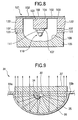
- FIG. 9 is a sectional view showing an example of the reflective LED.
- the reflective LED 31 is configured so that a light-emitting element 32 is mounted on a forward end of one 33b of a pair of leads 33a and 33b through which electric power is supplied to the light-emitting element 32.
- the light-emitting element 32 and the other lead 33a are bonded and electrically connected to each other by a wire 34.
- the light-emitting element 32, the pair of leads 33a and 33b and the wire 34 are sealed with a transparent epoxy resin 35.
- the transparent epoxy resin 35 forms a reflecting surface shaped like a paraboloid of revolution with the light-emitting element 32 as its focal point so that the reflecting surface is disposed opposite to the light-emitting element 32.
- Aluminum vapor deposition is applied onto an outside of the reflecting surface so that a concave reflecting mirror 36 is formed on the outside of the reflecting surface.
- the reflective LED 31 is configured so that light emitted from the light-emitting element 32 can be radiated out as light condensed with high efficiency.
- the area of the reflecting surface of the reflective LED 31 viewed from the outside is, however, so large that dark noise (pseudo-lighting) due to reflection of external light occurs largely when the reflective LED 31 is turned off. As a result, there arises a problem that contrast between light when the reflective LED 31 is turned on and light when the reflective LED 31 is turned off is low.
- an object of the invention is to provide a shielded reflective light-emitting diode which can be mounted on a surface and in which characteristics of luminous intensity distributions of light-emitting elements can be made uniform as well as display unevenness of a display can be reduced.
- Another object of the invention is to provide a shielded reflective device which is high in external radiation efficiency, high in contrast between light when the device is turned on and light when the device is turned off, and excellent in heat-radiating characteristic; and to provide a light source used for the shielded reflective device.
- the light source portion is mounted on the heat-dissipation conductive member of the. substrate portion.
- the heat-dissipation conductive member reaches the rear surface of the substrate portion. Hence, heat generated from the light source portion is transmitted to the rear surface of the substrate portion through the heat-dissipation conductive member. Hence, heat generated from the light source portion can be radiated well.
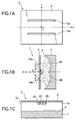
- Fig. 1A is a plan view showing the configuration of a shielded reflective light-emitting diode according to Embodiment 1 of the invention.
- Fig. 1B is a longitudinal sectional view taken along the Y direction in Fig. 1A.
- Fig. 1C is a longitudinal sectional view taken along the X direction in Fig. 1A.
- Fig. 2A is a plan view showing the configuration of a light source used in the shielded reflective light-emitting diode according to Embodiment 1 of the invention.
- Fig. 2B is a longitudinal sectional view taken along the Y direction.
- Fig. 2C is a longitudinal sectional view taken along the X direction.
- a light-shielding member 9 which serves also as a mount substrate. LED light is radiated out through these optical opening portions 10a and 10b.
- a light source 2 having a light-emitting element is mounted on a rear surface of the light-shielding member 9 and between the optical opening portions 10a and 10b.
- the light source 2 is so small-sized that only one light-emitting element is sealed with a resin.
- the light source 2 can be surface-mounted with a very low defective rate and substantially without being influenced by heat distortion based on the difference in thermal expansion coefficient between resin and metal even at a high temperature near 200°C required for surface mounting.
- a reflecting substrate 7 is disposed in a position opposite to the light source 2 and far from the light-shielding member 9.
- the reflecting substrate 7 has a concave surface of a polycarbonate resin, and a reflecting mirror 8 formed on the concave surface by aluminum vapor deposition.
- a reflecting surface 8a of the reflecting mirror 8 is formed as a cylindrical surface in which a part of an ellipse with the light source 2 and the optical opening portion 10a as its two focal points is extended in the lengthwise direction of the optical opening portion 10a (X direction in Fig. 1A).
- a reflecting surface 8b of the reflecting mirror 8 is formed as a cylindrical surface in which a part of an ellipse with the light source 2 and the optical opening portion 10b as its two focal points is extended in the lengthwise direction of the optical opening portion 10b.
- all light emitted from the light source 2 and reflected by the reflecting surface 8a is condensed into the optical opening portion 10a and then radiated out through the optical opening portion 10a.
- all light emitted from the light source 2 and reflected by the reflecting surface 8b is condensed into the optical opening portion 10b and then radiated out through the optical opening portion 10b.
- the shielded reflective LED 1 As shown in Fig. 1C, in the shielded reflective LED 1 according to Embodiment 1, three light sources 2R, 2G and 2B are mounted on the rear surface of the light-shielding member 9 so as to be arranged side by side in the X direction. That is, a red light source 2R, a green light source 2G and a blue light source 2B for emitting light in three primary colors respectively are mounted densely in the X-direction center. Hence, when electric power supplied to each of the light sources 2R, 2G and 2B is controlled, light in any color can be radiated from the shielded reflective LED 1. That is, the shielded reflective LED 1 can be applied to a full color display.
- each of the three-color light sources 2R, 2G and 2B a light-emitting element is sealed with a resin.
- variations in luminous intensity and chromaticity of light-emitting elements used for each of the three-color light sources 2R, 2G and 2B can be easily examined and selected before mounting.
- the reflecting mirror 8 has cylindrical surfaces in which a part of an ellipse with the light source 2 and the optical opening portion 10a or 10b as its two focal points is extended in the lengthwise direction of the optical opening portion 10a or 10b, there is no axial displacement when such a plurality of light sources 2R, 2G and 2B are arranged along the lengthwise direction.
- the light source 2 has a light-emitting element 3, a pair of leads 4a and 4b through which electric power is supplied to the light-emitting element 3, and a concave reflecting mirror 4c formed at a forward end of one 4a of the leads.
- the light-emitting element 3 is mounted on a bottom surface of the reflecting mirror 4c by silver paste.
- the light-emitting element 3 After the light-emitting element 3 is bonded and electrically connected to the other lead 4b by a wire 5, the light-emitting element 3, the reflecting mirror 4c, the wire 5 and part of the pair of leads 4a and 4b are sealed with a transparent epoxy resin 6 which serves as a light-transmissive material. At the same time, a light-radiating surface 6a is formed on the light-emitting surface side of the light-emitting element 3. Then, portions of the leads 4a and 4b protruded from the transparent epoxy resin 6 are bent substantially perpendicularly along the side surfaces of the transparent epoxy resin 6 and further bent substantially perpendicularly along the rear surface of the transparent epoxy resin 6. Thus, the light source 2 is provided as a light source which can be surface-mounted.
- the concave reflecting mirror 4c is provided around the light-emitting element 3. Hence, light emitted horizontally from the light-emitting surface of the light-emitting element 3 is also reflected by the concave reflecting mirror 4c, so that light can be radiated from the light-emitting element 3 while concentrated into an angle range of about 70 degrees with respect to the axis perpendicular to the light-emitting surface of the light-emitting element 3. Hence, the necessity that an end surface of the reflecting mirror 8 must reach a position tangent to the light-shielding member 9 as shown in Fig. 1B is eliminated.
- the reflecting mirror 8 can be disposed so as to be far from the light source 2 and from the light-shielding member 9.
- Light applied to opposite end surfaces 7a of the cylindrical reflecting mirror 8 shown in Fig. 1C may be absorbed without being reflected.
- the range of light applied to the concave reflecting mirror 4c is narrowed to an angle range of about 70 degrees with respect to the axis perpendicular to the light-emitting surface.
- light can be prevented from being applied to the opposite end surfaces 7a. That is, light emitted from the light-emitting element 3 can be prevented from being consumed wastefully.
- reflecting mirrors may be disposed on the opposite end surfaces 7a perpendicular to the cylindrical surface.
- the light-radiating surface 6a of the light source 2 is shaped so that a top portion of an ellipsoidal convex lens is cut in the direction of the major diameter of the ellipsoid by a curved cylindrical surface.
- the Y-direction component of light emitted from the light-emitting element 3 and radiated from the light-radiating surface 6a is refracted obliquely.
- a portion of the reflecting mirror 8 just under the light source 2 is little irradiated with light. That is, light radiated out through the slit-like optical opening portions 10a and 10b has a large amount of Z-direction component.
- the spreading angle of light in the vertical direction (Y direction) is narrowed so that light-radiating characteristic favorable to the display can be obtained.
- the X-direction component of light is spread and reflected by the reflecting mirror 8 because light emitted from the light-emitting element 3 is radiated from the light-radiating surface 6awhich is an elliptic surface.
- the reflected light is radiated all over the slit length of the optical opening portions 10a and 10b.
- the spreading angle of light in the horizontal direction (X direction) is widened so that light-radiating characteristic favorable to the display can be obtained.
- the LED can be provided as a shielded reflective LED which is high in contrast between light at the time of turning-on and light at the time of turning-off.
- Fig. 3A is a plan view showing the configuration of a shielded reflective light-emitting diode according to Embodiment 2 of the invention.
- Fig. 3B is a longitudinal sectional view taken along the Y direction in Fig. 3A.
- Fig. 3C is a longitudinal sectional view taken along the X direction in Fig. 3A.
- a light-shielding member 19 which serves also as a mount substrate. LED light is radiated out through these optical opening portions 20a, 20b, 20c and 20d.
- a light source 2 having a light-emitting element is mounted on a rear surface of the light-shielding member 19 and between the optical opening portions 20b and 20c.
- the configuration of the light source 2 is the same as that in Embodiment 1.
- the light source 2 is so small-sized that only one light-emitting element 3 is sealed with a transparent epoxy resin 6.
- the light source 2 can be surface-mounted with a very low defective rate.and substantially without being influenced by heat distortion based on the difference in thermal expansion coefficient between resin and metal even at a high temperature near 200°C required for surface mounting.
- a reflecting substrate 17 is disposed in a position opposite to the light source 2 and far from the light-shielding member 19.
- the reflecting substrate 17 has a concave surface of a polycarbonate resin, and a reflecting mirror 18 formed on the concave surface by aluminum vapor deposition.
- a reflecting surface 18a of the reflecting mirror 18 is formed as a cylindrical surface in which a part of an ellipse with the light source 2 and the optical opening portion 20a as its two focal points is extended in the lengthwise direction of the optical opening portion 20a (X direction in Fig. 3A).
- a reflecting surface 18b of the reflecting mirror 18 is formed as a cylindrical surface in which a part of an ellipse with the light source 2 and the optical opening portion 20b as its two focal points is extended in the lengthwise direction of the optical opening portion 20b.
- a reflecting surface 18c of the reflecting mirror 18 is formed as a cylindrical surface in which a part of an ellipse with the light source 2 and the optical opening portion 20c as its two focal points is extended in the lengthwise direction of the optical opening portion 20c.
- a reflecting surface 18d of the reflectingmirror 18 is formed as a cylindrical surface in which a part of an ellipse with the light source 2 and the optical opening portion 20d as its two focal points is extended in the lengthwise direction of the optical opening portion 20d.
- all light emitted from the light source 2 and reflected by the reflecting surface 18a is condensed into the optical opening portion 20a and then radiated out through the optical opening portion 20a.
- all light emitted from the light source 2 and reflected by the reflecting surface 18b is condensed into the optical opening portion 20b and then radiated out through the optical opening portion 20b.
- all light emitted from the light source 2 and reflected by the reflecting surface 18c is condensed into the optical opening portion 20c and then radiated out through the optical opening portion 20c.
- all light emitted from the light source 2 and reflected by the reflecting surface 18d is condensed into the optical opening portion 20d and then radiated out through the optical opening portion 20d.
- the light-radiating surface 6a of the light source 2 in this embodiment is shaped so that a top portion of an ellipsoidal convex lens is cut in the direction of the major diameter of the ellipsoid by a curved cylindrical surface.
- the Y-direction component of light emitted from the light-emitting element 3 and radiated from the light-radiating surface 6a is refracted obliquely.
- a portion of the reflecting mirror 18 just under the light source 2 is little irradiated with light.
- the X-direction component of light is spread and reflected by the reflecting mirror 18 because light emitted from the light-emitting element 3 is radiated from the light-radiating surface 6a which is an elliptic surface, as described above for Embodiment 1.
- the reflected light is radiated all over the slit length of the optical opening portions 20a, 20b, 20c and 20d.
- the LED can be provided as a shielded reflective LED which is high in contrast between light at the time of turning-on and light at the time of turning-off.
- the shielded reflective LED 11 As shown in Fig. 3C, in the shielded reflective LED 11 according to Embodiment 2, three light sources 2R, 2G and 2B are mounted on the rear surface of the light-shielding member 19 so as to be arranged side by side in the X direction in the same manner as in Embodiment 1. That is, a red light source 2R, a green light source 2G and a blue light source 2B for emitting light in three primary colors respectively are mounted densely in the X-direction center. Hence, when electric power supplied to each of the light sources 2R, 2G and 2B is controlled, light in any color can be radiated from the shielded reflective LED 11. That is, the shielded reflective LED 11 can be applied to a full color display.
- each of the three-color light sources 2R, 2G and 2B a light-emitting element is sealed with a resin.
- variations in luminous intensity and chromaticity of light-emitting elements used for each of the three-color light sources 2R, 2G and 2B can be easily examined and selected before mounting.
- the reflecting mirror 18 has cylindrical surfaces in which a part of an ellipse with the light source 2 and each of the optical opening portions 20a, 20b, 20c and 20d as its two focal points is extended in the lengthwise direction of the optical opening portion, there is no axial displacement when such a plurality of light sources 2R, 2G and 2B are arranged along the lengthwise direction.
- Light applied to opposite end surfaces 17a of the cylindrical reflectingmirror 18 shown in Fig. 3C may be absorbed without being reflected.
- the range of light applied to the concave reflecting mirror 4c is narrowed to an angle range of about 70 degrees with respect to the axis perpendicular to the light-emitting surface.
- light can be prevented from being applied to the opposite end surfaces 17a. That is, light emitted from the light-emitting element 3 can be prevented from being consumed wastefully.
- reflecting mirrors may be disposed on the opposite end surfaces 17a perpendicular to the cylindrical surface.
- the respective embodiments have been described upon the case where the light-emitting element 3, the concave reflecting mirror 4C, etc. in the light source 2 are sealed with the transparent epoxy resin 6 which serves as a light-transmissive material, the invention may be applied also to the case where they are not sealed with such a resin.
- the respective embodiments have been described upon the case where the light-radiating surface 6a formed by the transparent epoxy resin 6 is shaped so that a top portion of an ellipsoidal convex lens is cut in the direction of the major diameter of the ellipsoid by a curved cylindrical surface, the invention maybe applied also to the case where the light-radiating surface is shaped variously, such as like a flat surface, a semi-spherical surface with the light-emitting element as its origin, or an elliptic surface.
- any light-transmissive material such as a transparent silicone resin may be used if conditions such as fluidity and filling characteristic before curing and transparency and strength after curing can be satisfied.
- each of the optical opening portions 10a, 10b, 20a, 20b, 20c and 20d is shaped like a slit
- the optical opening portion need not be shaped like a slit, that is, any shape may be used if the shape is formed so that light condensed by the reflecting mirror can be transmitted through the optical opening portion.
- each of the optical opening portions 10a, 10b, 20a, 20b, 20c and 20d is formed as a through-hole
- the invention may be applied also to the case where the optical opening portion is formed as a hole filled with a light-transmissive material such as transparent epoxy resin or glass.
- a light-transmissive material such as transparent epoxy resin or glass.
- the respective embodiments have been described upon the case where two or four slit-like optical opening portions are provided, the number of slit-like opening portions is not limited thereto, that is, one slit-like opening portion may be provided or three slit-like opening portions may be provided.
- a mount substrate for surface-mounting the light source 2 is provided with slit-like optical opening portions and serves as a light-shielding member
- the invention may be applied also to the case where a light-shielding member is provided separately from a mount substrate in the condition that holes larger than the optical opening portions are formed in the mount substrate.
- the red light source 2R, the green light source 2G and the blue light source 2B for emitting light in three primary colors respectively are mounted as light sources 2
- the colors of light emitted from the light sources are not limited to these three colors and the light sources need not emit light in such a plurality of colors.
- the number of light sources is not limited, that is, one light source maybe provided.
- the other configuration of the shielded reflective light-emitting diode as to the shape, the number of parts, the material, the size and the connecting relation thereof is not limited to the embodiments.
- Fig. 4 is a front view showing the periphery of an optical opening portion in the shielded reflective device according to Embodiment 3 of the invention.
- Fig. 4 is a longitudinal sectional view showing the shielded reflective device according to Embodiment 3 of the invention.
- Fig. 5 is a plan view showing the overall configuration of the light source according to Embodiment 3 of the invention.
- Fig. 7 is a longitudinal sectional view showing the overall configuration of the light source according to Embodiment 1 of the invention.
- a shielded reflective LED 1 which is the shielded reflective device according to Embodiment 3 of the invention has an optical opening portion 102 which is substantially circularly shaped and very narrow. Even in the case where the optical opening portion 102 is narrow as described above, high external radiation efficiency can be obtained. This is because the optical opening portion 102 is provided in a 0.1 mm-thick black PET film (douser) 103.
- the black PET film 103 has front and rear surfaces which are sandblasted so as to be matted.
- the light source 110 of the shielded reflective LED 101 is a lens type LED having a light-emitting element sealed with a transparent epoxy resin.
- a concave reflecting surface which is formed so that a part of an ellipsoid with the light source 110 and the optical opening portion 102 as its two focal points is rotated around the center axis of the light source 110, is formed on a reflecting substrate 105 which is injection-molded of an acrylic resin.
- Aluminum vapor deposition is applied onto the reflecting surface to thereby form a reflecting mirror 106. Hence, all light emitted from the light source 110 and reflected by the reflecting mirror 106 is radiated out through the optical opening portion 102.
- the condensed light has a certain degree of width in the vicinity of the focal point.
- the douser (light-shielding member) 103 is a thick plate, external radiation efficiency cannot be made high if the width of the optical opening portion 102 is not large.
- high external radiation efficiency can be obtained even in the case where the width of the optical opening portion 102 is narrow, because the douser 103 is a 0.1 mm-thick film.
- the douser 103 is stuck onto a 0.6 mm-thick transparent glass plate 104.
- a substrate portion 107 made of a double-side through-hole glass epoxy substrate is fixed to a rear surface of the transparent glass plate 104.
- the light source 110 is mounted on a lower surface of the substrate portion 107 through a substrate 111 of a light source portion.
- the substrate 111 of the light source portion is made of a glass epoxy double-side through-hole substrate having four corners which are cut so that the cut four corners correspond to through-holes respectively. That is, because the substrate 111 is shaped so that its four corners are cut, light reflected by the reflecting mirror 106 can be prevented from being blocked.
- a through-hole is also formed in the center portion of the substrate 111 on which the light-emitting element 112 will be mounted.
- a hollow portion of the through-hole is filled with metal powder 116 and the through-hole is plated with the metal powder 116.
- the recognition rate is lowered.
- the through-hole is filled with metal powder 116 and plated with the metal powder 16, sufficient flatness can be obtained so that there is no influence on the operating efficiency of auto wire-bonding.
- the light-emitting element 112 is mounted on the plating and electrically connected by a wire 104 in the manner of auto wire-bonding.
- a lens 115a shaped like a semi-sphere with the light-emitting element 112 as its origin is formed of a transparent epoxy resin 115.
- this semispherical lens 115a light emitted from the light-emitting element 112 is made perpendicularly incident on the transparent epoxy resin 115 and then radiated out without being refracted. Hence, the apparent light-emitting area of the light source portion can be minimized.
- the light source portion 110 and the substrate 111 produced in this manner are further placed on the substrate portion 107.
- the substrate portion 107 is made of a double-side through-hole substrate which is thicker than the substrate 11 and which is cut into a substantially cylindrical shape.
- the portion extended upward in Fig. 6 is equivalent to a connecting portion 103a of the douser 103.
- the through-hole of the substrate portion 107 is located just under the portion filled with the metal powder 116, of the substrate 111.
- the through-hole is filled with solder 117 so that the left side of the substrate 111 and the left side of the substrate portion 107 are electrically connected to each other by the solder 17 and the right side of the substrate 111 and the right side of the substrate portion 107 are electrically connected to each other by the solder 117 while the left side and the right side as a whole are kept electrically insulated from each other.
- the through-hole just under the light-emitting element 112 is filled with metal powder 116 and the through-hole just under the first-mentioned through-hole is further filled with solder 117.
- heat generated from the light-emitting element 112 is transmitted through the metal powder 116 and the solder 117 and radiated out.
- the light source 110 is provided as a light source excellent in heat-radiating characteristic.
- the surface 107a and cylindrical circumference of the substrate portion 107 are silk-screen-printed in black.
- external light which enters the inside of the shielded reflective LED 1 through the optical opening portion 102 shown in Figs. 4 and 5 is reflected by the reflecting mirror 106.
- the reflected light strikes the surface 107a of the substrate portion 107 so as to be absorbed thereto.
- pseudo-lighting in which external light reflected by the reflecting mirror 106 is radiated out again through the optical opening port ion 102 when the device is turned off can be prevented thoroughly.
- the LED 101 can be provided as a shielded reflective LED which is high in contrast between light when the device is turned on and light when the device is turned off.
- a shielded reflective LED 1 which is high in external radiation efficiency, high in contrast between light when the device is turned on and light when the device is turned off, and excellent in heat-radiating characteristic; and there can be also provided a light source 110 for the. shielded reflective LED 101.
- FIG. 8 is a longitudinal sectional view showing the shielded reflective device according to Embodiment 4 of the invention.
- the point of difference of the shielded reflective LED 121 according to Embodiment 4 from the shielded reflective LED 101 according to Embodiment 3 is in that a first spacer 122 and a second spacer 123 are put between the glass plate 104 and the through-hole substrate (substrate portion) 107 and between the through-hole substrate 107 and the reflecting substrate 105 respectively.
- the focal length from the light source 110 to the optical opening portion 102 can be made so large that characteristic of luminous intensity distribution with high degree of light condensation can be obtained.
- the surface of the substrate portion 107, the surface of the first spacer 122 and the surface of the second spacer 123 are silk-screen-printed in black.
- external light which enters the inside of the shielded reflective LED 121 through the optical opening portion 102 is reflected by the reflecting mirror 106.
- the reflected light strikes the surfaces of the substrate portion 107 and the first and second spacers 122 and 123 so as to be absorbed thereto.
- pseudo-lighting in which external light reflected by the reflecting mirror 106 is radiated out again through the optical opening portion 102 when the device is turned off can be prevented thoroughly.
- the shielded reflective LED 121 can be provided as a shielded reflective LED which is high in contrast between light when the device is turned on and light when the device is turned off.
- a shielded reflective LED 121 which is high in external radiation efficiency, high in contrast between light when the device is turned on and light when the device is turned off, and high in degree of light condensation.
- the light source portion is not limited to such an LED.
- the invention may be applied also to a shielded reflective device using any other light source such as an EL or the like as a light source.
- the LED light-emitting element is suitable for the shielded reflective device because the light-emitting area of the LED light-emitting element is so small that the width of light condensation at the light-condensing portion can be narrowed.
- the embodiments have been described upon the case where the whole surface of the substrate portion 107 is silk-screen-printed in black, the invention may be applied also to the case where only the surface 107a of the substrate portion 107 on which the light source portion 110 and the substrate 111 are mounted is printed in black.
- the substrate portion is made of a glass epoxy substrate
- the invention may be applied also to the case where the substrate portion is made of any other material such as a ceramic substrate or made of a material like a metal stem.
- a transparent epoxy resin 115 is used as a light-transmissive material
- the invention is not limited thereto.
- any other material such as a transparent silicone resin may be used as the light-transmissive material.
- the other portions of the shielded reflective device and the light source as to the configuration, shape, number of parts, material, size and connection relation thereof are not limited to the embodiments.
- the black substrate portion, space or heat-dissipation conductive member in the Embodiments 3 and 4 can be incorporated into the shielded reflective light-emitting diode according to the Embodiments 1 and 2.
Landscapes
- Led Device Packages (AREA)
Abstract

Description
Claims (20)
- A shielded reflective light-emitting diode comprising:wherein said light-shielding member has an optical opening portion, andat least one light source including at least one light-emitting element;a reflecting mirror provided opposite to said light source; anda light-shielding member for limiting external light incident on said reflecting mirror,
said reflecting mirror is shaped like a cylindrical surface in which light emitted from said light source and reflected by said reflecting mirror is condensed linearly so that the linearly condensed light is radiated out through said optical opening portion of said light-shielding member. - A shielded reflective light-emitting diode according to claim 1, wherein said optical opening portion has a size and a shape equivalent to those of an area of light condensed by said reflecting mirror shaped like a cylindrical surface.
- A shielded reflective light-emitting diode according to claim 1, wherein said light source further includes a concave reflecting mirror provided around said light-emitting element.
- A shielded reflective light-emitting diode according to claim 3, wherein said light source further includes a light-transmissive material with which said light-emitting element and said concave reflecting mirror are sealed and which forms a light-radiating surface on a light-emitting surface side of said light-emitting element.
- A shielded reflective light-emitting diode according to claim 4, wherein said light-radiating surface is constituted by a convex lens.
- A shielded reflective light-emitting diode according to claim 4, wherein said light-radiating surface is a curved cylindrical surface shaped so that a top portion of an ellipsoidal convex lens with a major diameter direction facing toward a direction substantially perpendicular to a lengthwise direction of said reflecting mirror shaped like a cylindrical surface is cut in said major diameter direction.
- A shielded reflective light-emitting diode according to claim 1, wherein a plurality of light sources which are arranged along an axial direction of said reflecting mirror shaped like a cylindrical surface are used as said at least one light source.
- A shielded reflective light-emitting diode according to claim 1, wherein a plurality of light sources which emit light in different colors respectively are used as said at least one light source.
- A shielded reflective light-emitting diode according to claim 8, wherein a red light source having a red light-emitting element, a green light source having a green light-emitting element and a blue light source having a blue light-emitting element are used as said at least one light source.
- A shielded reflective light-emitting diode according to claim 1, further comprising a substrate portion for mounting said light source on said light-shielding member, and a side of said substrate portion on which said light source is mounted is black.
- A shielded reflective light-emitting diode according to claim 10, further comprising a spacer which is provided for changing a height of said substrate portion and which is black.
- A shielded reflective light-emitting diode according to claim 1, wherein said light-shielding member is shaped like a film.
- A shielded reflective device comprising:wherein said shielded reflective device further comprises a substrate portion on which said light source portion is mounted, anda light source portion including a light-emitting portion;a reflecting mirror provided opposite to a light-radiating side of said light source portion; anda douser including an optical opening portion,
a side of said substrate portion on which said light source portion is mounted is black. - A shielded reflective device according to claim 13, further comprising a spacer which is provided for changing a height of said substrate portion and which is black.
- A shielded reflective device comprising:wherein said douser is shaped like a film.a light source portion including a light-emitting portion;a reflecting mirror provided opposite to a light-radiating side of said light source portion; anda douser including an optical opening portion,
- A light source comprising:wherein a portion of said substrate on which said light-emitting element is mounted is made of a heat-dissipation conductive member, anda light-emitting element;a light-transmissive material with which said light-emitting element is sealed; anda substrate,
said heat-dissipation conductive member reaches a rear surface of said substrate. - A light source according to claim 16, wherein said light-transmissive material forms a convex lens.
- A light source according to claim 16, wherein said substrate is shaped so that four corners of said substrate are cut.
- A light source according to claim 17, wherein (width of said substrate - diameter of said convex lens) ≤ 1 mm is satisfied.
- A shielded reflective device comprising:wherein a portion of said substrate on which said light-emitting element is mounted is made of a heat-dissipation conductive member, anda light-emitting element;a light-transmissive material with which said light-emitting element is sealed; anda substrate,a reflecting mirror provided opposite to a light-radiating side of said light-emitting element; anda douser including an optical opening portion,
said heat-dissipation conductive member reaches a rear surface of said substrate,
said light-transmissive material forms a convex lens, and
(width of said substrate - diameter of said convex lens) ≤ 1 mm is satisfied.
Applications Claiming Priority (4)
| Application Number | Priority Date | Filing Date | Title |
|---|---|---|---|
| JP2001194590A JP3722018B2 (en) | 2001-06-27 | 2001-06-27 | Light-shielding reflective light-emitting diode |
| JP2001194590 | 2001-06-27 | ||
| JP2001308256A JP2003115204A (en) | 2001-10-04 | 2001-10-04 | Light-shielding reflective device and light source |
| JP2001308256 | 2001-10-04 |
Publications (2)
| Publication Number | Publication Date |
|---|---|
| EP1276157A2 true EP1276157A2 (en) | 2003-01-15 |
| EP1276157A3 EP1276157A3 (en) | 2005-02-09 |
Family
ID=26617646
Family Applications (1)
| Application Number | Title | Priority Date | Filing Date |
|---|---|---|---|
| EP02014003A Withdrawn EP1276157A3 (en) | 2001-06-27 | 2002-06-26 | Shielded reflective light-emitting device |
Country Status (2)
| Country | Link |
|---|---|
| US (1) | US6886962B2 (en) |
| EP (1) | EP1276157A3 (en) |
Cited By (7)
| Publication number | Priority date | Publication date | Assignee | Title |
|---|---|---|---|---|
| WO2008040297A1 (en) * | 2006-10-04 | 2008-04-10 | Osram Opto Semiconductors Gmbh | Optical element for a light-emitting diode, light-emitting diode, led arrangement and method for producing an led arrangement |
| WO2008047851A1 (en) * | 2006-10-12 | 2008-04-24 | Panasonic Corporation | Light-emitting apparatus |
| EP1981147A1 (en) * | 2007-04-11 | 2008-10-15 | FELA Hitzinger GmbH | Illumination unit with transparent substrate and substrate-mounted LED |
| WO2009004511A1 (en) * | 2007-06-06 | 2009-01-08 | Koninklijke Philips Electronics N.V. | Thin luminaire for general lighting applications |
| WO2012034909A1 (en) * | 2010-09-15 | 2012-03-22 | Osram Opto Semiconductors Gmbh | Light fixture |
| EP2484553A3 (en) * | 2011-02-07 | 2012-12-05 | Koito Manufacturing Co., Ltd. | Vehicle lamp and optical unit thereof |
| CH710609A1 (en) * | 2015-01-14 | 2016-07-15 | Regent Beleuchtungskörper Ag | Lamp with primary and secondary radiation direction. |
Families Citing this family (38)
| Publication number | Priority date | Publication date | Assignee | Title |
|---|---|---|---|---|
| US6833566B2 (en) * | 2001-03-28 | 2004-12-21 | Toyoda Gosei Co., Ltd. | Light emitting diode with heat sink |
| US6896381B2 (en) | 2002-10-11 | 2005-05-24 | Light Prescriptions Innovators, Llc | Compact folded-optics illumination lens |
| US7377671B2 (en) * | 2003-02-04 | 2008-05-27 | Light Prescriptions Innovators, Llc | Etendue-squeezing illumination optics |
| US8075147B2 (en) * | 2003-05-13 | 2011-12-13 | Light Prescriptions Innovators, Llc | Optical device for LED-based lamp |
| US7329029B2 (en) | 2003-05-13 | 2008-02-12 | Light Prescriptions Innovators, Llc | Optical device for LED-based lamp |
| EP1664851B1 (en) | 2003-07-28 | 2014-11-12 | Light Prescriptions Innovators, LLC. | Three-dimensional simultaneous multiple-surface method and free-form illumination-optics designed therefrom |
| US7144121B2 (en) * | 2003-11-14 | 2006-12-05 | Light Prescriptions Innovators, Llc | Dichroic beam combiner utilizing blue LED with green phosphor |
| US7695159B2 (en) * | 2004-11-26 | 2010-04-13 | Garry Ian Holloway | Apparatus and method for illuminating articles of jewelry |
| WO2006066459A1 (en) * | 2004-12-23 | 2006-06-29 | Beijing Yuande Bio-Medical Engineering Co., Ltd. | A standard light source for a single photon counter |
| CN100494991C (en) * | 2004-12-23 | 2009-06-03 | 北京源德生物医学工程有限公司 | Standard light source for single photon counting instrument |
| US8393777B2 (en) * | 2005-07-28 | 2013-03-12 | Light Prescriptions Innovators, Llc | Etendue-conserving illumination-optics for backlights and frontlights |
| EP1920285A4 (en) * | 2005-07-28 | 2010-11-03 | Light Prescriptions Innovators | OPEN-FREE LENTICULAR OPTICAL ELEMENTS AND THEIR APPLICATION TO CAPACITORS AND PROJECTORS |
| US8631787B2 (en) * | 2005-07-28 | 2014-01-21 | Light Prescriptions Innovators, Llc | Multi-junction solar cells with a homogenizer system and coupled non-imaging light concentrator |
| WO2008008994A2 (en) * | 2006-07-14 | 2008-01-17 | Light Prescriptions Innovators, Llc | Brightness-enhancing film |
| WO2008022064A2 (en) * | 2006-08-10 | 2008-02-21 | Light Prescriptions Innovators, Llc | Led light recycling device |
| WO2008022065A2 (en) * | 2006-08-11 | 2008-02-21 | Light Prescriptions Innovators, Llc | Led luminance-enhancement and color-mixing by rotationally multiplexed beam-combining |
| US20080080170A1 (en) * | 2006-10-03 | 2008-04-03 | Vernon Lombard | Integrated Lighting System for Helmets |
| JP5326204B2 (en) | 2006-11-29 | 2013-10-30 | 富士通株式会社 | LIGHT EMITTING COMPONENT, ITS MANUFACTURING METHOD, LIGHT EMITTING COMPONENT ASSEMBLY AND ELECTRONIC DEVICE |
| CN101275720B (en) * | 2007-03-28 | 2010-12-01 | 鸿富锦精密工业(深圳)有限公司 | LED lighting device |
| JP5060172B2 (en) * | 2007-05-29 | 2012-10-31 | 岩谷産業株式会社 | Semiconductor light emitting device |
| US7513634B2 (en) * | 2007-05-21 | 2009-04-07 | National Tsing Hua University | Structure of planar illuminator |
| DE102008048846B4 (en) * | 2008-09-25 | 2024-11-28 | OSRAM Opto Semiconductors Gesellschaft mit beschränkter Haftung | optoelectronic component |
| US20110051413A1 (en) | 2009-08-25 | 2011-03-03 | Abl Ip Holding Llc | Optic shielding |
| FI123457B (en) * | 2009-09-24 | 2013-05-15 | Oversol Oy | Reflector and this utilizing lighting device |
| DE102010002884B4 (en) * | 2010-03-15 | 2014-05-28 | Irlbacher Blickpunkt Glas Gmbh | Lighting unit, its use as a display and method of making the lighting unit |
| CN103137823B (en) * | 2011-11-24 | 2015-10-07 | 展晶科技(深圳)有限公司 | Light-emitting diode and apply the direct-light-type backlight of this light-emitting diode |
| CN103017085B (en) * | 2012-12-14 | 2015-08-05 | 京东方科技集团股份有限公司 | Mirror lens, the backlight module using this mirror lens and display device |
| US9220394B2 (en) | 2013-08-15 | 2015-12-29 | Whirlpool Corporation | LED console assembly with light reflector |
| US9933131B2 (en) | 2013-10-29 | 2018-04-03 | Whirlpool Corporation | Integrated console display assembly |
| US9982866B2 (en) | 2013-10-29 | 2018-05-29 | Whirlpool Corporation | Console assembly with integrated light reflector cups |
| US20150113841A1 (en) * | 2013-10-29 | 2015-04-30 | Whirlpool Corporation | Alphanumeric display assembly |
| EP3168160B1 (en) | 2015-11-13 | 2018-07-11 | Goodrich Lighting Systems GmbH | Exterior aircraft light unit and aircraft comprising the same |
| US10393348B2 (en) * | 2017-02-24 | 2019-08-27 | Glint Photonics, Inc. | Configurable luminaire |
| CN107611243B (en) * | 2017-09-26 | 2024-03-26 | 利亚德光电股份有限公司 | Display unit and display device |
| CN112526786B (en) * | 2020-11-27 | 2022-09-27 | 北海惠科光电技术有限公司 | Color film substrate, display panel and display device |
| CN112631026B (en) * | 2020-12-31 | 2024-05-10 | 联晶智能电子有限公司 | Backlight lens and module |
| CN114859598A (en) | 2022-04-22 | 2022-08-05 | Tcl华星光电技术有限公司 | Light-emitting plate and preparation method thereof |
| WO2026052387A1 (en) * | 2024-09-06 | 2026-03-12 | Signify Holding B.V. | Linear luminaire |
Family Cites Families (17)
| Publication number | Priority date | Publication date | Assignee | Title |
|---|---|---|---|---|
| DE2315709A1 (en) * | 1973-03-29 | 1974-10-10 | Licentia Gmbh | RADIATION-EMISSING SEMI-CONDUCTOR ARRANGEMENT WITH HIGH RADIATION POWER |
| US4816694A (en) * | 1985-08-15 | 1989-03-28 | Sanders Associates, Inc. | Radiation system |
| EP0450560B1 (en) * | 1990-04-03 | 1998-07-22 | Sumitomo Electric Industries, Ltd. | An optical device |
| US5167556A (en) * | 1990-07-03 | 1992-12-01 | Siemens Aktiengesellschaft | Method for manufacturing a light emitting diode display means |
| US5506755A (en) * | 1992-03-11 | 1996-04-09 | Kabushiki Kaisha Toshiba | Multi-layer substrate |
| JP3109960B2 (en) * | 1994-07-18 | 2000-11-20 | キヤノン株式会社 | Recording medium and image forming method using the same |
| US5921666A (en) * | 1997-03-04 | 1999-07-13 | Thomas Lighting | Ellipsoidal slot light |
| GB2324598B (en) | 1997-04-21 | 2001-04-18 | Microsense Systems Ltd | A display |
| US6335548B1 (en) * | 1999-03-15 | 2002-01-01 | Gentex Corporation | Semiconductor radiation emitter package |
| JP2000223751A (en) * | 1998-11-25 | 2000-08-11 | Nichia Chem Ind Ltd | Led lamp and display device using the led lamp |
| JP3447604B2 (en) * | 1999-02-25 | 2003-09-16 | 株式会社シチズン電子 | Surface mount type light emitting diode and method of manufacturing the same |
| JP2000299502A (en) | 1999-04-13 | 2000-10-24 | Seiwa Electric Mfg Co Ltd | LED lamp |
| JP3833019B2 (en) * | 1999-08-31 | 2006-10-11 | 日亜化学工業株式会社 | Light emitting diode |
| CN1311566C (en) | 1999-11-30 | 2007-04-18 | 欧姆龙株式会社 | Optical device and apparatus comprising said optical device |
| US6729746B2 (en) * | 2000-03-14 | 2004-05-04 | Toyoda Gosei Co., Ltd. | Light source device |
| US20020085390A1 (en) * | 2000-07-14 | 2002-07-04 | Hironobu Kiyomoto | Optical device and apparatus employing the same |
| JP3753011B2 (en) | 2001-04-11 | 2006-03-08 | 豊田合成株式会社 | Reflective light emitting diode |
-
2002
- 2002-06-26 US US10/179,377 patent/US6886962B2/en not_active Expired - Fee Related
- 2002-06-26 EP EP02014003A patent/EP1276157A3/en not_active Withdrawn
Cited By (13)
| Publication number | Priority date | Publication date | Assignee | Title |
|---|---|---|---|---|
| CN101536186B (en) * | 2006-10-04 | 2012-07-18 | 奥斯兰姆奥普托半导体有限责任公司 | Optical element for light emitting diode, light emitting diode, LED device and method for manufacturing LED device |
| WO2008040297A1 (en) * | 2006-10-04 | 2008-04-10 | Osram Opto Semiconductors Gmbh | Optical element for a light-emitting diode, light-emitting diode, led arrangement and method for producing an led arrangement |
| CN102709457A (en) * | 2006-10-04 | 2012-10-03 | 奥斯兰姆奥普托半导体有限责任公司 | Optical element for a light-emitting diode, light-emitting diode, led arrangement and method for producing an led arrangement |
| US8356913B2 (en) | 2006-10-12 | 2013-01-22 | Panasonic Corporation | Light-emitting apparatus |
| US8104923B2 (en) | 2006-10-12 | 2012-01-31 | Panasonic Corporation | Light-emitting apparatus |
| WO2008047851A1 (en) * | 2006-10-12 | 2008-04-24 | Panasonic Corporation | Light-emitting apparatus |
| EP1981147A1 (en) * | 2007-04-11 | 2008-10-15 | FELA Hitzinger GmbH | Illumination unit with transparent substrate and substrate-mounted LED |
| WO2009004511A1 (en) * | 2007-06-06 | 2009-01-08 | Koninklijke Philips Electronics N.V. | Thin luminaire for general lighting applications |
| CN101730821B (en) * | 2007-06-06 | 2013-09-04 | 皇家飞利浦电子股份有限公司 | Thin luminaire for general lighting applications |
| WO2012034909A1 (en) * | 2010-09-15 | 2012-03-22 | Osram Opto Semiconductors Gmbh | Light fixture |
| EP2484553A3 (en) * | 2011-02-07 | 2012-12-05 | Koito Manufacturing Co., Ltd. | Vehicle lamp and optical unit thereof |
| CH710609A1 (en) * | 2015-01-14 | 2016-07-15 | Regent Beleuchtungskörper Ag | Lamp with primary and secondary radiation direction. |
| EP3045803A1 (en) * | 2015-01-14 | 2016-07-20 | Regent Beleuchtungskörper AG | Luminaire |
Also Published As
| Publication number | Publication date |
|---|---|
| US6886962B2 (en) | 2005-05-03 |
| EP1276157A3 (en) | 2005-02-09 |
| US20030002281A1 (en) | 2003-01-02 |
Similar Documents
| Publication | Publication Date | Title |
|---|---|---|
| US6886962B2 (en) | Shielded reflective light-emitting diode | |
| JP5623003B2 (en) | Optoelectronic device and light emitting module for emitting electromagnetic radiation | |
| JP7177331B2 (en) | light emitting device | |
| US7607801B2 (en) | Light emitting apparatus | |
| KR102631105B1 (en) | Light emitting device | |
| US7621658B2 (en) | Light-emitting module | |
| US9595806B2 (en) | Laser light-emitting apparatus | |
| US6495861B1 (en) | Light-emitting semiconductor chip | |
| JP5615355B2 (en) | Light emitting diode light engine | |
| KR101285492B1 (en) | Lighting device | |
| TWI405349B (en) | Side illumination lens and light-emitting element using the same | |
| CN101496189B (en) | Lighting assembly | |
| US8465176B2 (en) | Light emitting device and light unit using the same | |
| US20060034084A1 (en) | Light-emitting apparatus and illuminating apparatus | |
| EP1249877A2 (en) | Reflective type light-emitting diode | |
| US8003998B2 (en) | Light-emitting diode arrangement | |
| US20090146158A1 (en) | Package for Light Emitting Device and Method for Packaging the Same | |
| CN107833879A (en) | light emitting device | |
| JP7522529B2 (en) | Light-emitting device | |
| KR20060042215A (en) | Light emitting device and lighting device | |
| JPWO2004055427A1 (en) | Semiconductor light emitting device, manufacturing method thereof, and linear light source | |
| KR101867284B1 (en) | Camera flash module | |
| JP2000277812A (en) | Line light source device and method of manufacturing the same | |
| JP2009502032A (en) | Casing for electromagnetic radiation type optoelectronic component, electromagnetic radiation type component and method for producing casing or component | |
| US20090189171A1 (en) | Light emitting diode package |
Legal Events
| Date | Code | Title | Description |
|---|---|---|---|
| PUAI | Public reference made under article 153(3) epc to a published international application that has entered the european phase |
Free format text: ORIGINAL CODE: 0009012 |
|
| 17P | Request for examination filed |
Effective date: 20020626 |
|
| AK | Designated contracting states |
Kind code of ref document: A2 Designated state(s): AT BE CH CY DE DK ES FI FR GB GR IE IT LI LU MC NL PT SE TR |
|
| AX | Request for extension of the european patent |
Free format text: AL;LT;LV;MK;RO;SI |
|
| PUAL | Search report despatched |
Free format text: ORIGINAL CODE: 0009013 |
|
| AK | Designated contracting states |
Kind code of ref document: A3 Designated state(s): AT BE CH CY DE DK ES FI FR GB GR IE IT LI LU MC NL PT SE TR |
|
| AX | Request for extension of the european patent |
Extension state: AL LT LV MK RO SI |
|
| AKX | Designation fees paid |
Designated state(s): DE FR GB |
|
| 17Q | First examination report despatched |
Effective date: 20080208 |
|
| STAA | Information on the status of an ep patent application or granted ep patent |
Free format text: STATUS: THE APPLICATION IS DEEMED TO BE WITHDRAWN |
|
| 18D | Application deemed to be withdrawn |
Effective date: 20100105 |