EP1275970B1 - Prüfkreis für Fehlerstromschutzgeräte - Google Patents
Prüfkreis für Fehlerstromschutzgeräte Download PDFInfo
- Publication number
- EP1275970B1 EP1275970B1 EP01810704A EP01810704A EP1275970B1 EP 1275970 B1 EP1275970 B1 EP 1275970B1 EP 01810704 A EP01810704 A EP 01810704A EP 01810704 A EP01810704 A EP 01810704A EP 1275970 B1 EP1275970 B1 EP 1275970B1
- Authority
- EP
- European Patent Office
- Prior art keywords
- test
- circuit
- current transformer
- core
- test circuit
- Prior art date
- Legal status (The legal status is an assumption and is not a legal conclusion. Google has not performed a legal analysis and makes no representation as to the accuracy of the status listed.)
- Expired - Lifetime
Links
- 239000004020 conductor Substances 0.000 claims abstract description 21
- 230000007935 neutral effect Effects 0.000 description 4
- 238000004804 winding Methods 0.000 description 4
- 238000010616 electrical installation Methods 0.000 description 2
- 238000009434 installation Methods 0.000 description 2
- 241001465754 Metazoa Species 0.000 description 1
- 230000001419 dependent effect Effects 0.000 description 1
- 238000010586 diagram Methods 0.000 description 1
- 238000010292 electrical insulation Methods 0.000 description 1
- 230000004907 flux Effects 0.000 description 1
- 238000009413 insulation Methods 0.000 description 1
- 238000005259 measurement Methods 0.000 description 1
- 238000009420 retrofitting Methods 0.000 description 1
Images
Classifications
-
- G—PHYSICS
- G01—MEASURING; TESTING
- G01R—MEASURING ELECTRIC VARIABLES; MEASURING MAGNETIC VARIABLES
- G01R31/00—Arrangements for testing electric properties; Arrangements for locating electric faults; Arrangements for electrical testing characterised by what is being tested not provided for elsewhere
- G01R31/327—Testing of circuit interrupters, switches or circuit-breakers
- G01R31/3277—Testing of circuit interrupters, switches or circuit-breakers of low voltage devices, e.g. domestic or industrial devices, such as motor protections, relays, rotation switches
Definitions
- the present invention relates to the field of residual current protection. It concerns a test circuit for residual current devices according to the preamble of patent claim 1 and a residual current device according to the preamble of patent claim 6.
- Residual current plug-in or installation devices such as safety plugs, Safety intermediate plugs (adapters) and safety sockets prevent electro-accidents and fires in electrical installations. They monitor connected consumers continuously and interrupt the power supply before flowing to earth Residual current can be dangerous for humans, animals or things.
- a residual current circuit breaker is based on the fact that the magnetic flux a differential current in the secondary winding of a summation current transformer in one Wiring produces processed voltage, which above a threshold value Magnetic release activated.
- DE 3813403 shows a portable differential current switch with a Summation current transformer, in which a test circuit with a test contact and a Test resistor is guided by the summation current transformer, wherein the first and second Connection point of the test circuit on the load side of the summation current transformer are:
- the patent US 5,293,522 relates to the arrangement and design of a test button for a simplified test circuit of a residual current circuit breaker with two measuring transformers ("toroidal sensing coils"). The latter are arranged on the edge of a board, and neutral and
- Phase conductors each lead through their central openings.
- a test leader or Test circuit is also passed through the one measuring transformer and connects as flexible wire two out-of-transformer endpoints of printed Tracks on the board.
- Object of the present invention is a test circuit for residual current devices specify which can be implemented easily and space-saving. This task will by a test circuit for residual current devices with the features of the claim 1 solved.
- the core of the invention is, in a test circuit, which two connection points to two connected by a summation current transformer leading conductors, the said connection points either both on the consumer or the mains side of the summation current transformer provided. This simplifies the contacting of the connection points, For this purpose, a part of the test circuit called Ecknikab gleich must also by the Summation current transformer are performed.
- test circuit In a first embodiment of the inventive test circuit is the summation current transformer arranged on a board or a support body. Two on the board Printed für Vietnameseabitese end near the summation current transformer and are connected by the für Vietnameseab gleich. The latter represents a simple, out of the level of Board far reaching connection, which in the context of the assembly of the board can be soldered. For automation of this step, it is advantageous if the test circuit termination is made up of a populated, i. stiff or dimensionally stable Wire piece is formed and does not include a flexible wire loop.
- the sketch Vietnameserstand is as sketch Vietnamese ab gleich self-used.
- additional pieces of wire can be avoided and the Total number of parts used reduced.
- the legs of the test circuit resistance do not need to be extra electrically isolated, this should be sufficient Distance to the summation current transformer to be respected.
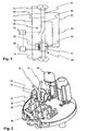
- FIG. 1 shows a test circuit of a residual current circuit breaker according to the invention.
- One first conductor 10 and a second conductor 11, for example phase (L) and neutral conductor (N), and a grounding conductor 12 connect a network-side terminal 13 and a consumer-side Output 14 of the residual current circuit breaker.
- the two conductors 10,11 lead by a measuring or summation current transformer 20, which is essentially a magnetic Core 21 and a secondary winding 22 includes.
- the latter is over a wiring 24 connected to a magnetic release 25 or actuator, which in turn the movable Contacts a switching point 26 controls.
- a test circuit 3 connects a first connection point 30 on the first conductor 10 with a second connection point 31 on the second conductor 11. It comprises a test button 32nd with a self-locking closing contact and a test circuit or test resistor 33 as well a scholarikaab gleich 34, which also by the summation current transformer 20th leads.
- FIG. 2 shows a detail of a residual current circuit breaker according to the invention.
- the test button 32 and the cut shown summation current transformer 20 is arranged on a board 40 (printed circuit board).
- the summation current transformer 20 comprises Furthermore, a converter shell 23, which is wound around the core 21 secondary winding 22 takes up.
- the test circuit resistor 33 connects two sections 35, 36 of the test circuit, which are printed as printed conductors on the board40.
- the two Ladder 10, 11 from one in Fig.2 the viewer facing consumer side to a Mains or supply side.
- the proposed invention has over one embodiment with a separate on the board 40 arranged test resistor fewer items and assembly steps on.
- an equippable, self-supporting für Vietnamese b gleiches 34 instead of limp wire loops or strands can be installed by automated placement machines are performed.
- the electrical insulation the für Vietnameserstandes 20 with respect to the current transformer 20 is through the converter shell 23 accomplished.
- the vertical distance of the für Vietnameserstandes is Current transformer 20 determined by the height of the converter shell 23 and dimensioned so that can be dispensed insulation of the legs of the strig Vietnameserstandes. It So can be used as a test resistor, a commercial resistance whose legs to the required Length are bent, are used.
- the residual current device is either as a fault-protected socket for the fixed Installation with a permanent wiring of the mains side connections provided or as a mobile fault-protected intermediate plug.
- the latter is on the network side equipped plug-in connections and in particular for retrofitting already existing suitable for electrical installations.
Landscapes
- Physics & Mathematics (AREA)
- General Physics & Mathematics (AREA)
- Breakers (AREA)
- Amplifiers (AREA)
- Emergency Protection Circuit Devices (AREA)
Description
- 10, 11
- Leiter
- 12
- Erdungsleiter
- 13
- Netzseitiger Anschluss
- 14
- Verbraucherseitiger Ausgang
- 20
- Summenstromwandler
- 21
- Kern
- 22
- Sekundärwicklung
- 23
- Wandlerschale
- 24
- Beschaltung
- 25
- Magnetauslöser
- 26
- Schaltstelle
- 3
- Prüfkreis
- 30
- Erster Anschlusspunkt
- 31
- Zweiter Anschlusspunkt
- 32
- Prüftaste mit Prüftastenfeder
- 33
- Prüfkreiswiderstand
- 34
- Prüfkreisabschluss
- 35, 36
- Prüfkreisabschnitt
- 40
- Platine
Claims (6)
- Prüfkreis (3) für Fehlerstromschutzgeräte mit einer durch eine Prüftaste (32) schliessbaren Kontaktstelle und einem Prüfkreiswiderstand (33), wobei
der Prüfkreis in einem ersten Anschlusspunkt (30) von einem ersten Leiter (10) abzweigt und in einem zweiten Anschlusspunkt (31) in einen zweiten Leiter (11) einmündet,
die beiden Leiter (10, 11) durch einen Summenstromwandler (20) geführt sind und einen Verbraucher mit einer Einspeisung verbinden,
bei geschlossener Kontaktstelle ein Fehlerstrom durch den Summenstromwandler (20) fliesst,
der erste und zweite Anschlusspunkt (30, 31) des Prüfkreises beide jeweils auf einer Verbraucher- oder Einspeiseseite des Summenstromwandlers (20) liegen,
der Summenstromwandler (20) auf einer Platine (40) angeordnet ist,
ein durch den Summenstromwandler (20) führender Prüfkreisabschluss (34) zwei auf die Platine (40) gedruckte Prüfkreisabschnitte (35, 36) verbindet, und
die beiden Leiter (10, 11) durch den Summenstromwandler (20) von einer Verbraucherseite zu einer Einspeiseseite der Platine (40) führen,
dadurch gekennzeichnet, dass
einer der beiden auf die Platine (40) gedruckten Prüfkreisabschnitte (35, 36) unter dem Summenstromwandler (20) durch in dessen Innenbereich führt. - Prüfkreis nach Anspruch 1, dadurch gekennzeichnet, dass der Prüfkreisabschluss (34) aus bestückungsfähigem Draht gefertigt ist.
- Prüfkreis nach Anspruch 2, dadurch gekennzeichnet, dass der Prüfkreisabschluss (34) den Prüfkreiswiderstand (33) umfasst.
- Prüfkreis nach Anspruch 2, dadurch gekennzeichnet, dass der Prüfkreisabschluss (34) den Summenstromwandler (20) nicht beführt.
- Prüfkreis nach Anspruch 1, dadurch gekennzeichnet, dass die beiden Leiter (10, 11) durch eine Ausnehmung in der Platine (40) hindurchgeführt sind.
- Fehlerstromschutzgerät mit einem Prüfkreis (3) nach einem der vorhergehenden Ansprüche.
Priority Applications (3)
| Application Number | Priority Date | Filing Date | Title |
|---|---|---|---|
| EP01810704A EP1275970B1 (de) | 2001-07-13 | 2001-07-13 | Prüfkreis für Fehlerstromschutzgeräte |
| DE50108386T DE50108386D1 (de) | 2001-07-13 | 2001-07-13 | Prüfkreis für Fehlerstromschutzgeräte |
| AT01810704T ATE313087T1 (de) | 2001-07-13 | 2001-07-13 | Prüfkreis für fehlerstromschutzgeräte |
Applications Claiming Priority (1)
| Application Number | Priority Date | Filing Date | Title |
|---|---|---|---|
| EP01810704A EP1275970B1 (de) | 2001-07-13 | 2001-07-13 | Prüfkreis für Fehlerstromschutzgeräte |
Publications (2)
| Publication Number | Publication Date |
|---|---|
| EP1275970A1 EP1275970A1 (de) | 2003-01-15 |
| EP1275970B1 true EP1275970B1 (de) | 2005-12-14 |
Family
ID=8184032
Family Applications (1)
| Application Number | Title | Priority Date | Filing Date |
|---|---|---|---|
| EP01810704A Expired - Lifetime EP1275970B1 (de) | 2001-07-13 | 2001-07-13 | Prüfkreis für Fehlerstromschutzgeräte |
Country Status (3)
| Country | Link |
|---|---|
| EP (1) | EP1275970B1 (de) |
| AT (1) | ATE313087T1 (de) |
| DE (1) | DE50108386D1 (de) |
Families Citing this family (1)
| Publication number | Priority date | Publication date | Assignee | Title |
|---|---|---|---|---|
| CN110108941A (zh) * | 2018-02-01 | 2019-08-09 | 金一凡 | 一种测量通电导体(导线)连接点接触阻抗的监测电路及方法 |
Family Cites Families (5)
| Publication number | Priority date | Publication date | Assignee | Title |
|---|---|---|---|---|
| DE3437527A1 (de) * | 1984-10-12 | 1986-04-17 | Patent-Treuhand-Gesellschaft für elektrische Glühlampen mbH, 8000 München | Anordnung von schaltungsbauteilen eines elektronischen vorschaltgeraetes zum betreiben einer niederdruckentladungslampe |
| DE3813403C2 (de) * | 1988-04-21 | 1994-12-08 | Felten & Guilleaume Energie | Ortsveränderlicher Differenzstromschalter |
| DE19634439A1 (de) * | 1996-08-26 | 1998-03-05 | Siemens Ag | Verfahren und Einrichtung zum Messen von Fehlerströmen |
| JP3843612B2 (ja) * | 1998-07-24 | 2006-11-08 | 松下電工株式会社 | プリント配線基板の零相変流器装着構造 |
| DE19857739A1 (de) * | 1998-12-15 | 2000-06-21 | Abb Patent Gmbh | Fehlerstromschutzschaltungsanordnung |
-
2001
- 2001-07-13 DE DE50108386T patent/DE50108386D1/de not_active Expired - Lifetime
- 2001-07-13 AT AT01810704T patent/ATE313087T1/de not_active IP Right Cessation
- 2001-07-13 EP EP01810704A patent/EP1275970B1/de not_active Expired - Lifetime
Also Published As
| Publication number | Publication date |
|---|---|
| EP1275970A1 (de) | 2003-01-15 |
| DE50108386D1 (de) | 2006-01-19 |
| ATE313087T1 (de) | 2005-12-15 |
Similar Documents
| Publication | Publication Date | Title |
|---|---|---|
| EP2107589B1 (de) | Schaltungsvorrichtung zur Erdung eines Wechselrichters | |
| DE60303341T2 (de) | Elektrische Steckverbinderanordnung mit Kurzschlusselement | |
| DE1130052B (de) | Selbsttaetige Sicherung zum Schutz elektrischer Verbraucher | |
| EP3226013A1 (de) | Differenzstromsensor | |
| DE102006059384B4 (de) | Gerät mit einem Stromwandler zur Erfassung eines durch einen Stromleiter fließenden Stromes sowie Klemmen-/Stromwandler-Modul für ein derartiges Gerät | |
| EP2883235A1 (de) | Stromwandler mit automatischer kurzschlussvorrichtung | |
| DE19712900A1 (de) | Sensoranordnung zur Strom- und Spannungsmessung | |
| DE102022115025A1 (de) | Vorrichtung zum Schutz gegen Überspannungen umfassend einem Sensor zur Strommessung | |
| DE69411086T2 (de) | Eine Erdschlusseinheit | |
| DE102015115410A1 (de) | Induktive Strommesswandlervorrichtung | |
| EP1266231B1 (de) | Messwandler | |
| DE102019202474A1 (de) | Fehlerstromschutzeinheit und Verfahren | |
| EP4099029A1 (de) | Elektrische schaltungsanordnung zur normgerechten isolationsüberwachung mit schnellabschaltung bei erdschlusserkennung für ein ungeerdetes stromversorgungssystem | |
| EP1275970A1 (de) | Prüfkreis für Fehlerstromschutzgeräte | |
| DE102011052449A1 (de) | Stromwandler sowie Lasttrenner mit einem solchen | |
| DE4445082C1 (de) | Hochspannungs-Steckkontakt | |
| DE69310424T2 (de) | Verbindungsblock für Mittelspannungsrelais mit Stromsensoren | |
| DE3784682T2 (de) | Wechselstromleistungsschaltkreis und sicherung dafuer. | |
| DE102018213519A1 (de) | Rogowskispule für einen Niederspannungsleistungsschalter | |
| WO2014040830A1 (de) | Stromwandler mit wechselkopf | |
| DE60118431T2 (de) | Elektrischer pol für einen niederspannungs-unterbrecherschalter | |
| AT521644B1 (de) | Vorrichtung zur Messung von Stromstärke und Spannung | |
| EP0249220A1 (de) | Schaltungsanordnung zum selbsttätigen Verbinden der Fernspeisestrompfade einer Fernspeiseschleife | |
| DE3844176A1 (de) | Verfahren zur erfassung eines zwischen einem phasen- und einem rueckleiter ueber den menschlichen koerper fliessenden stromes und zum abschalten der netzleiter | |
| DE2613972A1 (de) | Fehlerstromschutzschalter |
Legal Events
| Date | Code | Title | Description |
|---|---|---|---|
| PUAI | Public reference made under article 153(3) epc to a published international application that has entered the european phase |
Free format text: ORIGINAL CODE: 0009012 |
|
| AK | Designated contracting states |
Kind code of ref document: A1 Designated state(s): AT BE CH CY DE DK ES FI FR GB GR IE IT LI LU MC NL PT SE TR |
|
| AX | Request for extension of the european patent |
Free format text: AL;LT;LV;MK;RO;SI |
|
| 17P | Request for examination filed |
Effective date: 20030523 |
|
| AKX | Designation fees paid |
Designated state(s): AT BE CH CY DE DK ES FI FR GB GR IE IT LI LU MC NL PT SE TR |
|
| 17Q | First examination report despatched |
Effective date: 20040528 |
|
| GRAP | Despatch of communication of intention to grant a patent |
Free format text: ORIGINAL CODE: EPIDOSNIGR1 |
|
| GRAS | Grant fee paid |
Free format text: ORIGINAL CODE: EPIDOSNIGR3 |
|
| GRAA | (expected) grant |
Free format text: ORIGINAL CODE: 0009210 |
|
| AK | Designated contracting states |
Kind code of ref document: B1 Designated state(s): AT BE CH CY DE DK ES FI FR GB GR IE IT LI LU MC NL PT SE TR |
|
| PG25 | Lapsed in a contracting state [announced via postgrant information from national office to epo] |
Ref country code: IT Free format text: LAPSE BECAUSE OF FAILURE TO SUBMIT A TRANSLATION OF THE DESCRIPTION OR TO PAY THE FEE WITHIN THE PRESCRIBED TIME-LIMIT;WARNING: LAPSES OF ITALIAN PATENTS WITH EFFECTIVE DATE BEFORE 2007 MAY HAVE OCCURRED AT ANY TIME BEFORE 2007. THE CORRECT EFFECTIVE DATE MAY BE DIFFERENT FROM THE ONE RECORDED. Effective date: 20051214 Ref country code: IE Free format text: LAPSE BECAUSE OF FAILURE TO SUBMIT A TRANSLATION OF THE DESCRIPTION OR TO PAY THE FEE WITHIN THE PRESCRIBED TIME-LIMIT Effective date: 20051214 Ref country code: GB Free format text: LAPSE BECAUSE OF FAILURE TO SUBMIT A TRANSLATION OF THE DESCRIPTION OR TO PAY THE FEE WITHIN THE PRESCRIBED TIME-LIMIT Effective date: 20051214 Ref country code: FI Free format text: LAPSE BECAUSE OF FAILURE TO SUBMIT A TRANSLATION OF THE DESCRIPTION OR TO PAY THE FEE WITHIN THE PRESCRIBED TIME-LIMIT Effective date: 20051214 Ref country code: NL Free format text: LAPSE BECAUSE OF FAILURE TO SUBMIT A TRANSLATION OF THE DESCRIPTION OR TO PAY THE FEE WITHIN THE PRESCRIBED TIME-LIMIT Effective date: 20051214 |
|
| REG | Reference to a national code |
Ref country code: GB Ref legal event code: FG4D Free format text: NOT ENGLISH |
|
| REG | Reference to a national code |
Ref country code: CH Ref legal event code: EP |
|
| REG | Reference to a national code |
Ref country code: IE Ref legal event code: FG4D Free format text: LANGUAGE OF EP DOCUMENT: GERMAN |
|
| REF | Corresponds to: |
Ref document number: 50108386 Country of ref document: DE Date of ref document: 20060119 Kind code of ref document: P |
|
| PG25 | Lapsed in a contracting state [announced via postgrant information from national office to epo] |
Ref country code: DK Free format text: LAPSE BECAUSE OF FAILURE TO SUBMIT A TRANSLATION OF THE DESCRIPTION OR TO PAY THE FEE WITHIN THE PRESCRIBED TIME-LIMIT Effective date: 20060314 Ref country code: SE Free format text: LAPSE BECAUSE OF FAILURE TO SUBMIT A TRANSLATION OF THE DESCRIPTION OR TO PAY THE FEE WITHIN THE PRESCRIBED TIME-LIMIT Effective date: 20060314 Ref country code: GR Free format text: LAPSE BECAUSE OF FAILURE TO SUBMIT A TRANSLATION OF THE DESCRIPTION OR TO PAY THE FEE WITHIN THE PRESCRIBED TIME-LIMIT Effective date: 20060314 |
|
| PG25 | Lapsed in a contracting state [announced via postgrant information from national office to epo] |
Ref country code: ES Free format text: LAPSE BECAUSE OF FAILURE TO SUBMIT A TRANSLATION OF THE DESCRIPTION OR TO PAY THE FEE WITHIN THE PRESCRIBED TIME-LIMIT Effective date: 20060325 |
|
| PG25 | Lapsed in a contracting state [announced via postgrant information from national office to epo] |
Ref country code: PT Free format text: LAPSE BECAUSE OF FAILURE TO SUBMIT A TRANSLATION OF THE DESCRIPTION OR TO PAY THE FEE WITHIN THE PRESCRIBED TIME-LIMIT Effective date: 20060515 |
|
| NLV1 | Nl: lapsed or annulled due to failure to fulfill the requirements of art. 29p and 29m of the patents act | ||
| GBV | Gb: ep patent (uk) treated as always having been void in accordance with gb section 77(7)/1977 [no translation filed] |
Effective date: 20051214 |
|
| REG | Reference to a national code |
Ref country code: IE Ref legal event code: FD4D |
|
| PG25 | Lapsed in a contracting state [announced via postgrant information from national office to epo] |
Ref country code: BE Free format text: LAPSE BECAUSE OF NON-PAYMENT OF DUE FEES Effective date: 20060731 Ref country code: MC Free format text: LAPSE BECAUSE OF NON-PAYMENT OF DUE FEES Effective date: 20060731 Ref country code: CH Free format text: LAPSE BECAUSE OF NON-PAYMENT OF DUE FEES Effective date: 20060731 Ref country code: LI Free format text: LAPSE BECAUSE OF NON-PAYMENT OF DUE FEES Effective date: 20060731 |
|
| ET | Fr: translation filed | ||
| PLBE | No opposition filed within time limit |
Free format text: ORIGINAL CODE: 0009261 |
|
| STAA | Information on the status of an ep patent application or granted ep patent |
Free format text: STATUS: NO OPPOSITION FILED WITHIN TIME LIMIT |
|
| 26N | No opposition filed |
Effective date: 20060915 |
|
| REG | Reference to a national code |
Ref country code: CH Ref legal event code: PL |
|
| PG25 | Lapsed in a contracting state [announced via postgrant information from national office to epo] |
Ref country code: AT Free format text: LAPSE BECAUSE OF NON-PAYMENT OF DUE FEES Effective date: 20060713 |
|
| BERE | Be: lapsed |
Owner name: ABB SCHWEIZ A.G. Effective date: 20060731 |
|
| PG25 | Lapsed in a contracting state [announced via postgrant information from national office to epo] |
Ref country code: LU Free format text: LAPSE BECAUSE OF NON-PAYMENT OF DUE FEES Effective date: 20060713 Ref country code: TR Free format text: LAPSE BECAUSE OF FAILURE TO SUBMIT A TRANSLATION OF THE DESCRIPTION OR TO PAY THE FEE WITHIN THE PRESCRIBED TIME-LIMIT Effective date: 20051214 |
|
| PG25 | Lapsed in a contracting state [announced via postgrant information from national office to epo] |
Ref country code: CY Free format text: LAPSE BECAUSE OF FAILURE TO SUBMIT A TRANSLATION OF THE DESCRIPTION OR TO PAY THE FEE WITHIN THE PRESCRIBED TIME-LIMIT Effective date: 20051214 |
|
| REG | Reference to a national code |
Ref country code: FR Ref legal event code: PLFP Year of fee payment: 15 |
|
| PGFP | Annual fee paid to national office [announced via postgrant information from national office to epo] |
Ref country code: FR Payment date: 20150626 Year of fee payment: 15 |
|
| PGFP | Annual fee paid to national office [announced via postgrant information from national office to epo] |
Ref country code: DE Payment date: 20150721 Year of fee payment: 15 |
|
| REG | Reference to a national code |
Ref country code: DE Ref legal event code: R119 Ref document number: 50108386 Country of ref document: DE |
|
| PG25 | Lapsed in a contracting state [announced via postgrant information from national office to epo] |
Ref country code: FR Free format text: LAPSE BECAUSE OF NON-PAYMENT OF DUE FEES Effective date: 20160801 Ref country code: DE Free format text: LAPSE BECAUSE OF NON-PAYMENT OF DUE FEES Effective date: 20170201 |
|
| REG | Reference to a national code |
Ref country code: FR Ref legal event code: ST Effective date: 20170331 |