EP1275900B1 - Spiegellamelle für entblendete Leuchten - Google Patents
Spiegellamelle für entblendete Leuchten Download PDFInfo
- Publication number
- EP1275900B1 EP1275900B1 EP02090237A EP02090237A EP1275900B1 EP 1275900 B1 EP1275900 B1 EP 1275900B1 EP 02090237 A EP02090237 A EP 02090237A EP 02090237 A EP02090237 A EP 02090237A EP 1275900 B1 EP1275900 B1 EP 1275900B1
- Authority
- EP
- European Patent Office
- Prior art keywords
- reflecting
- lamella
- foregoing
- lamella according
- inner edge
- Prior art date
- Legal status (The legal status is an assumption and is not a legal conclusion. Google has not performed a legal analysis and makes no representation as to the accuracy of the status listed.)
- Expired - Lifetime
Links
- 230000004313 glare Effects 0.000 title description 6
- 241000446313 Lamella Species 0.000 claims description 49
- 230000000087 stabilizing effect Effects 0.000 claims description 8
- 239000000463 material Substances 0.000 claims description 4
- 238000001746 injection moulding Methods 0.000 claims description 3
- 239000004417 polycarbonate Substances 0.000 claims description 3
- 229920000515 polycarbonate Polymers 0.000 claims description 3
- 239000004033 plastic Substances 0.000 claims description 2
- BHMLFPOTZYRDKA-IRXDYDNUSA-N (2s)-2-[(s)-(2-iodophenoxy)-phenylmethyl]morpholine Chemical compound IC1=CC=CC=C1O[C@@H](C=1C=CC=CC=1)[C@H]1OCCNC1 BHMLFPOTZYRDKA-IRXDYDNUSA-N 0.000 claims 1
- 239000011248 coating agent Substances 0.000 claims 1
- 238000000576 coating method Methods 0.000 claims 1
- 230000007774 longterm Effects 0.000 claims 1
- 230000005855 radiation Effects 0.000 description 14
- 238000010586 diagram Methods 0.000 description 8
- 230000000694 effects Effects 0.000 description 2
- 238000004519 manufacturing process Methods 0.000 description 2
- XAGFODPZIPBFFR-UHFFFAOYSA-N aluminium Chemical compound [Al] XAGFODPZIPBFFR-UHFFFAOYSA-N 0.000 description 1
- 229910052782 aluminium Inorganic materials 0.000 description 1
- 230000001419 dependent effect Effects 0.000 description 1
- 238000004512 die casting Methods 0.000 description 1
- 238000009826 distribution Methods 0.000 description 1
- 238000005265 energy consumption Methods 0.000 description 1
- 238000005516 engineering process Methods 0.000 description 1
- 230000004907 flux Effects 0.000 description 1
- 238000002310 reflectometry Methods 0.000 description 1
- 239000007787 solid Substances 0.000 description 1
Images




Classifications
-
- F—MECHANICAL ENGINEERING; LIGHTING; HEATING; WEAPONS; BLASTING
- F21—LIGHTING
- F21V—FUNCTIONAL FEATURES OR DETAILS OF LIGHTING DEVICES OR SYSTEMS THEREOF; STRUCTURAL COMBINATIONS OF LIGHTING DEVICES WITH OTHER ARTICLES, NOT OTHERWISE PROVIDED FOR
- F21V11/00—Screens not covered by groups F21V1/00, F21V3/00, F21V7/00 or F21V9/00
- F21V11/02—Screens not covered by groups F21V1/00, F21V3/00, F21V7/00 or F21V9/00 using parallel laminae or strips, e.g. of Venetian-blind type
-
- F—MECHANICAL ENGINEERING; LIGHTING; HEATING; WEAPONS; BLASTING
- F21—LIGHTING
- F21V—FUNCTIONAL FEATURES OR DETAILS OF LIGHTING DEVICES OR SYSTEMS THEREOF; STRUCTURAL COMBINATIONS OF LIGHTING DEVICES WITH OTHER ARTICLES, NOT OTHERWISE PROVIDED FOR
- F21V13/00—Producing particular characteristics or distribution of the light emitted by means of a combination of elements specified in two or more of main groups F21V1/00 - F21V11/00
- F21V13/02—Combinations of only two kinds of elements
- F21V13/10—Combinations of only two kinds of elements the elements being reflectors and screens
-
- F—MECHANICAL ENGINEERING; LIGHTING; HEATING; WEAPONS; BLASTING
- F21—LIGHTING
- F21W—INDEXING SCHEME ASSOCIATED WITH SUBCLASSES F21K, F21L, F21S and F21V, RELATING TO USES OR APPLICATIONS OF LIGHTING DEVICES OR SYSTEMS
- F21W2131/00—Use or application of lighting devices or systems not provided for in codes F21W2102/00-F21W2121/00
- F21W2131/10—Outdoor lighting
- F21W2131/103—Outdoor lighting of streets or roads
Definitions
- the invention relates to a mirror slat for glare control of lights with a annular lamellar body with a concavely curved in the radial planes Ring surface that of a circular inner edge and a circular
- the outer edge is limited, the diameter of the inner edge being smaller than that Diameter of the outer edge and the surface of the lamellar body with a reflective material is provided, the mirror lamella with at least one perpendicular to the plane of the reflector defined by the inner edge is provided.
- Such mirror slats are used to glare large light sources in Lights used.
- the lights can also be found as street or Path lighting use.
- the lamellae are ring-shaped and become ordinary placed on one another.
- the rings usually have a frustoconical or concave curved mirrored ring surface. The light emitted by the light source can then exit diagonally downwards only in certain directions, so that the Example drivers are not dazzled.
- a disadvantage of the known lamella arrangements is that the light is always is radiated radially around the lamp. The residents of a street can are disturbed by the light emitted by a street lamp in their direction.
- a lampshade for a street or square light in which a plurality of slats are arranged one above the other.
- a mirror reflector cuts the slats in segments.
- the specular reflector extends over the entire Height of the arrangement.
- the use of the mirror reflector creates an asymmetrical one Light distribution.
- the mirror reflector consists of one piece and is by means of screws or rivets attached to the top and bottom slats.
- the object is achieved in that the reflector surface is curved or faceted and the slat body with the reflector surface in one Piece is made .. This way one direction can be completely dimmed and that Light can be directed in another desired direction. It will be asymmetrical Lighting reached.
- the reflector surface is curved. It is preferred Parabolically curved reflector surface.
- Two meeting Reflector surfaces preferably form a larger angle with one another than the two other reflector surfaces.
- the reflector surfaces that make the larger angle with each other can be arranged, for example, in the direction of the residential side of a street be so that a larger dimming is achieved here.
- the reflector surfaces preferably describe a parabola, the axis of symmetry thereof forms a non-zero angle with the straight line through the vertex, which is perpendicular to the diameter that connects the axes on which the Reflector surfaces meet. Surprisingly, it has been shown that this is a causes particularly good alignment of the radiation.
- the reflector surfaces each belonging to a pair of reflector surfaces point in one preferred embodiment, the same curvature. This will introduce the Asymmetry the same on both sides.
- the reflector surfaces can have an upper edge in the plane of the inner edge of the Have lamellar body, and at least a part of each reflector surface can on the Side of the parabolically shaped surface of the lamellar body can be arranged.
- the reflector surfaces can have a lower one Have edge in the plane of the outer edge of the slat body and at least one Part of each reflector surface on that of the parabolically shaped surface opposite side of the slat body may be arranged. Both parts of the Reflector surface help to align the radiation and dazzle.
- the lamella can be stackable. Passages are preferably provided, which at stacked mirror slats are arranged one above the other and through which one Fastening element can be pushed through for fastening the mirror slats with each other and / or for fastening the mirror slats to a holder. Then can the slats can be easily stacked on top of each other.
- the passages can be arranged around the axes at which the reflector surfaces meet.
- a projection is preferably provided on one edge of each reflector surface and a groove on the opposite edge of the reflector surface, the Head start in the groove of one with stacked mirror slats engaging adjacent mirror slat. This makes the slats stackable improves and the orientation of the angle at which the slats are stacked around the common central axis lie, simplified.
- At least one stabilizing pin is provided, which is perpendicular to the through the plane defined by the inner edge. This will cause the slats to tilt against each other and the stability of the stacked slats improved.
- the surface is on the concave curved ring surface opposite side of the lamellar body stepped. This will make the number of reflections needed for everyone Light beam minimizes and prevents light from emerging horizontally or upwards.
- the steps are preferably in the direction of the outer edge of the lamellar body flatter and have a larger angle. This will cause a slight fluctuation in thickness the slat reached. Thickness fluctuations can lead to the Manufacture the still hot material in the thick areas of the slat body more contracts than in the thinner places. The effect causes sink marks on the Top of the slats, which can affect the quality of the direction of reflection.
- the smallest angle of the steps on the inner edge of the lamellar body is preferably about 90 degrees and the largest angle of the steps on the outer edge of the slat body about 120 degrees. A particularly good radiation quality is achieved with this angular range the directions reached.
- the lamella can be made from an injection molding process Polycarbonate exist. But it can also be made of temperature-resistant plastic a continuous use temperature up to 180 ° C if this is due to high Luminosity with the corresponding high temperatures is necessary. It is still it is possible to manufacture the slats from die-cast aluminum using die-casting technology.
- a particularly good reflectivity is achieved if the lamella is coated with a primer is provided and they as a whole with a reflective vaporized in a high vacuum Layer is provided.
- Embodiments of the invention are the subject of the dependent claims. Embodiments of the invention are below with reference to the attached drawings explained in more detail.
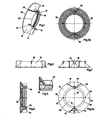
- 10 denotes a mirror slat.
- the mirror slat 10 includes one Lamella body 12, four reflector surfaces 14, 16, 18 and 20 and two stabilizing pins 22 and 24.
- the lamellar body 12 is annular with an annular outer edge 26 and an annular inner edge 28.
- Fig. 2 is the position of the four reflector surfaces 14, 16, 18 and 20 and the stabilizing pins 22 and 24 shown again with respect to the lamellar body 12.
- the reflector surfaces 14, 16, 18 and 20 extend from the inner edge 28 to the outer edge 26 of the Lamellar body.
- the reflector surfaces 18 and 20 meet on an axis 30 on the Inner edge 26 on top of each other.
- the axis 30 is perpendicular to the paper plane in Fig.2.
- At the opposite end of the diameter 32 belonging to the axis 30 is one Axis 34 on which the reflector surfaces 14 and 16 meet.
- the reflector surfaces 14, 16, 18 and 20 are curved parabolically.
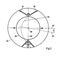
- the to the Parabola 36 belonging to reflector surface 20 is shown in FIG.
- the center of curvature the parabola 36 lies in the common center 38 of the inner ring 28 and outer ring 26.
- the axis of symmetry 42 of the parabola 36 forms an angle of 10 ° with that on the Diameter 32 straight lines 40.
- the opening of the to the Reflector surface 20 associated parabola 36 is the same as the opening of the to Reflector surface 18 belonging parabola. However, the orientation of the reflector surface is on mirrored the diameter 32.
- the opening of the parabola 36 is larger than the opening of the reflector surfaces 14 and 16 belonging parabola.
- the parabola 44 belonging to the reflector surface 14 is shown in FIG shown.
- This parabola 44 has an axis of symmetry 46 which forms an angle with forms the axis 40 of 20 °.
- the reflector surface 16 is symmetrical to that Reflector surface 14 formed around the diameter 32.
- a mark 48 on the top of the slat body between the two Reflector surfaces 14 and 16 indicate the direction of the road to align the Lighten slat. Openings or are close to the axes 34 and 36 Bores 50 and 52 are provided. The holes are in the sectional drawings of 5 and 6 and in the side view in Fig.7 shown again in detail.
- the Bores 50 and 52 lie in the lamellar body 12 and each end in one cylindrical extension 54 which extends up to the height of the inner edge 28 of the Slat body extends.
- the inside diameter of the cylindrical extension 54 is less than the diameter of the bore 50.
- two stabilizing pins 22 and 24 are on the axis 40 intended.
- the pins are again in the side view in Fig. 8 and in Fig. 6 in Section shown. They extend from the height of the inner edge 28 to the height of the Outer edges 26 and are solid. With stacked slats they prevent Tilt around axis 32.
- the stabilizing pins 20, 22 form next to the top and bottom sides of the reflector surfaces 14, 16, 18 and 20 and the extensions 54 further support points when stacking the Slats 10.
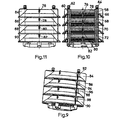
- the stacked slats are shown in FIGS. 9-11.
- the Fastening elements 58 and 60 protrude through all four lamella bodies 66, 68, 70 and 74 and are screwed together using screws 62 and 64.
- the stabilizing pins 76, 78, 80 and 82 rest on each other.
- the reflector surfaces, for example 84, 86, 88, 90 referred to, and the extensions 92, 94, 96 and 98 lie on each other. (Fig. 9).
- the Lamellar bodies 66, 68, 70 and 74 themselves, however, have no common Support points or areas.
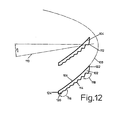
- FIG. 1 A section through a lamellar body 12, e.g. along a section line 100 in FIG. 2 is shown in FIG.
- Lamellar bodies 102 and 104 are shown.
- the surface 106 of the slat bodies 102, 104 is curved parabolically.
- the parabola 108 belonging to the surface 106 is shown in FIG also shown.
- the axis of symmetry 110 of the parabola 108 forms with the horizontal, i.e. with the straight line that is perpendicular to the stacking direction Angle of 10 °.
- the center of curvature 112 of the parabola 108 lies on the inner one lower edge of the slat body 104 of the one located above the slat body 106 Lamella.
- the underside 114 of the slat body 106 is designed in a step-like manner.
- the angles 116, 118 of steps 120 increase from inside 122 to outside 124. So is the smallest angle 118 is approximately 90 ° and the largest angle on the outside is approximately 120 °. Together with the shown curvature of the top, this creates a beam path achieved as shown in Fig. 13.
- the one from a point of light on the inner bottom Radiation emitted from the edge of the upper lamellar body is schematic in FIG. 13 shown. Beams 126, 128, 130 and 132 are emitted directly to the outside. The remaining rays 134 are reflected to the outside with only one reflection on the surface 106 radiated.
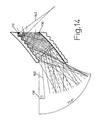
- Fig. 14 the beam profiles of light points are shown similar to Fig. 13.
- the dashed ones Rays show the beam path belonging to light point 112, and the solid lines the beam path belonging to light point 136.
- straight line 138 Only a few rays 140 are in an area radiated by 5 °. All rays leave the arrangement with angles between 5 ° and 75.8 °. Only a small proportion 142 of the rays are directed into the lamp reflected back. However, this is not harmful to the overall result.
- the polar diagram of the lamp described is shown in FIG. In it the radiated intensity in kd / Klm depending on the radiation angle ⁇ .
- the Angle ⁇ is the angle that a beam forms with the vertical. As at the beginning radiation in the horizontal direction at 90 ° is undesirable and a high radiation at about 60 ° is aimed for.
- the polar diagram is for four shown different directions.
- the direction labeled C0-C180 runs parallel to the axis labeled 40 in FIG.
- the axis labeled C90-C270 runs parallel to the axis designated 32 in FIG. 2.
- the associated Isolux diagram is shown in FIG. 16.
- the intensity is shown depending on the horizontal position.
- a street for example, would go from right to left in Fig. 16 and the resident side could be arranged below in this example.
- the Reflector surfaces 14, 16, 18, and 20 become a deviation from the rotational symmetry reached.
- the diagram clearly shows that the "range" of the lamp is towards along the street has become larger and smaller in the direction of the residents. Thereby the lamps can be spaced from each other, resulting in cost and Energy savings.
- the slats are made of polycarbonate in one piece by injection molding. She are pre-painted and vaporized with reflective material in a high vacuum.
Landscapes
- Engineering & Computer Science (AREA)
- General Engineering & Computer Science (AREA)
- Optical Elements Other Than Lenses (AREA)
Description
- Fig. 1
- ist eine dreidimensionale Darstellung einer Spiegellamelle
- Fig.2a
- zeigt ein Draufsicht von oben auf eine Spiegellamelle
- Fig.2b
- zeigt ein Draufsicht von unten auf eine Spiegellamelle
- Fig.3
- entspricht Fig.2a ergänzt um eine Parabel, die eine Reflektorfläche beschreibt
- Fig.4
- entspricht Fig.3, mit einer Parabel, die eine andere Reflektorfläche beschreibt.
- Fig.5
- zeigt einen Querschnitt durch einen Teil einer Spiegellamelle, der eine Bohrung umfasst
- Fig.6
- zeigt einen Querschnitt durch eine komplette Spiegellamelle
- Fig.7
- zeigt eine Seitenansicht einer Spiegellamelle, bei der ein zylindrischer Fortsatz einer Bohrung sichtbar ist.
- Fig.8
- zeigt eine Seitenansicht einer Spiegellamelle, bei der ein Stabilisierstift sichtbar ist.
- Fig.9
- ist eine dreidimensionale Ansicht von aufeinandergestapelten und miteinander befestigten Spiegellamellen
- Fig.10
- ist ein Schnitt durch die Anordnung aus Fig.9
- Fig.11
- ist eine Seitenansicht auf die Anordnung aus Fig.9
- Fig.12
- ist ein Schnitt durch einen Lamellenkörper entlang einer Achse 100 in Fig.2a
- Fig.13
- zeigt die Anordnung aus Fig.12 mit eingezeichnetem Strahlengang für Strahlung aus einem Lichtpunkt
- Fig.14
- zeigt die Anordnung aus Fig.12 mit eingezeichnetem Strahlengang für Strahlung aus zwei Lichtpunkten
- Fig.15
- ist ein Polardiagramm für eine Leuchte mit einer Spiegellamellenanordnung
- Fig.16
- ist das zu dem Polardiagramm aus Fig.15 gehörige Isoluxdiagramm derselben Leuchte.
Claims (20)
- Spiegellamelle (10) zur Entblendung von Leuchten mit einem ringförmigen Lamellenkörper (12) mit einer Ringoberfläche (106), die von einem kreisförmigen Innenrand (28) und einem kreisförmigen Außenrand (26) begrenzt ist, wobei der Durchmesser (32) des Innenrands (28) kleiner ist als der Durchmesser des Außenrands (26) und wobei die Spiegllamelle (10) mit wenigstens einer senkrecht zu der durch den Innenrand (28) definierten Ebene verlaufenden, gekrümmt oder facettiert gekanteten Reflektorfläche (14, 16, 18, 20) versehen ist, dadurch gekennzeichnet, daß die Spiegellamelle (10) in einem Stück gefertigt ist, die Ringoberfläche in den Radialebenen konkav gekrümmt ist, und die Oberfläche (106) des Lamellenkörpers (12) mit einem reflektierenden Material versehen ist.
- Spiegellamelle nach Anspruch 1, dadurch gekennzeichnet, daß die Reflektorfläche (14, 16, 18, 20) parabolisch gekrümmt ist.
- Spiegellamelle nach einem der vorgehenden Ansprüche, dadurch gekennzeichnet, daß zwei Reflektorflächen (14,16; 18, 20) vorgesehen sind, die auf einer senkrecht zu der durch den Innenrand (28) definierten Ebene verlaufenden Achse (30; 34) zusammentreffen.
- Spiegellamelle nach Anspruch 3, dadurch gekennzeichnet, daß vier Reflektorflächen (14, 16, 18, 20) vorgesehen sind, die paarweise auf jeweils einer senkrecht der durch den Innenrand (28) definierten Ebene verlaufenden Achse (30, 34) zusammentreffen und die beiden Achsen (39, 34) auf einem Durchmesser (32) und dem Innenrand (28) der Ringoberfläche des Lammellenkörpers (12) liegen.
- Spiegellamelle nach Anspruch 4, dadurch gekennzeichnet, daß zwei zusammentreffende Reflektorflächen (18, 20) einen größeren Winkel miteinander bilden als die beiden anderen Reflektorflächen (14, 16).
- Spiegellamelle nach einem der Ansprüche 3 bis 5, dadurch gekennzeichnet, daß die Reflektorflächen (14, 16, 18, 20) eine Parabel (36, 44) beschreiben, deren Symmetrieachse (42, 46) durch den Scheitelpunkt einen von Null verschiedenen Winkel mit der Geraden (40) bildet, die senkrecht auf dem Durchmesser (32) steht, der die Achsen (30, 34) verbindet, auf denen die Reflektorflächen (14,16; 18, 20) zusammentreffen.
- Spiegellamelle nach einem der Ansprüche 3 bis 5, dadurch gekennzeichnet, daß die jeweils zu einem Reflektorflächenpaar (14, 16; 18, 20) gehörigen Reflektorflächen die gleiche Krümmung aufweisen.
- Spiegellamelle nach einem der vorgehenden Ansprüche, dadurch gekennzeichnet, daß die Reflektorflächen (14, 16, 18, 20) einen oberen Rand in der Ebene des Innenrands (28) des Lamellenkörpers (12) aufweisen, und wenigstens ein Teil jeder Reflektorfläche (14, 16, 18, 20) auf der Seite der parabolisch geformten Oberfläche (106) des Lamellenkörpers (12) angeordnet ist.
- Spiegellamelle nach einem der vorgehenden Ansprüche, dadurch gekennzeichnet, daß die Reflektorflächen (14, 16, 18, 20) einen unteren Rand in der Ebene des Außenrands (26) des Lamellenkörpers (12) aufweisen und wenigstens ein Teil jeder Reflektorfläche auf der der parabolisch geformten Oberfläche (106) entgegengesetzten Seite (114) des Lamellenkörpers (12) angeordnet ist.
- Spiegellamelle nach einem der vorgehenden Ansprüche, dadurch gekennzeichnet, daß sie stapelbar ist.
- Spiegellamelle nach Anspruch 10, gekennzeichnet durch Durchgänge (50, 52), die bei gestapelten Spiegellamellen (66, 68, 70, 72) übereinander angeordnet sind und durch welche ein Befestigungselement (60, 64) hindurchsteckbar ist zur Befestigung der Spiegellamellen miteinander und/oder zur Befestigung der Spiegellamellen an einem Halter.
- Spiegellamelle nach Anspruch 10 oder 11, gekennzeichnet durch einen Vorsprung auf dem einen Rand jeder Reflektorfläche und einer Rille auf dem gegenüberliegenden Rand der Reflektorfläche, wobei der Vorsprung bei aufeinandergestapelten Spiegellamellen in die Rille einer daran angrenzenden Spiegellamelle eingreift.
- Spiegellamelle nach einem der vorgehenden Ansprüche, gekennzeichnet durch wenigstens einen Stabilisierstift (22, 24,76, 78, 80, 82), senkrecht zu der durch den Innenrand (28) definierten Ebene.
- Spiegellamelle nach einem der vorgehenden Ansprüche, dadurch gekennzeichnet daß die Oberfläche (114) auf der der konkav gekrümmten Ringoberfläche (106) entgegengesetzte Seite des Lamellenkörpers (12) stufenförmig ausgebildet ist.
- Spiegellamelle nach Anspruch 14, dadurch gekennzeichnet, daß die Stufen (120) in Richtung des Außenrands (124) des Lamellenkörpers (12) flacher werden und einen größeren Winkel (116) haben.
- Spiegellamelle nach Anspruch 15, dadurch gekennzeichnet, daß der kleinste Winkel (118) der Stufen am Innenrand (28) des Lamellenkörpers (12) 90 Grad und der größte Winkel (116) der Stufen (120) am Außenrand (124) des Lamellenkörpers (12) 120 Grad beträgt
- Spiegellamelle nach einem der vorgehenden Ansprüche, dadurch gekennzeichnet, daß sie aus im Spritzgußverfahren verarbeitbarem Polycarbonat besteht.
- Spiegellamelle nach einem der Ansprüche 1 bis 16, dadurch gekennzeichnet, daß sie aus temperaturbeständigem Kunststoff mit einer Dauergebrauchstemperatur bis 180 °C besteht.
- Spiegellamelle nach einem der vorgehenden Ansprüche, dadurch gekennzeichnet, daß sie mit einem Vorlack versehen ist.
- Spiegellamelle nach einem der vorgehenden Ansprüche, dadurch gekennzeichnet, daß sie als ganzes mit einer im Hochvakuum bedampfbaren, reflektierenden Schicht versehen ist.
Applications Claiming Priority (2)
| Application Number | Priority Date | Filing Date | Title |
|---|---|---|---|
| DE10133578 | 2001-07-13 | ||
| DE10133578A DE10133578A1 (de) | 2001-07-13 | 2001-07-13 | Spiegellamelle für entblendete Leuchten |
Publications (2)
| Publication Number | Publication Date |
|---|---|
| EP1275900A1 EP1275900A1 (de) | 2003-01-15 |
| EP1275900B1 true EP1275900B1 (de) | 2004-05-12 |
Family
ID=7691334
Family Applications (1)
| Application Number | Title | Priority Date | Filing Date |
|---|---|---|---|
| EP02090237A Expired - Lifetime EP1275900B1 (de) | 2001-07-13 | 2002-07-09 | Spiegellamelle für entblendete Leuchten |
Country Status (2)
| Country | Link |
|---|---|
| EP (1) | EP1275900B1 (de) |
| DE (2) | DE10133578A1 (de) |
Families Citing this family (1)
| Publication number | Priority date | Publication date | Assignee | Title |
|---|---|---|---|---|
| JP6101373B2 (ja) * | 2016-01-28 | 2017-03-22 | 京セラ株式会社 | 発光部および閃光発光装置 |
Family Cites Families (6)
| Publication number | Priority date | Publication date | Assignee | Title |
|---|---|---|---|---|
| US3371201A (en) * | 1964-12-16 | 1968-02-27 | Joslyn Mfg & Supply Co | Luminaire |
| US3390263A (en) * | 1966-08-22 | 1968-06-25 | Willis L. Lipscomb | Columnar cellular louver light control unit |
| DE2901847A1 (de) * | 1979-01-18 | 1980-08-07 | Sommer Horst | Vorrichtung zum keimfreimachen der luft unter verwendung eines vertikal angeordneten stabfoermigen uv-strahlers |
| AT374258B (de) * | 1982-10-18 | 1984-04-10 | Zumtobel Ag | Raster fuer leuchtstofflampenleuchten |
| US4814961A (en) * | 1987-12-21 | 1989-03-21 | The Toro Company | Light fixture |
| DE9103102U1 (de) * | 1991-03-14 | 1991-06-13 | Hess Form + Licht GmbH + Co, 7730 Villingen-Schwenningen | Lampenschirm für eine Straßen- oder Platzleuchte |
-
2001
- 2001-07-13 DE DE10133578A patent/DE10133578A1/de not_active Withdrawn
-
2002
- 2002-07-09 EP EP02090237A patent/EP1275900B1/de not_active Expired - Lifetime
- 2002-07-09 DE DE50200428T patent/DE50200428D1/de not_active Expired - Fee Related
Also Published As
| Publication number | Publication date |
|---|---|
| DE10133578A1 (de) | 2003-01-30 |
| DE50200428D1 (de) | 2004-06-17 |
| EP1275900A1 (de) | 2003-01-15 |
Similar Documents
| Publication | Publication Date | Title |
|---|---|---|
| EP2729838B1 (de) | Optisches element | |
| DE3341773C2 (de) | Abblendlichtscheinwerfer | |
| DE19910192C2 (de) | Reflektor mit einem konkaven rotationssymmetrischen Grundkörper und einer Facetten aufweisenden Reflexionsfläche | |
| DE2144300A1 (de) | Reflektor | |
| WO2001011286A1 (de) | Scheinwerfer | |
| EP2518398B1 (de) | Anordnung zur veränderbaren Lichtabgabe | |
| EP3165818B1 (de) | Innen- oder aussenleuchte, insbesondere strassenleuchte, mit verlagerbarer freiformlinse | |
| EP2472177A2 (de) | Leuchte | |
| DE4414742A1 (de) | Leuchte mit mindestens einem ringförmigen Leuchtmittel | |
| WO2004097293A1 (de) | Träger für eine leuchte sowie leuchtenkopf mit einem träger und einem reflektor | |
| EP1275900A1 (de) | Spiegellamelle für entblendete Leuchten | |
| EP2320129B1 (de) | Reflektorleuchte | |
| EP1770329A2 (de) | Anordnung zum gezielten Entblenden von Außenleuchten in vertikaler und horizontaler Achse | |
| DE102010014210A1 (de) | Linienförmige LED-Leuchte, insbesondere LED-Ringleuchte | |
| EP1900998B1 (de) | Reflektor mit einer lichtaufweitenden Struktur | |
| DE3836282C2 (de) | Leuchte mit einer Lampen-Reflektor-Einheit zur Aufhellung von Deckenbereichen | |
| DE102009058308B4 (de) | Reflektor für Leuchten mit Ellipsoid-Facetten | |
| DE102006030646B4 (de) | Innenraumleuchte zur Ausleuchtung einer Wand oder Decke | |
| DE10357399B4 (de) | Flachbauender Reflektor | |
| EP1273849A2 (de) | Optik für Raumleuchten | |
| DE10354462B4 (de) | Leuchte mit asymmetrischer Lichtabstrahlung | |
| EP2466196B1 (de) | Leuchte | |
| AT392527B (de) | Leuchte mit einer langgestreckten roehrenartigen leuchtstofflampe | |
| DE10041366A1 (de) | Leuchte mit lichtlenkender Lampenblende | |
| DE19834195A1 (de) | Außenleuchte |
Legal Events
| Date | Code | Title | Description |
|---|---|---|---|
| PUAI | Public reference made under article 153(3) epc to a published international application that has entered the european phase |
Free format text: ORIGINAL CODE: 0009012 |
|
| AK | Designated contracting states |
Kind code of ref document: A1 Designated state(s): AT BE BG CH CY CZ DE DK EE ES FI FR GB GR IE IT LI LU MC NL PT SE SK TR |
|
| AX | Request for extension of the european patent |
Free format text: AL;LT;LV;MK;RO;SI |
|
| 17P | Request for examination filed |
Effective date: 20030709 |
|
| 17Q | First examination report despatched |
Effective date: 20030812 |
|
| AKX | Designation fees paid |
Designated state(s): BE FR GB IT |
|
| REG | Reference to a national code |
Ref country code: DE Ref legal event code: 8566 |
|
| RBV | Designated contracting states (corrected) |
Designated state(s): BE DE FR GB IT |
|
| GRAP | Despatch of communication of intention to grant a patent |
Free format text: ORIGINAL CODE: EPIDOSNIGR1 |
|
| GRAS | Grant fee paid |
Free format text: ORIGINAL CODE: EPIDOSNIGR3 |
|
| GRAA | (expected) grant |
Free format text: ORIGINAL CODE: 0009210 |
|
| AK | Designated contracting states |
Kind code of ref document: B1 Designated state(s): BE DE FR GB IT |
|
| PG25 | Lapsed in a contracting state [announced via postgrant information from national office to epo] |
Ref country code: IT Free format text: LAPSE BECAUSE OF FAILURE TO SUBMIT A TRANSLATION OF THE DESCRIPTION OR TO PAY THE FEE WITHIN THE PRESCRIBED TIME-LIMIT;WARNING: LAPSES OF ITALIAN PATENTS WITH EFFECTIVE DATE BEFORE 2007 MAY HAVE OCCURRED AT ANY TIME BEFORE 2007. THE CORRECT EFFECTIVE DATE MAY BE DIFFERENT FROM THE ONE RECORDED. Effective date: 20040512 Ref country code: GB Free format text: LAPSE BECAUSE OF FAILURE TO SUBMIT A TRANSLATION OF THE DESCRIPTION OR TO PAY THE FEE WITHIN THE PRESCRIBED TIME-LIMIT Effective date: 20040512 Ref country code: FR Free format text: LAPSE BECAUSE OF FAILURE TO SUBMIT A TRANSLATION OF THE DESCRIPTION OR TO PAY THE FEE WITHIN THE PRESCRIBED TIME-LIMIT Effective date: 20040512 |
|
| REG | Reference to a national code |
Ref country code: GB Ref legal event code: FG4D Free format text: NOT ENGLISH |
|
| REG | Reference to a national code |
Ref country code: IE Ref legal event code: FG4D Free format text: GERMAN |
|
| REF | Corresponds to: |
Ref document number: 50200428 Country of ref document: DE Date of ref document: 20040617 Kind code of ref document: P |
|
| PG25 | Lapsed in a contracting state [announced via postgrant information from national office to epo] |
Ref country code: BE Free format text: LAPSE BECAUSE OF NON-PAYMENT OF DUE FEES Effective date: 20040731 |
|
| GBV | Gb: ep patent (uk) treated as always having been void in accordance with gb section 77(7)/1977 [no translation filed] |
Effective date: 20040512 |
|
| REG | Reference to a national code |
Ref country code: IE Ref legal event code: FD4D |
|
| BERE | Be: lapsed |
Owner name: SEMPERLUX AKTIENGESELLSCHAFT, LICHTTECHNISCHE WERK Effective date: 20040731 |
|
| PLBE | No opposition filed within time limit |
Free format text: ORIGINAL CODE: 0009261 |
|
| STAA | Information on the status of an ep patent application or granted ep patent |
Free format text: STATUS: NO OPPOSITION FILED WITHIN TIME LIMIT |
|
| 26N | No opposition filed |
Effective date: 20050215 |
|
| EN | Fr: translation not filed | ||
| BERE | Be: lapsed |
Owner name: *SEMPERLUX AKTIENGESELLSCHAFT LICHTTECHNISCHE WERK Effective date: 20040731 |
|
| PGFP | Annual fee paid to national office [announced via postgrant information from national office to epo] |
Ref country code: DE Payment date: 20080704 Year of fee payment: 7 |
|
| PG25 | Lapsed in a contracting state [announced via postgrant information from national office to epo] |
Ref country code: DE Free format text: LAPSE BECAUSE OF NON-PAYMENT OF DUE FEES Effective date: 20100202 |