EP1275879A2 - Lastschaltbares Wendegetriebe - Google Patents
Lastschaltbares Wendegetriebe Download PDFInfo
- Publication number
- EP1275879A2 EP1275879A2 EP02014138A EP02014138A EP1275879A2 EP 1275879 A2 EP1275879 A2 EP 1275879A2 EP 02014138 A EP02014138 A EP 02014138A EP 02014138 A EP02014138 A EP 02014138A EP 1275879 A2 EP1275879 A2 EP 1275879A2
- Authority
- EP
- European Patent Office
- Prior art keywords
- gear
- unit
- reversing
- countershaft
- reversing gear
- Prior art date
- Legal status (The legal status is an assumption and is not a legal conclusion. Google has not performed a legal analysis and makes no representation as to the accuracy of the status listed.)
- Granted
Links
Images



Classifications
-
- F—MECHANICAL ENGINEERING; LIGHTING; HEATING; WEAPONS; BLASTING
- F16—ENGINEERING ELEMENTS AND UNITS; GENERAL MEASURES FOR PRODUCING AND MAINTAINING EFFECTIVE FUNCTIONING OF MACHINES OR INSTALLATIONS; THERMAL INSULATION IN GENERAL
- F16H—GEARING
- F16H3/00—Toothed gearings for conveying rotary motion with variable gear ratio or for reversing rotary motion
- F16H3/02—Toothed gearings for conveying rotary motion with variable gear ratio or for reversing rotary motion without gears having orbital motion
- F16H3/08—Toothed gearings for conveying rotary motion with variable gear ratio or for reversing rotary motion without gears having orbital motion exclusively or essentially with continuously meshing gears, that can be disengaged from their shafts
- F16H3/087—Toothed gearings for conveying rotary motion with variable gear ratio or for reversing rotary motion without gears having orbital motion exclusively or essentially with continuously meshing gears, that can be disengaged from their shafts characterised by the disposition of the gears
- F16H3/093—Toothed gearings for conveying rotary motion with variable gear ratio or for reversing rotary motion without gears having orbital motion exclusively or essentially with continuously meshing gears, that can be disengaged from their shafts characterised by the disposition of the gears with two or more countershafts
-
- F—MECHANICAL ENGINEERING; LIGHTING; HEATING; WEAPONS; BLASTING
- F16—ENGINEERING ELEMENTS AND UNITS; GENERAL MEASURES FOR PRODUCING AND MAINTAINING EFFECTIVE FUNCTIONING OF MACHINES OR INSTALLATIONS; THERMAL INSULATION IN GENERAL
- F16H—GEARING
- F16H3/00—Toothed gearings for conveying rotary motion with variable gear ratio or for reversing rotary motion
- F16H3/02—Toothed gearings for conveying rotary motion with variable gear ratio or for reversing rotary motion without gears having orbital motion
- F16H3/08—Toothed gearings for conveying rotary motion with variable gear ratio or for reversing rotary motion without gears having orbital motion exclusively or essentially with continuously meshing gears, that can be disengaged from their shafts
- F16H3/087—Toothed gearings for conveying rotary motion with variable gear ratio or for reversing rotary motion without gears having orbital motion exclusively or essentially with continuously meshing gears, that can be disengaged from their shafts characterised by the disposition of the gears
- F16H3/093—Toothed gearings for conveying rotary motion with variable gear ratio or for reversing rotary motion without gears having orbital motion exclusively or essentially with continuously meshing gears, that can be disengaged from their shafts characterised by the disposition of the gears with two or more countershafts
- F16H2003/0935—Toothed gearings for conveying rotary motion with variable gear ratio or for reversing rotary motion without gears having orbital motion exclusively or essentially with continuously meshing gears, that can be disengaged from their shafts characterised by the disposition of the gears with two or more countershafts with multiple countershafts comprising only one idle gear and one gear fixed to the countershaft
-
- Y—GENERAL TAGGING OF NEW TECHNOLOGICAL DEVELOPMENTS; GENERAL TAGGING OF CROSS-SECTIONAL TECHNOLOGIES SPANNING OVER SEVERAL SECTIONS OF THE IPC; TECHNICAL SUBJECTS COVERED BY FORMER USPC CROSS-REFERENCE ART COLLECTIONS [XRACs] AND DIGESTS
- Y10—TECHNICAL SUBJECTS COVERED BY FORMER USPC
- Y10T—TECHNICAL SUBJECTS COVERED BY FORMER US CLASSIFICATION
- Y10T74/00—Machine element or mechanism
- Y10T74/19—Gearing
- Y10T74/19219—Interchangeably locked
- Y10T74/19233—Plurality of counter shafts
-
- Y—GENERAL TAGGING OF NEW TECHNOLOGICAL DEVELOPMENTS; GENERAL TAGGING OF CROSS-SECTIONAL TECHNOLOGIES SPANNING OVER SEVERAL SECTIONS OF THE IPC; TECHNICAL SUBJECTS COVERED BY FORMER USPC CROSS-REFERENCE ART COLLECTIONS [XRACs] AND DIGESTS
- Y10—TECHNICAL SUBJECTS COVERED BY FORMER USPC
- Y10T—TECHNICAL SUBJECTS COVERED BY FORMER US CLASSIFICATION
- Y10T74/00—Machine element or mechanism
- Y10T74/19—Gearing
- Y10T74/19219—Interchangeably locked
- Y10T74/19242—Combined gear and clutch
-
- Y—GENERAL TAGGING OF NEW TECHNOLOGICAL DEVELOPMENTS; GENERAL TAGGING OF CROSS-SECTIONAL TECHNOLOGIES SPANNING OVER SEVERAL SECTIONS OF THE IPC; TECHNICAL SUBJECTS COVERED BY FORMER USPC CROSS-REFERENCE ART COLLECTIONS [XRACs] AND DIGESTS
- Y10—TECHNICAL SUBJECTS COVERED BY FORMER USPC
- Y10T—TECHNICAL SUBJECTS COVERED BY FORMER US CLASSIFICATION
- Y10T74/00—Machine element or mechanism
- Y10T74/19—Gearing
- Y10T74/19219—Interchangeably locked
- Y10T74/19377—Slidable keys or clutches
- Y10T74/19386—Multiple clutch shafts
- Y10T74/19405—Multiple forward and reverse
Definitions
- the present invention relates to a Load shiftable, multi-speed reversing gear for construction machines according to the preamble of claim 1.
- Such reversing gearboxes come in many different types Vehicles used in the construction machinery industry. Typical application examples are used in backhoe loaders, forklifts, Wheel loaders, telescopic handlers and also in crane vehicles. The variety of vehicles in this area demands a high degree of adaptability of the deployed Gearbox since the installation conditions in the different Vehicles can be very different.
- EP 0 759 129 B1 is a power shift reversing gear known that by splitting clutches, Fixed gears and idler gears on several countershafts a drive wheel set and a distributor wheel set has, which realizes long and short center distances can be.
- the Layshafts essentially between the drive and to arrange the output shaft.
- gear different combinations of countershafts involved in power transmission With short center distances the countershafts in a circle around the drive shaft positioned around, making their position relative to each other already is predetermined. With this reversing gear accordingly to realize different center distances from each other distinctive shaft arrangements are provided.
- the object of the present invention is to provide a power shiftable to create multi-speed reversing gearbox that different installation situations can be adapted, the Shaft arrangement for bridging different center distances is suitable and that when adapting to a certain Installation situation requires only a few additional components.
- the countershaft units can e.g. from a countershaft, a switching device and loose or fixed wheels be constructed.
- the reversing gear unit consists of the Countershaft units for forward gear, reverse gear and fourth gear.
- the gearbox unit consists of the lay-up units for the first, the second and the third gear.
- the reversing gear unit is preferably on anywhere in the circumference of the drive shaft, while the gear transmission unit to the countershaft unit reverse gear.
- Shaft gear is possible, both short and long Realize center distances without the relative location of the having to change individual waves to each other. Alone by varying the distances between each Waves and the angle from the connecting lines between two waves can be formed on special specifications of a certain vehicle type.
- This flexible arrangement of the waves can be achieved without replacing the components involved in the power flow to have to. This is a maximum of reusability guaranteed by components.
- the reversing gear has a power take-off next to the drive shaft, for example a PTO.
- a PTO power take-off next to the drive shaft
- the installation of the PTO is made possible by the arrangement according to the invention of the two gear units on one side of the drive shaft enough space for a PTO next to the Drive shaft is present.
- a motor-dependent one Power take-off used.
- the countershaft unit of the fourth gear is independent from the other countershaft units next to the drive shaft arranged.
- This countersink unit can be used if required can also be eliminated from the reversing gear.
- Such one Gearbox construction is for example for forklifts conceivable, which usually only have three different gears feature. The through the removed gear unit The space gained can be used for a second power take-off become.
- the present invention therefore makes it possible respond to a wide variety of gearbox requirements while maintaining the basic transmission concept. Thereby material and costs can be saved and the gearbox is easy to maintain. Furthermore, an existing one Gears can be easily adapted to new requirements.
- Fig. 1 shows a reversing gear according to the prior art Technology that is intended for small center distances.
- the Countershafts of the jelly units for the forward gear KV, the reverse gear KR, the first gear K1, the second gear K2, third gear K3 and fourth Gear K4 are arranged around the drive shaft AN.
- the third gear shaft serves as an output shaft. at this wave arrangement leaves little room to move on Peculiarities of different installation situations can because of the circular distribution of the gear shafts little flexibility for a variation of the arrangement remains.
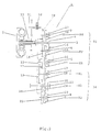
- Fig. 2 is a reversing gear 1 according to the present Invention shown in the case of a torque converter 2 the drive power of a motor on a hollow shaft 3 is transmitted, which represents the drive shaft.
- a fixed gear 4 is arranged on the hollow shaft 3, via which the drive power is passed on.
- the transmission also has countershafts 5, 6, 7, 8 and 9, on which fixed wheels, idler gears and coupling elements, respectively are arranged and with these several countershaft units form.
- the countershaft unit of the forward gear KV consists of the countershaft 6, the idler gear 14, the coupling element 15 and the fixed gear 16.
- the countershaft unit for the first gear K1 by the countershaft 7, the Idler gear 17, the coupling element 18 and the fixed gear 19 are formed.
- the countershaft unit for the second gear K2 has the countershaft 8, the idler gear 20, the clutch unit 21 and the fixed gear 22.
- the counter unit for the third gear K3 from the output shaft 23, the Coupling element 24, the fixed gear 25 and the idler gear 26 are formed.
- the gear unit for the fourth gear exists from the countershaft 9, the idler gear 27, the clutch unit 28 and the fixed gear 29.
- the countershaft unit K4 is preferably located next to the drive shaft 3, which Fixed gear 4 meshes with idler gear 27.
- a torque converter 2 is preferably used driven further hollow shaft 30, the power take-off 31st supplied, which is located far in front of the transmission, so a hydraulic pump required for the vehicle or transmission 32 can be arranged parallel to the transmission can. This creates the necessary installation space for the gearbox further reduced by keeping the axial length to a minimum Measure decreases.
- the countershaft units KV, KR and K4 form a reversing gear unit 33 and the countershaft units K1, K2 and K3 form a gear transmission unit 34, the countershaft units the reverse gear unit 33 on one side in addition to the drive shaft 3 and the countershaft units are provided the gear transmission unit to the countershaft unit Connect KR of reverse gear.
- Fig. 3 is the spatial distribution of the waves of the Reversing gear according to the invention shown schematically.
- the Gear units of the forward gear KV, that of the reverse gear KR and the fourth gear K4 arranged the reverse gear unit 33 form.
- the countershaft unit is KR arranged between the countershaft units KV and K4.
- the other side of the drive shaft 3 remains free.
- the countershaft unit K4 can easily get out of the way with this setup be removed.
- a power take-off 31 On the one opposite the gear units 33 and 34 free side of the drive shaft 3 is a power take-off 31 arranged.
- a second power take-off can be used instead the countershaft unit K4 can be provided, which in the Drawing is not shown.
- the axes of the shafts of the reverse gear unit KV, KR, K4 and the drive shaft 3 form a square 35 and Axes of the shafts of the gear unit K1, K2, K3 and form the shaft of the countershaft unit of reverse gear KR another square 36.
- the individual countershaft units can vehicle to each other be moved, the two quadrilaterals 35 and 36 their Change angle.
- Fig. 3 is a shaft arrangement with a short center distance between the input shaft 3 and the output shaft 23 shown.
- FIG. 4 on the other hand, there is a shaft arrangement with long center distance shown.
- this embodiment of the reversing gear according to the invention is the square 36 opposite the embodiment in Figure 2 drawn out in length. This removes the output shaft 23 and thus the Gear unit of the third gear K3 from the gear unit of reverse gear KR and a larger one is created Wheelbase.
- a reversing gear is shown which for Bridging large distances with an axle transfer gear 37 is provided.
- this shows Transfer case four shafts.
- they are any other types of axle distributor gears can be used.
Landscapes
- Engineering & Computer Science (AREA)
- General Engineering & Computer Science (AREA)
- Mechanical Engineering (AREA)
- Structure Of Transmissions (AREA)
Abstract
Description
- Fig. 1
- eine Darstellung eines Wendegetriebes nach dem Stand der Technik für kurze Achsabstände;
- Fig. 2
- ein Getriebeschema eines Wendegetriebes gemäß der vorliegenden Erfindung;
- Fig. 3
- eine Darstellung der Wellenanordnung eines erfindungsgemäßen Wendegetriebes mit kurzem Achsabstand;
- Fig. 4
- eine Darstellung der Wellenanordnung eines erfindungsgemäßen Wendegetriebes mit langem Achsabstand und
- Fig. 5
- eine schematische Darstellung eines erfindungsgemäßen Wendegetriebes mit Achsverteilergetriebe.
- 1
- Wendegetriebe
- 2
- Drehmomentwandler
- 3
- Antriebswelle
- 4
- Festrad
- 5
- Vorgelegewelle
- 6
- Vorgelegewelle
- 7
- Vorgelegewelle
- 8
- Vorgelegewelle
- 9
- Vorgelegewelle
- 10
- Losrad
- 11
- Kupplungselement
- 12
- Festrad
- 13
- Festrad
- 14
- Losrad
- 15
- Kupplungselement
- 16
- Festrad
- 17
- Losrad
- 18
- Kupplungselement
- 19
- Festrad
- 20
- Losrad
- 21
- Kupplungselement
- 22
- Festrad
- 23
- Abtriebswelle
- 24
- Kupplungselement
- 25
- Festrad
- 26
- Losrad
- 27
- Losrad
- 28
- Kupplungselement
- 29
- Festrad
- 30
- Hohlwelle
- 31
- Nebenantrieb
- 32
- Hydraulikpumpe
- 33
- Wendegetriebeeinheit
- 34
- Ganggetriebeeinheit
- 35
- Viereck
- 36
- Viereck
- 37
- Achsverteilergetriebe
- KV
- Vorgelegeeinheit Vorwärtsgang
- KR
- Vorgelegeeinheit Rückwärtsgang
- K1
- Vorgelegeeinheit erster Gang
- K2
- Vorgelegeeinheit zweiter Gang
- K3
- Vorgelegeeinheit dritter Gang
- K4
- Vorgelegeeinheit vierter Gang
- AN
- Antriebswelle
Claims (9)
- Lastschaltbares, mehrgängiges Wendegetriebe mit einer Antriebswelle, einer Abtriebswelle und mehreren Vorgelegewellen mit auf diesen verteilten Losrädern, Festrädern und Schaltkupplungen, die mehrere Vorgelegeeinheiten (KR, KV, K1, K2, K3, K4) zur Gang- und Richtungsschaltung bilden, dadurch gekennzeichnet, dass die einzelnen Wellen zu einer Wendegetriebeeinheit (33) (KV, KR, K4) und einer Ganggetriebeeinheit (34) (K1, K2, K3) zusammengefasst sind, wobei die Wendegetriebeeinheit an einer beliebigen Seite der Antriebswelle (3) vorgesehen ist und die Ganggetriebeeinheit (34) an die Wendegetriebeeinheit (33) anschließt, sodass die Wendegetriebeeinheit (33) und die Ganggetriebeeinheit (34) bezogen auf die Antriebswelle (3) hintereinander auf einer Seite der Antriebswelle angeordnet sind.
- Wendegetriebe nach Anspruch 1, dadurch gekennzeichnet, dass die Ganggetriebeeinheit (34) an einer beliebigen freien Stelle am Umfang der Vorgelegewelle (5) des Rückwärtsganges (KR) vorgesehen ist.
- Wendegetriebe nach Anspruch 1 oder 2, dadurch gekennzeichnet, dass die Wellen (5, 6, 9) der Wendegetriebeeinheit (33) und die Antriebswelle (3) eine Viereck (35) und die Wellen (7, 8, 23) der Ganggetriebeeinheit (34) und eine Welle der Wendegetriebeeinheit (33) ein weiteres Viereck (36) bilden, wobei die Winkel der Vierecke (35, 36) veränderlich sind.
- Wendegetriebe nach einem der vorhergehenden Ansprüche, dadurch gekennzeichnet, dass an die Abtriebswelle (23) ein Achsverteilergetriebe (37) anschließbar ist.
- Wendegetriebe nach einem der vorhergehenden Ansprüche, dadurch gekennzeichnet, dass die Vorgelegeeinheit des vierten Gangs (K4) unabhängig von den übrigen Vorgelegeeinheiten neben der Antriebswelle (3) angeordnet ist.
- Wendegetriebe nach einem der vorhergehenden Ansprüche, dadurch gekennzeichnet , dass die Vorgelegeeinheit des vierten Gangs (K4) ohne weitere Veränderungen aus dem Wendegetriebe (1) herausnehmbar ist.
- Wendegetriebe nach einem der vorhergehenden Ansprüche, dadurch gekennzeichnet, dass parallel neben der Antriebswelle (3) ein Nebenabtrieb (31) angeordnet ist.
- Wendegetriebe nach einem der vorhergehenden Ansprüche, dadurch gekennzeichnet, dass der Nebenantrieb (31) motorabhängig ist.
- Wendegetriebe nach einem der vorhergehenden Ansprüche, dadurch gekennzeichnet, dass an Stelle der Vorgelegeeinheit des vierten Gangs (K4) ein Nebenabtrieb vorsehbar ist.
Applications Claiming Priority (2)
| Application Number | Priority Date | Filing Date | Title |
|---|---|---|---|
| DE10131329 | 2001-06-28 | ||
| DE10131329A DE10131329A1 (de) | 2001-06-28 | 2001-06-28 | Lastschaltbares Wendegetriebe |
Publications (3)
| Publication Number | Publication Date |
|---|---|
| EP1275879A2 true EP1275879A2 (de) | 2003-01-15 |
| EP1275879A3 EP1275879A3 (de) | 2008-12-10 |
| EP1275879B1 EP1275879B1 (de) | 2010-04-07 |
Family
ID=7689863
Family Applications (1)
| Application Number | Title | Priority Date | Filing Date |
|---|---|---|---|
| EP02014138A Expired - Lifetime EP1275879B1 (de) | 2001-06-28 | 2002-06-25 | Lastschaltbares Wendegetriebe |
Country Status (3)
| Country | Link |
|---|---|
| US (1) | US6752034B2 (de) |
| EP (1) | EP1275879B1 (de) |
| DE (2) | DE10131329A1 (de) |
Cited By (1)
| Publication number | Priority date | Publication date | Assignee | Title |
|---|---|---|---|---|
| WO2016180898A1 (en) * | 2015-05-11 | 2016-11-17 | Dana Belgium N.V. | Transmission for a vehicle and driveline comprising the transmission |
Families Citing this family (17)
| Publication number | Priority date | Publication date | Assignee | Title |
|---|---|---|---|---|
| DE10201590A1 (de) * | 2002-01-17 | 2003-07-31 | Zahnradfabrik Friedrichshafen | Lastschaltgetriebe mit hydrodynamischem und optinalem mechanischen Leistungspfad |
| DE10201837A1 (de) * | 2002-01-18 | 2003-07-31 | Zahnradfabrik Friedrichshafen | Lastschaltgetriebe mit hydrodynamischem und mechanischem Leistungspfad |
| DE10330157A1 (de) * | 2003-07-04 | 2005-02-03 | Zf Friedrichshafen Ag | Lastschaltgetriebe für Baumaschinen, insbesondere für Baggerlader und Telehandler |
| DE10330159A1 (de) * | 2003-07-04 | 2005-02-03 | Zf Friedrichshafen Ag | Lastschaltgetriebe für Baumaschinen, insbesondere für Baggerlader und Telehandler |
| US7044014B2 (en) | 2004-05-25 | 2006-05-16 | Ford Global Technologies, Llc | Dual clutch automatic transaxle |
| US7272986B2 (en) * | 2005-07-15 | 2007-09-25 | Ford Global Technologies, Llc | Dual input automatic transaxle |
| US20060097006A1 (en) * | 2005-10-11 | 2006-05-11 | Erie County Plastics Corporation | Pour spout fitment with internal cut off |
| JP5022810B2 (ja) * | 2007-08-02 | 2012-09-12 | アイシン・エーアイ株式会社 | 6組の前進変速ギヤ対を有する変速機 |
| DE102008002069A1 (de) * | 2008-05-29 | 2009-12-03 | Zf Friedrichshafen Ag | Mehrgängiges Lastschaltgetriebe |
| CN102003502B (zh) * | 2010-12-13 | 2013-01-09 | 四川成都成工工程机械股份有限公司 | 一种适用于工程机械的动力换档变速器 |
| US8522634B2 (en) * | 2011-01-31 | 2013-09-03 | Deere & Company | Powertrain comprising a three speed transmission |
| KR101398560B1 (ko) | 2013-07-02 | 2014-06-27 | 현경열 | 다단 자동 변속기 |
| DE102014219106A1 (de) | 2014-09-23 | 2016-03-24 | Zf Friedrichshafen Ag | Lastschaltbares Wendegetriebe |
| DE102015202679A1 (de) | 2015-02-13 | 2016-08-18 | Zf Friedrichshafen Ag | Lastschaltbares mehrgängiges Wendegetriebe |
| US20170074393A1 (en) * | 2015-09-11 | 2017-03-16 | Nentor Marku | All Clutch Sequential (ACS) |
| DE102016203503A1 (de) | 2016-03-03 | 2017-09-07 | Zf Friedrichshafen Ag | Lastschaltgetriebe für Arbeitsmaschinen |
| US11118535B2 (en) | 2019-03-05 | 2021-09-14 | General Electric Company | Reversing gear assembly for a turbo machine |
Family Cites Families (22)
| Publication number | Priority date | Publication date | Assignee | Title |
|---|---|---|---|---|
| US2887201A (en) | 1953-05-11 | 1959-05-19 | Mack Trucks | Clutching mechanism for front axle drive for automotive vehicles |
| DE1025278B (de) * | 1954-03-08 | 1958-02-27 | Clark Equipment Co | Zahnraederwecselgetriebe, insbesonderer fuer Kraftfahrzeuge |
| DE1178262B (de) | 1960-03-31 | 1964-09-17 | Siemens Reiniger Werke Ag | Ein- und ausrueckbare Wellenkupplung |
| US3350951A (en) * | 1965-12-06 | 1967-11-07 | Clark Equipment Co | Transmission |
| US4063464A (en) * | 1975-10-03 | 1977-12-20 | Caterpillar Tractor Co. | Agricultural tractor transmission |
| US4245519A (en) * | 1977-08-22 | 1981-01-20 | Zahnradfabrik Friedrichshafen Aktiengesellschaft | Multispeed reversible transmission shiftable under load |
| US4392391A (en) * | 1980-11-07 | 1983-07-12 | Cooper Industries, Inc. | Multispeed reversible power shift transmission |
| US4823639A (en) * | 1984-06-04 | 1989-04-25 | Caterpillar Inc. | Countershaft transmission |
| DE3620250A1 (de) * | 1986-06-16 | 1987-12-17 | Claas Ohg | Lastschaltgetriebe fuer fahrzeuge |
| US4771647A (en) * | 1987-10-21 | 1988-09-20 | Caterpillar Inc. | Countershaft transmission |
| DE59008815D1 (de) | 1989-07-14 | 1995-05-04 | Zahnradfabrik Friedrichshafen | Klauenkupplung mit grossem abweiswinkel und kleiner halte- und lösekraft. |
| DE4021653A1 (de) | 1989-07-14 | 1991-01-24 | Zahnradfabrik Friedrichshafen | Klauenkupplung mit grossem abweiswinkel und kleiner halte- und loesekraft |
| DE9203424U1 (de) * | 1992-03-13 | 1992-04-23 | Steyr-Daimler-Puch Ag, Wien | Vielstufiges Lastschaltgetriebe |
| US5249475A (en) * | 1992-08-31 | 1993-10-05 | Deere & Company | Eight- to sixteen-speed powershift transmission |
| DE4242941A1 (de) * | 1992-12-18 | 1994-06-23 | Zahnradfabrik Friedrichshafen | Unter Last schaltbares, mehrgängiges Wendegetriebe |
| US5471892A (en) * | 1994-04-21 | 1995-12-05 | General Motors Corporation | Multi-speed parallel axis three countershafts and an output shaft power transmission |
| DE4416930A1 (de) | 1994-05-13 | 1995-11-16 | Zahnradfabrik Friedrichshafen | Unter Last schaltbares, mehrgängiges Wendegetriebe |
| DE4416929A1 (de) * | 1994-05-13 | 1995-11-16 | Zahnradfabrik Friedrichshafen | Unter Last schaltbares, mehrgängiges Wendegetriebe |
| US5557978A (en) * | 1995-03-07 | 1996-09-24 | Deere & Company | Countershaft power transmission |
| US5608591A (en) * | 1995-06-09 | 1997-03-04 | International Business Machines Corporation | Integrated head-electronics interconnection suspension for a data recording disk drive |
| KR100503612B1 (ko) * | 1998-08-28 | 2006-08-30 | 두산인프라코어 주식회사 | 중장비용 변속기 |
| FR2805221B1 (fr) * | 2000-02-18 | 2002-06-07 | Peugeot Citroen Automobiles Sa | Systeme de transmission de mouvement pour vehicule a propulsion hybride |
-
2001
- 2001-06-28 DE DE10131329A patent/DE10131329A1/de not_active Withdrawn
-
2002
- 2002-06-25 EP EP02014138A patent/EP1275879B1/de not_active Expired - Lifetime
- 2002-06-25 DE DE50214331T patent/DE50214331D1/de not_active Expired - Lifetime
- 2002-06-27 US US10/185,501 patent/US6752034B2/en not_active Expired - Lifetime
Cited By (4)
| Publication number | Priority date | Publication date | Assignee | Title |
|---|---|---|---|---|
| WO2016180898A1 (en) * | 2015-05-11 | 2016-11-17 | Dana Belgium N.V. | Transmission for a vehicle and driveline comprising the transmission |
| CN107743557A (zh) * | 2015-05-11 | 2018-02-27 | 达纳比利时股份有限公司 | 用于车辆的变速器和包括该变速器的传动系统 |
| US10808804B2 (en) | 2015-05-11 | 2020-10-20 | Dana Belgium N.V. | Transmission for a vehicle and driveline comprising the transmission |
| CN107743557B (zh) * | 2015-05-11 | 2022-06-07 | 达纳比利时股份有限公司 | 用于车辆的变速器和包括该变速器的传动系统 |
Also Published As
| Publication number | Publication date |
|---|---|
| US20030015050A1 (en) | 2003-01-23 |
| EP1275879A3 (de) | 2008-12-10 |
| DE10131329A1 (de) | 2003-01-09 |
| DE50214331D1 (de) | 2010-05-20 |
| US6752034B2 (en) | 2004-06-22 |
| EP1275879B1 (de) | 2010-04-07 |
Similar Documents
| Publication | Publication Date | Title |
|---|---|---|
| EP1275879B1 (de) | Lastschaltbares Wendegetriebe | |
| EP1642044B1 (de) | Lastschaltgetriebe für baumaschinen, insbesondere für baggerlader und telehandler | |
| DE3822330C2 (de) | ||
| DE102007058425B4 (de) | Mehrgang-Doppelkupplungsgetriebe | |
| EP1642043B1 (de) | Lastschaltgetriebe für baumaschinen, insbesondere für baggerlader und telehandler | |
| DE4034689C2 (de) | Hydrostatischer Antrieb, vorzugsweise für ein Erdbewegungsfahrzeug, beispielweise Radlader | |
| DE4343402A1 (de) | Stufenloses hydrostatisches Leistungsverzweigungsgetriebe | |
| WO2011151322A1 (de) | Getriebeanordnung | |
| DE2525888A1 (de) | Leistungsverzweigtes getriebe | |
| EP1329648B1 (de) | Lastschaltgetriebe mit hydrodynamischem und optionalem mechanischen Leistungspfad | |
| EP3109509A1 (de) | Getriebeanordnung | |
| EP0474143B1 (de) | Getriebe | |
| EP1740848A1 (de) | Schaltgetriebe in vorgelegewellenbauweise | |
| DE4242942A1 (de) | Unter Last schaltbares, mehrgängiges Wendegetriebe | |
| DE2645957A1 (de) | Zahnraederwechselgetriebe in gruppenbauweise | |
| EP1329647B1 (de) | Lastschaltgetriebe mit hydrodynamischem und mechanischem Leistungspfad | |
| DE2656474C3 (de) | Hydraulische Kriechgang-Antriebsanordnung für ein Nutzfahrzeug | |
| DE102013202386A1 (de) | Lastschaltgetriebe für Baumaschinen, beispielsweise für Baggerlader oder Telehandler | |
| DE10259424A1 (de) | Lastschaltbares mehrgängiges Wendegetriebe | |
| WO2001071214A1 (de) | Unter last schaltbares, mehrgängiges wendegetriebe | |
| DE102015205409A1 (de) | Getriebeanordnung | |
| DE10248826A1 (de) | Unter Last schaltbares mehrgängiges Wendegetriebe | |
| WO2023046594A1 (de) | Zapfwellengetriebe | |
| DE102020200509A1 (de) | Leistungsverzweigungsgetriebe, Getriebemodul und Fahrzeug | |
| DE2132669A1 (de) | Zahnradwechselgetriebe in gruppenbauart |
Legal Events
| Date | Code | Title | Description |
|---|---|---|---|
| PUAI | Public reference made under article 153(3) epc to a published international application that has entered the european phase |
Free format text: ORIGINAL CODE: 0009012 |
|
| AK | Designated contracting states |
Kind code of ref document: A2 Designated state(s): AT BE CH CY DE DK ES FI FR GB GR IE IT LI LU MC NL PT SE TR |
|
| AX | Request for extension of the european patent |
Free format text: AL;LT;LV;MK;RO;SI |
|
| PUAL | Search report despatched |
Free format text: ORIGINAL CODE: 0009013 |
|
| AK | Designated contracting states |
Kind code of ref document: A3 Designated state(s): AT BE CH CY DE DK ES FI FR GB GR IE IT LI LU MC NL PT SE TR |
|
| AX | Request for extension of the european patent |
Extension state: AL LT LV MK RO SI |
|
| RIC1 | Information provided on ipc code assigned before grant |
Ipc: F16H 3/093 20060101AFI20081106BHEP Ipc: F16H 47/06 20060101ALI20081106BHEP |
|
| 17P | Request for examination filed |
Effective date: 20081121 |
|
| 17Q | First examination report despatched |
Effective date: 20090605 |
|
| AKX | Designation fees paid |
Designated state(s): BE DE FR GB IT |
|
| GRAP | Despatch of communication of intention to grant a patent |
Free format text: ORIGINAL CODE: EPIDOSNIGR1 |
|
| GRAS | Grant fee paid |
Free format text: ORIGINAL CODE: EPIDOSNIGR3 |
|
| GRAA | (expected) grant |
Free format text: ORIGINAL CODE: 0009210 |
|
| AK | Designated contracting states |
Kind code of ref document: B1 Designated state(s): BE DE FR GB IT |
|
| REG | Reference to a national code |
Ref country code: GB Ref legal event code: FG4D Free format text: NOT ENGLISH |
|
| REF | Corresponds to: |
Ref document number: 50214331 Country of ref document: DE Date of ref document: 20100520 Kind code of ref document: P |
|
| BERE | Be: lapsed |
Owner name: ZF FRIEDRICHSHAFEN A.G. Effective date: 20100630 |
|
| PLBE | No opposition filed within time limit |
Free format text: ORIGINAL CODE: 0009261 |
|
| STAA | Information on the status of an ep patent application or granted ep patent |
Free format text: STATUS: NO OPPOSITION FILED WITHIN TIME LIMIT |
|
| 26N | No opposition filed |
Effective date: 20110110 |
|
| REG | Reference to a national code |
Ref country code: FR Ref legal event code: ST Effective date: 20110228 |
|
| PG25 | Lapsed in a contracting state [announced via postgrant information from national office to epo] |
Ref country code: FR Free format text: LAPSE BECAUSE OF NON-PAYMENT OF DUE FEES Effective date: 20100630 |
|
| PG25 | Lapsed in a contracting state [announced via postgrant information from national office to epo] |
Ref country code: BE Free format text: LAPSE BECAUSE OF NON-PAYMENT OF DUE FEES Effective date: 20100630 |
|
| PGFP | Annual fee paid to national office [announced via postgrant information from national office to epo] |
Ref country code: GB Payment date: 20160622 Year of fee payment: 15 |
|
| GBPC | Gb: european patent ceased through non-payment of renewal fee |
Effective date: 20170625 |
|
| PG25 | Lapsed in a contracting state [announced via postgrant information from national office to epo] |
Ref country code: GB Free format text: LAPSE BECAUSE OF NON-PAYMENT OF DUE FEES Effective date: 20170625 |
|
| PGFP | Annual fee paid to national office [announced via postgrant information from national office to epo] |
Ref country code: IT Payment date: 20190620 Year of fee payment: 18 |
|
| PGFP | Annual fee paid to national office [announced via postgrant information from national office to epo] |
Ref country code: DE Payment date: 20210602 Year of fee payment: 20 |
|
| PG25 | Lapsed in a contracting state [announced via postgrant information from national office to epo] |
Ref country code: IT Free format text: LAPSE BECAUSE OF NON-PAYMENT OF DUE FEES Effective date: 20200625 |
|
| REG | Reference to a national code |
Ref country code: DE Ref legal event code: R071 Ref document number: 50214331 Country of ref document: DE |