EP1275829A1 - Einrichtung zum Einstellen der Temperatur von Abgasen - Google Patents
Einrichtung zum Einstellen der Temperatur von Abgasen Download PDFInfo
- Publication number
- EP1275829A1 EP1275829A1 EP02011697A EP02011697A EP1275829A1 EP 1275829 A1 EP1275829 A1 EP 1275829A1 EP 02011697 A EP02011697 A EP 02011697A EP 02011697 A EP02011697 A EP 02011697A EP 1275829 A1 EP1275829 A1 EP 1275829A1
- Authority
- EP
- European Patent Office
- Prior art keywords
- air gap
- air
- outer shell
- volume
- exhaust gas
- Prior art date
- Legal status (The legal status is an assumption and is not a legal conclusion. Google has not performed a legal analysis and makes no representation as to the accuracy of the status listed.)
- Ceased
Links
Images
Classifications
-
- F—MECHANICAL ENGINEERING; LIGHTING; HEATING; WEAPONS; BLASTING
- F01—MACHINES OR ENGINES IN GENERAL; ENGINE PLANTS IN GENERAL; STEAM ENGINES
- F01N—GAS-FLOW SILENCERS OR EXHAUST APPARATUS FOR MACHINES OR ENGINES IN GENERAL; GAS-FLOW SILENCERS OR EXHAUST APPARATUS FOR INTERNAL-COMBUSTION ENGINES
- F01N3/00—Exhaust or silencing apparatus having means for purifying, rendering innocuous, or otherwise treating exhaust
- F01N3/08—Exhaust or silencing apparatus having means for purifying, rendering innocuous, or otherwise treating exhaust for rendering innocuous
- F01N3/10—Exhaust or silencing apparatus having means for purifying, rendering innocuous, or otherwise treating exhaust for rendering innocuous by thermal or catalytic conversion of noxious components of exhaust
- F01N3/18—Exhaust or silencing apparatus having means for purifying, rendering innocuous, or otherwise treating exhaust for rendering innocuous by thermal or catalytic conversion of noxious components of exhaust characterised by methods of operation; Control
- F01N3/20—Exhaust or silencing apparatus having means for purifying, rendering innocuous, or otherwise treating exhaust for rendering innocuous by thermal or catalytic conversion of noxious components of exhaust characterised by methods of operation; Control specially adapted for catalytic conversion
- F01N3/2006—Periodically heating or cooling catalytic reactors, e.g. at cold starting or overheating
- F01N3/2046—Periodically cooling catalytic reactors
-
- F—MECHANICAL ENGINEERING; LIGHTING; HEATING; WEAPONS; BLASTING
- F01—MACHINES OR ENGINES IN GENERAL; ENGINE PLANTS IN GENERAL; STEAM ENGINES
- F01N—GAS-FLOW SILENCERS OR EXHAUST APPARATUS FOR MACHINES OR ENGINES IN GENERAL; GAS-FLOW SILENCERS OR EXHAUST APPARATUS FOR INTERNAL-COMBUSTION ENGINES
- F01N13/00—Exhaust or silencing apparatus characterised by constructional features
- F01N13/14—Exhaust or silencing apparatus characterised by constructional features having thermal insulation
-
- F—MECHANICAL ENGINEERING; LIGHTING; HEATING; WEAPONS; BLASTING
- F01—MACHINES OR ENGINES IN GENERAL; ENGINE PLANTS IN GENERAL; STEAM ENGINES
- F01N—GAS-FLOW SILENCERS OR EXHAUST APPARATUS FOR MACHINES OR ENGINES IN GENERAL; GAS-FLOW SILENCERS OR EXHAUST APPARATUS FOR INTERNAL-COMBUSTION ENGINES
- F01N3/00—Exhaust or silencing apparatus having means for purifying, rendering innocuous, or otherwise treating exhaust
- F01N3/02—Exhaust or silencing apparatus having means for purifying, rendering innocuous, or otherwise treating exhaust for cooling, or for removing solid constituents of, exhaust
- F01N3/05—Exhaust or silencing apparatus having means for purifying, rendering innocuous, or otherwise treating exhaust for cooling, or for removing solid constituents of, exhaust by means of air, e.g. by mixing exhaust with air
-
- F—MECHANICAL ENGINEERING; LIGHTING; HEATING; WEAPONS; BLASTING
- F01—MACHINES OR ENGINES IN GENERAL; ENGINE PLANTS IN GENERAL; STEAM ENGINES
- F01N—GAS-FLOW SILENCERS OR EXHAUST APPARATUS FOR MACHINES OR ENGINES IN GENERAL; GAS-FLOW SILENCERS OR EXHAUST APPARATUS FOR INTERNAL-COMBUSTION ENGINES
- F01N3/00—Exhaust or silencing apparatus having means for purifying, rendering innocuous, or otherwise treating exhaust
- F01N3/08—Exhaust or silencing apparatus having means for purifying, rendering innocuous, or otherwise treating exhaust for rendering innocuous
- F01N3/0807—Exhaust or silencing apparatus having means for purifying, rendering innocuous, or otherwise treating exhaust for rendering innocuous by using absorbents or adsorbents
- F01N3/0814—Exhaust or silencing apparatus having means for purifying, rendering innocuous, or otherwise treating exhaust for rendering innocuous by using absorbents or adsorbents combined with catalytic converters, e.g. NOx absorption/storage reduction catalysts
-
- F—MECHANICAL ENGINEERING; LIGHTING; HEATING; WEAPONS; BLASTING
- F01—MACHINES OR ENGINES IN GENERAL; ENGINE PLANTS IN GENERAL; STEAM ENGINES
- F01N—GAS-FLOW SILENCERS OR EXHAUST APPARATUS FOR MACHINES OR ENGINES IN GENERAL; GAS-FLOW SILENCERS OR EXHAUST APPARATUS FOR INTERNAL-COMBUSTION ENGINES
- F01N3/00—Exhaust or silencing apparatus having means for purifying, rendering innocuous, or otherwise treating exhaust
- F01N3/08—Exhaust or silencing apparatus having means for purifying, rendering innocuous, or otherwise treating exhaust for rendering innocuous
- F01N3/0807—Exhaust or silencing apparatus having means for purifying, rendering innocuous, or otherwise treating exhaust for rendering innocuous by using absorbents or adsorbents
- F01N3/0871—Exhaust or silencing apparatus having means for purifying, rendering innocuous, or otherwise treating exhaust for rendering innocuous by using absorbents or adsorbents using means for controlling, e.g. purging, the absorbents or adsorbents
-
- F—MECHANICAL ENGINEERING; LIGHTING; HEATING; WEAPONS; BLASTING
- F01—MACHINES OR ENGINES IN GENERAL; ENGINE PLANTS IN GENERAL; STEAM ENGINES
- F01N—GAS-FLOW SILENCERS OR EXHAUST APPARATUS FOR MACHINES OR ENGINES IN GENERAL; GAS-FLOW SILENCERS OR EXHAUST APPARATUS FOR INTERNAL-COMBUSTION ENGINES
- F01N3/00—Exhaust or silencing apparatus having means for purifying, rendering innocuous, or otherwise treating exhaust
- F01N3/08—Exhaust or silencing apparatus having means for purifying, rendering innocuous, or otherwise treating exhaust for rendering innocuous
- F01N3/10—Exhaust or silencing apparatus having means for purifying, rendering innocuous, or otherwise treating exhaust for rendering innocuous by thermal or catalytic conversion of noxious components of exhaust
- F01N3/18—Exhaust or silencing apparatus having means for purifying, rendering innocuous, or otherwise treating exhaust for rendering innocuous by thermal or catalytic conversion of noxious components of exhaust characterised by methods of operation; Control
- F01N3/20—Exhaust or silencing apparatus having means for purifying, rendering innocuous, or otherwise treating exhaust for rendering innocuous by thermal or catalytic conversion of noxious components of exhaust characterised by methods of operation; Control specially adapted for catalytic conversion
- F01N3/2006—Periodically heating or cooling catalytic reactors, e.g. at cold starting or overheating
-
- F—MECHANICAL ENGINEERING; LIGHTING; HEATING; WEAPONS; BLASTING
- F01—MACHINES OR ENGINES IN GENERAL; ENGINE PLANTS IN GENERAL; STEAM ENGINES
- F01N—GAS-FLOW SILENCERS OR EXHAUST APPARATUS FOR MACHINES OR ENGINES IN GENERAL; GAS-FLOW SILENCERS OR EXHAUST APPARATUS FOR INTERNAL-COMBUSTION ENGINES
- F01N2240/00—Combination or association of two or more different exhaust treating devices, or of at least one such device with an auxiliary device, not covered by indexing codes F01N2230/00 or F01N2250/00, one of the devices being
- F01N2240/02—Combination or association of two or more different exhaust treating devices, or of at least one such device with an auxiliary device, not covered by indexing codes F01N2230/00 or F01N2250/00, one of the devices being a heat exchanger
-
- F—MECHANICAL ENGINEERING; LIGHTING; HEATING; WEAPONS; BLASTING
- F01—MACHINES OR ENGINES IN GENERAL; ENGINE PLANTS IN GENERAL; STEAM ENGINES
- F01N—GAS-FLOW SILENCERS OR EXHAUST APPARATUS FOR MACHINES OR ENGINES IN GENERAL; GAS-FLOW SILENCERS OR EXHAUST APPARATUS FOR INTERNAL-COMBUSTION ENGINES
- F01N2260/00—Exhaust treating devices having provisions not otherwise provided for
- F01N2260/10—Exhaust treating devices having provisions not otherwise provided for for avoiding stress caused by expansions or contractions due to temperature variations
-
- Y—GENERAL TAGGING OF NEW TECHNOLOGICAL DEVELOPMENTS; GENERAL TAGGING OF CROSS-SECTIONAL TECHNOLOGIES SPANNING OVER SEVERAL SECTIONS OF THE IPC; TECHNICAL SUBJECTS COVERED BY FORMER USPC CROSS-REFERENCE ART COLLECTIONS [XRACs] AND DIGESTS
- Y02—TECHNOLOGIES OR APPLICATIONS FOR MITIGATION OR ADAPTATION AGAINST CLIMATE CHANGE
- Y02T—CLIMATE CHANGE MITIGATION TECHNOLOGIES RELATED TO TRANSPORTATION
- Y02T10/00—Road transport of goods or passengers
- Y02T10/10—Internal combustion engine [ICE] based vehicles
- Y02T10/12—Improving ICE efficiencies
Definitions
- the invention relates to a device for adjusting the temperature of in an exhaust pipe provided with an outer shell, wherein An air gap is formed between the tube and the outer shell.
- DE 43 10 926 A1 discloses a device and a Process for reducing pollutants in the exhaust gas, increasing the Catalyst temperature by supplying hot exhaust gases, a Lowering the catalytic converter temperature with a cooling fins provided air / air heat exchanger is reached.
- the said Publication is exemplary of a multitude of often very complicated and complex devices and methods for regulating the Exhaust gas temperature.
- the object of the invention is a device for adjusting the To create the temperature of exhaust gases with a simple means Adjustment of the exhaust gas temperature allowed and therefore inexpensive is to be manufactured and assembled, and is error-free and maintenance-free Operation enables.
- the object of the invention is achieved with the features of Claim 1, wherein the underlying idea is the use of an intermediate an exhaust pipe and an outer shell Air gap for insulation on the one hand and for supplying or removing heat on the other hand includes.
- the air gap formed between the inner and outer shell forms a closed volume, which can be filled via an air inlet duct is.
- the air gap expediently also has one Air outlet area, with air inlet and / or air outlet lockable are.
- the volume can be ventilated passively, for example by opening it by control flaps or actively by means of a fan.
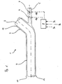
- a double pipe 1 for exhaust gas temperature control is shown.
- the exhaust pipe inner tube 2 is surrounded by an outer shell 3, whereby the air gap 4 is formed.
- the outer tube 3 is at an end region 12 tightly connected to the inner tube, the connection is expediently designed to be displaceable and / or elastic to compensate for temperature-related differences in the expansion.
- the Air gap 4 is provided at one end with an air inlet connection 5 at another end it has air outlets 11. Both the air intake as The air outlet also takes place, for example, via a flanged one Supply or outlet pipe, but it is also very useful if for the air inlet or outlet several inlet or Outlet openings are provided.
- the entry and exit openings are advantageously round, but it can also be useful to be slit-shaped.
- An embodiment is sought in which when flowing through the air gap 4 from the air inlet 5 to the air outlet 11 towards the best possible heat transfer from the inner tube 2 to flowing medium can take place.
- the air volume formed in the air gap 4 is lockable; for this is the Air inlet 5 and possibly also the air outlet 11, for example how shown in the figure, by means of a throttle valve 6 in the air inlet pipe, which is pivotable about an axis, lockable.
- a throttle valve 6 in the air inlet pipe which is pivotable about an axis, lockable.
- a swivel flap Flat slide valve or a rotary slide valve for use.
- Denox catalytic converters used for exhaust gas aftertreatment are used for nitrogen oxide reduction, especially in direct injection lean-burn gasoline engines and diesel engines.
- Denox catalysts used have an absorber catalytic converter that is able to temporarily store NO x during stoichiometric engine operation and to implement it again in shorter sub-stoichiometric operating phases.
- alkali and alkaline earth metals such as barium are used as storage material.
- a prerequisite for functionality is operation in specified temperature ranges.
- the exhaust gas temperature when entering the denox catalyst should be in the range between 250 ° C. and 550 ° C., in particular between 280 ° C. and 500 ° C.
- the air inlet 5 and possibly the air outlet 11 are closed, so that the volume in the air gap 4 is closed.
- the air layer lying between the inner tube 2 and the outer shell 3 acts as an insulator, so that little exhaust gas heat is lost on the way to the catalytic converter.
- the temperature operating range of the Denox catalyst is up currently limited to a maximum of 750 ° to 800 ° Celsius. In the higher load range of the engine it is therefore necessary that exhaust gas on the way to Cool catalyst.
- air is supplied in a first step and air outlet opened by, for example, the throttle valve 6 in Opening direction is pivoted, the drive expediently by means of an actuator such as an electric motor.
- the flap (6) is adjustable under pressure difference control, in this case it is a not directly controlled actuator.
- the air gap 4 between the inner tube 2 and the outer shell 3 can be from Air is flowed through, for example using the airstream. In this way, the air flowing through the inner tube 2 dissipated heat removed. This state corresponds to one passive ventilation of the air gap 4, the degree of opening in the Air inlet or throttle valve 6 located in the air outlet Flow through the air gap 4 determined.
- the state of the pleasure gap volume can be changed continuously, by slowly opening the throttle valve 6 and then when it has a has reached the fully open position, possibly already earlier, the fan 7 is switched on, the one of the control corresponding changeable air volume penetrates.
- Electric motor motor operated throttle valve 6, the fan 7 and if necessary, further elements influencing ventilation, for example in Air outlet 11 takes place by means of a control device 8.
- a control device 8 For control a plurality of input variables are used in the figure designated by way of example with 9a, 9b, 9c, these being signals from Temperature sensors, lambda sensors, the load of the engine characterizing parameters, vehicle speed, etc.
- the signals can come directly from sensors or from one Bus system can be tapped.
- a regulation takes place in such a way that the exhaust gas flowing through the inner tube 2 is tempered in such a way that it within the thermal range applicable to the operation of the catalyst Limits.
- the flow through the air gap 4 takes place in the embodiment in the same direction in which exhaust gas flows through the inner tube 2, in another embodiment it is useful if the Air gap 4 is flowed through against the exhaust gas flow direction.
Landscapes
- Engineering & Computer Science (AREA)
- Chemical & Material Sciences (AREA)
- Combustion & Propulsion (AREA)
- Mechanical Engineering (AREA)
- General Engineering & Computer Science (AREA)
- Chemical Kinetics & Catalysis (AREA)
- Health & Medical Sciences (AREA)
- Toxicology (AREA)
- Exhaust Gas After Treatment (AREA)
Abstract
Die Temperatur von in einem Abgasrohr (2) strömenden Abgasen wird geregelt, indem ein zwischen dem Abgasrohr (2) und einer dieses umgebenden Außenschale (3) befindlicher Luftspalt (4) zur Isolation abschließbar und Kühlung passiv und/oder aktiv belüftbar ist.
Description
Die Erfindung betrifft eine Einrichtung zum Einstellen der Temperatur von in
einem mit einer Außenschale versehenen Rohr geführten Abgasen, wobei
zwischen Rohr und Außenschale ein Luftspalt gebildet wird.
Um die Schadstoffemission von Kraftfahrzeugen zu verringern, ist eine
Abgasnachbehandlung mittels Katalysatoren notwendig; insbesondere zur
Stickoxidreduktion kommen dabei sogenannte Denoxkatalysatoren zur
Anwendung. Für den Ablauf der Reaktionen im Katalysator ist es einerseits
vorteilhaft, wenn die Abgastemperatur beim Eintritt in den Katalysator in etwa
im Bereich zwischen 250°C und 550°C, insbesondere zwischen 280°C und
500°C liegt, andererseits hat sich als Schwierigkeit herausgestellt, dass die
thermische Beständigkeit üblicher Denoxkatalysatoren gering ist, weshalb
die Abgastemperatur derzeit 750° bis 800° Celsius nicht übersteigen darf.
Es besteht also einerseits die Notwendigkeit, beispielsweise während der
Kaltstartphase oder im Schwachlastbetrieb, den Katalysator schnell
aufzuheizen bzw. nicht zu stark abkühlen zu lassen, andererseits ist im
Volllastbereich eine Kühlung der Abgase vor Eintritt in den Katalysator
notwendig.
Verschiedene Vorrichtungen und Verfahren zur Einstellung der Temperatur
eines Katalysators sind im Stand der Technik bekannt geworden. So
offenbart beispielsweise die DE 43 10 926 A1 eine Vorrichtung und ein
Verfahren zur Schadstoffminderung im Abgas, wobei eine Erhöhung der
Katalysatortemperatur durch Zuleitung von heißen Abgasen, eine
Absenkung der Katalysatortemperatur durch einen mit Kühlrippen
versehenen Luft-/Luftwärmetauscher erreicht wird. Die genannte
Veröffentlichung steht beispielhaft für eine Vielzahl oft sehr komplizierter und
aufwendiger Vorrichtungen und Verfahren zur Regelung der
Abgastemperatur.
Aufgabe der Erfindung ist es, eine Einrichtung zum Einstellen der
Temperatur von Abgasen zu schaffen, die mit einfachen Mitteln eine
Einstellung der Abgastemperatur gestattet und somit kostengünstig
herzustellen und zu montieren ist sowie einen fehler- und wartungsfreien
Betrieb ermöglicht.
Die erfindungsgemäße Lösung der Aufgabe erfolgt mit den Merkmalen des
Anspruches 1, wobei die zugrundeliegende Idee die Nutzung eines zwischen
einem abgasführenden Innenrohr und einer Außenschale gebildeten
Luftspaltes zur Isolierung einerseits und zur Wärmezu- oder -abfuhr
andererseits beinhaltet.
Vorteilhafte Ausgestaltungen der erfindungsgemäßen Einrichtung sind in den
Unteransprüchen beschrieben.
Der zwischen Innen- und Außenschale gebildete Luftspalt bildet ein
abgeschlossenes Volumen, welches über einen Lufteintrittskanal befüllbar
ist. Zweckmäßigerweise weist der Luftspalt weiterhin einen
Luftaustrittsbereich auf, wobei Lufteintritt- und/ oder Luftaustritt abschließbar
sind. Eine Belüftung des Volumens kann passiv beispielsweise durch Öffnen
von Regelklappen oder aktiv mittels eines Lüfters erfolgen.
Nachfolgend wird ein bevorzugtes Ausführungsbeispiel der Erfindung unter
Bezugnahme auf die Figur näher erläutert. Dabei zeigt schematisch und
beispielhaft:
- Figur 1
- ein Doppelrohr zur Abgastemperierung.
In Figur 1 ist ein Doppelrohr 1 zur Abgastemperierung dargestellt. Das
abgasführende Innenrohr 2 ist von einer Außenschale 3 umgeben, wodurch
der Luftspalt 4 gebildet wird. Das Außenrohr 3 ist an einem Endbereich 12
dicht mit dem Innenrohr verbunden, wobei die Verbindung
zweckmäßigerweise verschieblich und/oder elastisch ausgestaltet ist, um
temperaturbedingte Differenzen in der Ausdehnung auszugleichen. Der
Luftspalt 4 ist an einem Ende mit einem Lufteintrittsstutzen 5 versehen, an
einem anderen Ende weist er Luftaustritte 11 auf. Sowohl der Lufteintritt als
auch der Luftaustritt erfolgt beispielsweise über ein angeflanschtes
Zuführungs- bzw. Austrittsrohr, jedoch ist es auch sehr zweckmäßig, wenn
zum Luftein- bzw. austritt mehrere über den Umfang verteilte Einlass- bzw.
Auslassöffnungen vorgesehen sind. Die Ein- bzw. Austrittsöffnungen sind
vorteilhaft rund ausgebildet, jedoch kann es auch zweckmäßig sein diese
schlitzförmig auszubilden. Angestrebt wird eine Ausgestaltung, bei welcher
beim Durchströmen des Luftspaltes 4 vom Lufteintritt 5 zum Luftaustritt 11
hin ein bestmöglicher Wärmeübergang vom Innenrohr 2 zum
durchströmenden Medium hin erfolgen kann.
Das im Luftspalt 4 gebildete Luftvolumen ist abschließbar; hierzu ist der
Lufteintritt 5 und gegebenenfalls auch der Luftaustritt 11, beispielsweise wie
in der Figur dargestellt, mittels einer Drosselklappe 6 im Lufteintrittsrohr,
welche um eine Achse verschwenkbar ist, abschließbar. In einem anderen
Ausführungsbeispiel kommt zweckmäßigerweise eine Schwenkklappe, ein
Flachschieber oder ein Drehschieber zur Anwendung.
Zur Abgasnachbehandlung eingesetzte Denoxkatalysatoren werden zur
Stickoxidreduktion insbesondere bei direkt einspritzenden mager
betriebenen Ottomotoren sowie Dieselmotoren eingesetzt. Verwendete
Denoxkatalysatoren verfügen über einen Absorber-Katalysator, der in der
Lage ist, bei überstöchiometrischem Motorbetrieb NOx zwischenzuspeichern
und dieses in kürzeren unterstöchiometrischen Betriebsphasen wieder
umzusetzen. Insbesondere finden als Speichermaterial Alkali- und
Erdalkalimetalle wie Barium Verwendung. Vorraussetzung für die
Funktionsfähigkeit ist jedoch ein Betrieb in vorgegebenen
Temperaturbereichen. Im Ausführungsbeispiel soll die Abgastemperatur
beim Eintritt in den Denoxkatalysator im Bereich zwischen 250°C und 550°C,
insbesondere zwischen 280°C und 500°C, liegen. Um diese
Abgastemperatur, beispielsweise während einer Kaltstartphase, schnell zu
erreichen, bzw. im Schwachlastbetrieb nicht zu unterschreiten, werden
Lufteinlass 5 und gegebenenfalls der Luftauslass 11 verschlossen, so dass
das Volumen im Luftspalt 4 abgeschlossen ist. Die zwischen Innenrohr 2 und
Außenschale 3 liegende Luftschicht wirkt als Isolator, so dass wenig
Abgaswärme auf dem Weg zum Katalysator verloren geht.
Der temperaturmäßige Betriebsbereich des Denoxkatalysators ist nach oben
auf zur Zeit maximal 750° bis 800° Celsius begrenzt. Im höheren Lastbereich
des Motors ist es deshalb notwendig, dass Abgas auf dem Weg zum
Katalysator zu kühlen. Hierzu werden in einem ersten Schritt Luftzuführung
und Luftaustritt geöffnet, indem beispielsweise die Drosselklappe 6 in
Öffnungsrichtung verschwenkt wird, wobei der Antrieb zweckmäßigerweise
mittels eines Stellgliedes wie Elektromotor erfolgt. In einem anderen
Ausführungsbeispiel ist die Klappe (6) druckdifferenzgesteuert verstellbar,
wobei es sich in diesem Fall um ein nicht direkt geregeltes Stellglied handelt.
Der zwischen Innenrohr 2 und Außenschale 3 liegende Luftspalt 4 kann von
Luft durchströmt werden, wobei beispielsweise der Fahrtwind genutzt wird.
Auf diese Weise wird die von Innenrohr 2 an die durchströmende Luft
abgegebene Wärme abtransportiert. Dieser Zustand entspricht einer
passiven Belüftung des Luftspaltes 4, wobei der Öffnungsgrad der im
Lufteinlass respektive im Luftauslass befindlichen Drosselklappe 6 die
Durchströmung des Luftspaltes 4 bestimmt.
In einem zweiten Schritt wird beispielsweise bei einem Betrieb im
Volllastbereich, wenn die Drosselklappe 6 bereits vollständig geöffnet ist, ein
Lüfter 7 hinzugeschaltet. Auf diese Weise wird der Luftdurchsatz in Luftspalt
4 noch weiter gesteigert, wobei das durchgesetzte Luftvolumen mittels des
Lüfters 7 regelbar ist. Dieser Zustand entspricht einer aktiven Belüftung des
Luftspaltes 4.
Zwischen abgeschlossenem, passiv belüftetem und/oder aktiv belüftetem
Zustand des Lustspaltvolumens kann kontinuierlich gewechselt werden,
indem die Drosselklappe 6 langsam geöffnet wird und dann, wenn sie eine
vollständig geöffnete Stellung erreicht hat, gegebenenfalls bereits auch
schon früher, der Lüfter 7 zugeschaltet wird, der ein der Ansteuerung
entsprechendes veränderbares Luftvolumen durchsetzt.
Die Ansteuerung der mittels eines in der Figur nicht dargestellten
Elektromotormotors betätigten Drosselklappe 6, des Lüfters 7 sowie
gegebenenfalls weiterer die Belüftung beeinflussender Elemente etwa im
Luftauslass 11, erfolgt mittels einer Regeleinrichtung 8. Zur Regelung
werden eine Mehrzahl von Eingangsgrößen verwendet, in der Figur
beispielhaft mit 9a, 9b, 9c bezeichnet, wobei es sich um Signale von
Temperatursensoren, Lambdasonden, die Last des Motors
charakterisierenden Parametern, der Fahrzeuggeschwindigkeit etc. handelt.
Die Signale können direkt von Sensoren stammen oder auch von einem
Bussystem abgegriffen werden. Eine Regelung erfolgt dahingehend, dass
das durch das Innenrohr 2 strömende Abgas jeweils so temperiert wird, das
es innerhalb der für den Betrieb des Katalysators geltenden thermischen
Grenzen liegt.
Die Durchströmung des Luftspaltes 4 erfolgt im Ausführungsbeispiel in der
selben Richtung, in der auch das Innenrohr 2 vom Abgas durchströmt wird,
wobei es in einem anderen Ausführungsbeispiel zweckmäßig ist, wenn der
Luftspalt 4 entgegen der Abgasströmungsrichtung durchströmt wird.
Claims (8)
- Einrichtung zum Einstellen der Temperatur von in einem mit einer Außenschale versehenen Rohr geführten Abgasen, wobei zwischen Rohr und Außenschale ein Luftspalt gebildet wird, dadurch gekennzeichnet, dass der Luftspalt (4) einerseits zumindest zeitweise isolierend und andererseits zumindest zeitweise Wärme zu- oder abführend nutzbar ist.
- Einrichtung nach Anspruch 1, dadurch gekennzeichnet, dass das Luftspaltvolumen (4) abschließbar ist.
- Einrichtung nach Anspruch 1, dadurch gekennzeichnet, dass das Luftspaltvolumen (4) passiv belüftbar ist.
- Einrichtung nach Anspruch 2 oder 3, bei der das Luftspaltvolumen einen Eintritts- sowie einen Austrittsbereich aufweist, dadurch gekennzeichnet, dass im Eintritts- (5) und/oder im Austrittsbereich (11) wenigstens eine Einrichtungen (6) zur Drosselung des Durchflusses angeordnet ist.
- Einrichtung nach Anspruch 1, dadurch gekennzeichnet, dass das Luftspaltvolumen (4) aktiv belüftbar ist.
- Einrichtung nach Anspruch 5 bei der das Luftspaltvolumen einen Eintritts- sowie einen Austrittsbereich aufweist, dadurch gekennzeichnet, dass im Eintritts- (5) und/oder im Austrittsbereich (11) wenigstens ein Lüfter (7) angeordnet ist.
- Einrichtung nach wenigstens einem der vorhergegangenen Ansprüche, dadurch gekennzeichnet, dass ein Wechsel zwischen abgeschlossenem, passiv belüftetem und/oder aktiv belüftetem Zustand des Luftspaltvolumens (4) abhängig von einer Abgassolltemperatur erfolgt.
- Einrichtung nach Anspruch 7, dadurch gekennzeichnet, dass ein Wechsel mittels einer Regeleinrichtung (8) durch entsprechende Ansteuerung der wenigstens einen Einrichtung (6) zur Drosselung des Durchflusses und/oder des wenigstens einen Lüfters (7) geregelt wird.
Applications Claiming Priority (2)
| Application Number | Priority Date | Filing Date | Title |
|---|---|---|---|
| DE10133422A DE10133422A1 (de) | 2001-07-10 | 2001-07-10 | Einrichtung zum Einstellen der Temperatur von Abgasen |
| DE10133422 | 2001-07-10 |
Publications (1)
| Publication Number | Publication Date |
|---|---|
| EP1275829A1 true EP1275829A1 (de) | 2003-01-15 |
Family
ID=7691241
Family Applications (1)
| Application Number | Title | Priority Date | Filing Date |
|---|---|---|---|
| EP02011697A Ceased EP1275829A1 (de) | 2001-07-10 | 2002-06-04 | Einrichtung zum Einstellen der Temperatur von Abgasen |
Country Status (2)
| Country | Link |
|---|---|
| EP (1) | EP1275829A1 (de) |
| DE (1) | DE10133422A1 (de) |
Cited By (1)
| Publication number | Priority date | Publication date | Assignee | Title |
|---|---|---|---|---|
| WO2004090297A3 (de) * | 2003-04-10 | 2004-12-23 | Avl List Gmbh | Brennkraftmaschine mit abgasnachbehandlungseinrichtung im abgasstrang |
Families Citing this family (7)
| Publication number | Priority date | Publication date | Assignee | Title |
|---|---|---|---|---|
| AT501385B1 (de) * | 2003-04-10 | 2007-12-15 | Avl List Gmbh | Brennkraftmaschine mit einem abgassystem |
| DE102007006029A1 (de) * | 2007-02-07 | 2008-08-14 | Dr. Ing. H.C. F. Porsche Aktiengesellschaft | Kraftfahrzeug |
| DE102008014437A1 (de) | 2008-03-14 | 2009-03-12 | Daimler Ag | Abgasstrang |
| DE102008014435A1 (de) | 2008-03-14 | 2009-03-12 | Daimler Ag | Abgasstrang |
| JP6319009B2 (ja) | 2014-09-19 | 2018-05-09 | 株式会社デンソー | 冷却装置 |
| DE102018200311A1 (de) * | 2018-01-10 | 2019-07-11 | Bayerische Motoren Werke Aktiengesellschaft | Motorradabgaskrümmer |
| DE102018200662B4 (de) * | 2018-01-16 | 2025-05-28 | Volkswagen Aktiengesellschaft | Abgaskrümmer mit Doppelgehäuse, Brennkraftmaschine mit einem solchen Abgaskrümmer und Verfahren zum Betreiben einer solchen Brennkraftmaschine |
Citations (9)
| Publication number | Priority date | Publication date | Assignee | Title |
|---|---|---|---|---|
| DE1099799B (de) * | 1959-04-14 | 1961-02-16 | Daimler Benz Ag | Auspuffleitung fuer Kraftwagen |
| US3820327A (en) * | 1972-05-10 | 1974-06-28 | Peugeot & Renault | Temperature regulator for a catalytic reactor |
| GB1361910A (en) * | 1971-08-19 | 1974-07-30 | Ford Motor Co | Internal combustion engine having a catalytic converter for ex haust gases |
| DE2305377A1 (de) * | 1973-02-03 | 1974-08-08 | Volkswagenwerk Ag | Abgassammelleitung |
| DE4205328A1 (de) * | 1991-03-04 | 1992-09-10 | Volkswagen Ag | Abgasanlage fuer eine brennkraftmaschine mit einem abgaskonverter |
| DE4127634A1 (de) * | 1991-08-21 | 1993-02-25 | Bayerische Motoren Werke Ag | Abgasanlage mit einem umhuellten vorrohr |
| JPH07279653A (ja) * | 1994-04-06 | 1995-10-27 | Daihatsu Motor Co Ltd | 内燃機関の排気浄化装置 |
| JPH08189334A (ja) * | 1994-12-28 | 1996-07-23 | Nissan Motor Co Ltd | 自動車の排気冷却装置 |
| WO2001025603A1 (de) * | 1999-10-07 | 2001-04-12 | Volkswagen Aktiengesellschaft | Kraftfahrzeug mit einer brennkraftmaschine |
Family Cites Families (3)
| Publication number | Priority date | Publication date | Assignee | Title |
|---|---|---|---|---|
| DE19817341A1 (de) * | 1997-05-02 | 1998-11-05 | Volkswagen Ag | Abgaswärmetauscher |
| FR2763899B1 (fr) * | 1997-05-29 | 1999-07-16 | Renault | Systeme d'echappement de moteur a combustion interne de vehicule automobile |
| DE19902290A1 (de) * | 1999-01-21 | 2000-07-27 | Volkswagen Ag | Brennkraftmaschine mit äußerer Abgasrückführung und Heizvorrichtung |
-
2001
- 2001-07-10 DE DE10133422A patent/DE10133422A1/de not_active Ceased
-
2002
- 2002-06-04 EP EP02011697A patent/EP1275829A1/de not_active Ceased
Patent Citations (9)
| Publication number | Priority date | Publication date | Assignee | Title |
|---|---|---|---|---|
| DE1099799B (de) * | 1959-04-14 | 1961-02-16 | Daimler Benz Ag | Auspuffleitung fuer Kraftwagen |
| GB1361910A (en) * | 1971-08-19 | 1974-07-30 | Ford Motor Co | Internal combustion engine having a catalytic converter for ex haust gases |
| US3820327A (en) * | 1972-05-10 | 1974-06-28 | Peugeot & Renault | Temperature regulator for a catalytic reactor |
| DE2305377A1 (de) * | 1973-02-03 | 1974-08-08 | Volkswagenwerk Ag | Abgassammelleitung |
| DE4205328A1 (de) * | 1991-03-04 | 1992-09-10 | Volkswagen Ag | Abgasanlage fuer eine brennkraftmaschine mit einem abgaskonverter |
| DE4127634A1 (de) * | 1991-08-21 | 1993-02-25 | Bayerische Motoren Werke Ag | Abgasanlage mit einem umhuellten vorrohr |
| JPH07279653A (ja) * | 1994-04-06 | 1995-10-27 | Daihatsu Motor Co Ltd | 内燃機関の排気浄化装置 |
| JPH08189334A (ja) * | 1994-12-28 | 1996-07-23 | Nissan Motor Co Ltd | 自動車の排気冷却装置 |
| WO2001025603A1 (de) * | 1999-10-07 | 2001-04-12 | Volkswagen Aktiengesellschaft | Kraftfahrzeug mit einer brennkraftmaschine |
Non-Patent Citations (2)
| Title |
|---|
| PATENT ABSTRACTS OF JAPAN vol. 1996, no. 02 29 February 1996 (1996-02-29) * |
| PATENT ABSTRACTS OF JAPAN vol. 1996, no. 11 29 November 1996 (1996-11-29) * |
Cited By (1)
| Publication number | Priority date | Publication date | Assignee | Title |
|---|---|---|---|---|
| WO2004090297A3 (de) * | 2003-04-10 | 2004-12-23 | Avl List Gmbh | Brennkraftmaschine mit abgasnachbehandlungseinrichtung im abgasstrang |
Also Published As
| Publication number | Publication date |
|---|---|
| DE10133422A1 (de) | 2003-01-30 |
Similar Documents
| Publication | Publication Date | Title |
|---|---|---|
| DE69913149T2 (de) | Katalysatorsystem für brennkraftmaschinen mit getrennter abfuhr und zwei katalysatoren | |
| DE102015204093B4 (de) | Verfahren zum Unterdrücken eines Ammoniakschlupfes im Betrieb eines SCR-Katalysators eines Hybridelektroantriebs | |
| EP1238187B1 (de) | Vorrichtung zur zuführung von abgasen von einem verbrennungsmotor zu einem katalysator, insbesondere speicherkatalysator | |
| EP3405666B1 (de) | Vorrichtung und verfahren zur abgasrückführung | |
| EP3470638B1 (de) | Verfahren zum betreiben einer brennkraftmaschine, brennkraftmaschine und kraftfahrzeug | |
| DE10130633A1 (de) | Verfahren zur Regenerierung eines Partikelfilters | |
| EP1362732A1 (de) | Betätigungseinrichtung für eine Luftsteuerklappe | |
| DE19948148B4 (de) | Kraftfahrzeug mit einer Brennkraftmaschine | |
| DE10133422A1 (de) | Einrichtung zum Einstellen der Temperatur von Abgasen | |
| DE102005025434B4 (de) | Schadstoffbegrenzungseinrichtung für einen Motor | |
| DE4414904C1 (de) | Temperaturgeregelte Abgaskatalysatoranlage für eine Brennkraftmaschine | |
| DE102017218302B4 (de) | Ventileinrichtung zum Steuern eines Abgasstroms | |
| DE10140988B4 (de) | Verfahren und Vorrichtung zur Abgaskühlung | |
| DE102004048338C5 (de) | Brennkraftmaschine | |
| EP0885758B1 (de) | Verfahren zum Betrieb eines Wärmetauschers im Abgasstrom einer Brennkraftmaschine für Kraftfahrzeuge | |
| DE4109436C1 (en) | Piston IC engine working temp. booster - has coolant passing heat exchanger in by=pass downstream of heater | |
| EP3470645B1 (de) | Verfahren zum betreiben einer brennkraftmaschine, brennkraftmaschine und kraftfahrzeug | |
| EP1134367B1 (de) | Abgasreinigungsanlage einer Verbrennungskraftmaschine mit einer Abgaskühlung und Verfahren zum Betrieb der Abgasreinigungsanlage | |
| DE10053674B4 (de) | Verfahren zur Temperierung eines in einem Abgasstrang von einer Verbrennungskraftmaschine zu einem Katalysator geführten Abgasstroms und entsprechendes Abgastemperiersystem | |
| DE10145916B4 (de) | Verfahren und Vorrichtung zum Abkühlen einer Katalysatoreinrichtung | |
| EP1186757A2 (de) | Abgasreinigungsanlage einer Brennkraftmaschine mit einer Kühleinheit | |
| DE10139848A1 (de) | Kraftfahrzeug mit Abgasreinigungssystem und geregelter Luftzufuhr | |
| DE102020209518A1 (de) | Thermostatventil für einen Kühlmittelkreislauf | |
| AT528199B1 (de) | Verbrennungsmotor mit einem einen SCR-Katalysator aufweisenden Abgassystem und Betriebsverfahren hierfür | |
| DE102010046703A1 (de) | Abgassystem |
Legal Events
| Date | Code | Title | Description |
|---|---|---|---|
| PUAI | Public reference made under article 153(3) epc to a published international application that has entered the european phase |
Free format text: ORIGINAL CODE: 0009012 |
|
| AK | Designated contracting states |
Kind code of ref document: A1 Designated state(s): AT BE CH CY DE DK ES FI FR GB GR IE IT LI LU MC NL PT SE TR |
|
| AX | Request for extension of the european patent |
Free format text: AL;LT;LV;MK;RO;SI |
|
| 17P | Request for examination filed |
Effective date: 20030131 |
|
| 17Q | First examination report despatched |
Effective date: 20030305 |
|
| AKX | Designation fees paid |
Designated state(s): DE ES FR GB IT SE |
|
| STAA | Information on the status of an ep patent application or granted ep patent |
Free format text: STATUS: THE APPLICATION HAS BEEN REFUSED |
|
| 18R | Application refused |
Effective date: 20030801 |