EP1275578A2 - Disc brake caliper assembly - Google Patents
Disc brake caliper assembly Download PDFInfo
- Publication number
- EP1275578A2 EP1275578A2 EP02013718A EP02013718A EP1275578A2 EP 1275578 A2 EP1275578 A2 EP 1275578A2 EP 02013718 A EP02013718 A EP 02013718A EP 02013718 A EP02013718 A EP 02013718A EP 1275578 A2 EP1275578 A2 EP 1275578A2
- Authority
- EP
- European Patent Office
- Prior art keywords
- disc brake
- brake caliper
- caliper assembly
- cylinder portion
- piston
- Prior art date
- Legal status (The legal status is an assumption and is not a legal conclusion. Google has not performed a legal analysis and makes no representation as to the accuracy of the status listed.)
- Granted
Links
- 239000012530 fluid Substances 0.000 claims abstract description 52
- 239000000463 material Substances 0.000 claims abstract description 21
- 229910052751 metal Inorganic materials 0.000 claims abstract description 17
- 239000002184 metal Substances 0.000 claims abstract description 17
- 238000005219 brazing Methods 0.000 claims abstract description 13
- 238000003466 welding Methods 0.000 claims abstract description 13
- 125000006850 spacer group Chemical group 0.000 claims description 8
- 238000004891 communication Methods 0.000 claims description 3
- 238000007789 sealing Methods 0.000 claims description 3
- 230000007246 mechanism Effects 0.000 description 27
- 230000003014 reinforcing effect Effects 0.000 description 6
- 239000007769 metal material Substances 0.000 description 4
- 239000000853 adhesive Substances 0.000 description 3
- 230000001070 adhesive effect Effects 0.000 description 3
- 239000003292 glue Substances 0.000 description 3
- 230000036961 partial effect Effects 0.000 description 3
- 230000005540 biological transmission Effects 0.000 description 2
- 238000004519 manufacturing process Methods 0.000 description 2
- 238000000034 method Methods 0.000 description 2
- 230000004048 modification Effects 0.000 description 2
- 238000012986 modification Methods 0.000 description 2
- 239000011347 resin Substances 0.000 description 2
- 229920005989 resin Polymers 0.000 description 2
- 229910000831 Steel Inorganic materials 0.000 description 1
- 230000009471 action Effects 0.000 description 1
- 229910052782 aluminium Inorganic materials 0.000 description 1
- XAGFODPZIPBFFR-UHFFFAOYSA-N aluminium Chemical compound [Al] XAGFODPZIPBFFR-UHFFFAOYSA-N 0.000 description 1
- 230000000712 assembly Effects 0.000 description 1
- 238000000429 assembly Methods 0.000 description 1
- 230000002860 competitive effect Effects 0.000 description 1
- 230000008878 coupling Effects 0.000 description 1
- 238000010168 coupling process Methods 0.000 description 1
- 238000005859 coupling reaction Methods 0.000 description 1
- 230000009977 dual effect Effects 0.000 description 1
- 239000003779 heat-resistant material Substances 0.000 description 1
- 239000002991 molded plastic Substances 0.000 description 1
- 230000008569 process Effects 0.000 description 1
- 230000004044 response Effects 0.000 description 1
- 239000010959 steel Substances 0.000 description 1
Images









Classifications
-
- F—MECHANICAL ENGINEERING; LIGHTING; HEATING; WEAPONS; BLASTING
- F16—ENGINEERING ELEMENTS AND UNITS; GENERAL MEASURES FOR PRODUCING AND MAINTAINING EFFECTIVE FUNCTIONING OF MACHINES OR INSTALLATIONS; THERMAL INSULATION IN GENERAL
- F16D—COUPLINGS FOR TRANSMITTING ROTATION; CLUTCHES; BRAKES
- F16D55/00—Brakes with substantially-radial braking surfaces pressed together in axial direction, e.g. disc brakes
- F16D55/02—Brakes with substantially-radial braking surfaces pressed together in axial direction, e.g. disc brakes with axially-movable discs or pads pressed against axially-located rotating members
- F16D55/22—Brakes with substantially-radial braking surfaces pressed together in axial direction, e.g. disc brakes with axially-movable discs or pads pressed against axially-located rotating members by clamping an axially-located rotating disc between movable braking members, e.g. movable brake discs or brake pads
- F16D55/228—Brakes with substantially-radial braking surfaces pressed together in axial direction, e.g. disc brakes with axially-movable discs or pads pressed against axially-located rotating members by clamping an axially-located rotating disc between movable braking members, e.g. movable brake discs or brake pads with a separate actuating member for each side
-
- B—PERFORMING OPERATIONS; TRANSPORTING
- B62—LAND VEHICLES FOR TRAVELLING OTHERWISE THAN ON RAILS
- B62L—BRAKES SPECIALLY ADAPTED FOR CYCLES
- B62L1/00—Brakes; Arrangements thereof
- B62L1/005—Brakes; Arrangements thereof constructional features of brake elements, e.g. fastening of brake blocks in their holders
-
- F—MECHANICAL ENGINEERING; LIGHTING; HEATING; WEAPONS; BLASTING
- F16—ENGINEERING ELEMENTS AND UNITS; GENERAL MEASURES FOR PRODUCING AND MAINTAINING EFFECTIVE FUNCTIONING OF MACHINES OR INSTALLATIONS; THERMAL INSULATION IN GENERAL
- F16D—COUPLINGS FOR TRANSMITTING ROTATION; CLUTCHES; BRAKES
- F16D55/00—Brakes with substantially-radial braking surfaces pressed together in axial direction, e.g. disc brakes
- F16D55/02—Brakes with substantially-radial braking surfaces pressed together in axial direction, e.g. disc brakes with axially-movable discs or pads pressed against axially-located rotating members
- F16D55/22—Brakes with substantially-radial braking surfaces pressed together in axial direction, e.g. disc brakes with axially-movable discs or pads pressed against axially-located rotating members by clamping an axially-located rotating disc between movable braking members, e.g. movable brake discs or brake pads
- F16D55/224—Brakes with substantially-radial braking surfaces pressed together in axial direction, e.g. disc brakes with axially-movable discs or pads pressed against axially-located rotating members by clamping an axially-located rotating disc between movable braking members, e.g. movable brake discs or brake pads with a common actuating member for the braking members
- F16D55/225—Brakes with substantially-radial braking surfaces pressed together in axial direction, e.g. disc brakes with axially-movable discs or pads pressed against axially-located rotating members by clamping an axially-located rotating disc between movable braking members, e.g. movable brake discs or brake pads with a common actuating member for the braking members the braking members being brake pads
- F16D55/226—Brakes with substantially-radial braking surfaces pressed together in axial direction, e.g. disc brakes with axially-movable discs or pads pressed against axially-located rotating members by clamping an axially-located rotating disc between movable braking members, e.g. movable brake discs or brake pads with a common actuating member for the braking members the braking members being brake pads in which the common actuating member is moved axially, e.g. floating caliper disc brakes
-
- F—MECHANICAL ENGINEERING; LIGHTING; HEATING; WEAPONS; BLASTING
- F16—ENGINEERING ELEMENTS AND UNITS; GENERAL MEASURES FOR PRODUCING AND MAINTAINING EFFECTIVE FUNCTIONING OF MACHINES OR INSTALLATIONS; THERMAL INSULATION IN GENERAL
- F16D—COUPLINGS FOR TRANSMITTING ROTATION; CLUTCHES; BRAKES
- F16D55/00—Brakes with substantially-radial braking surfaces pressed together in axial direction, e.g. disc brakes
- F16D2055/0004—Parts or details of disc brakes
- F16D2055/0008—Brake supports
-
- F—MECHANICAL ENGINEERING; LIGHTING; HEATING; WEAPONS; BLASTING
- F16—ENGINEERING ELEMENTS AND UNITS; GENERAL MEASURES FOR PRODUCING AND MAINTAINING EFFECTIVE FUNCTIONING OF MACHINES OR INSTALLATIONS; THERMAL INSULATION IN GENERAL
- F16D—COUPLINGS FOR TRANSMITTING ROTATION; CLUTCHES; BRAKES
- F16D55/00—Brakes with substantially-radial braking surfaces pressed together in axial direction, e.g. disc brakes
- F16D2055/0004—Parts or details of disc brakes
- F16D2055/0016—Brake calipers
- F16D2055/002—Brake calipers assembled from a plurality of parts
-
- F—MECHANICAL ENGINEERING; LIGHTING; HEATING; WEAPONS; BLASTING
- F16—ENGINEERING ELEMENTS AND UNITS; GENERAL MEASURES FOR PRODUCING AND MAINTAINING EFFECTIVE FUNCTIONING OF MACHINES OR INSTALLATIONS; THERMAL INSULATION IN GENERAL
- F16D—COUPLINGS FOR TRANSMITTING ROTATION; CLUTCHES; BRAKES
- F16D2200/00—Materials; Production methods therefor
- F16D2200/0004—Materials; Production methods therefor metallic
-
- F—MECHANICAL ENGINEERING; LIGHTING; HEATING; WEAPONS; BLASTING
- F16—ENGINEERING ELEMENTS AND UNITS; GENERAL MEASURES FOR PRODUCING AND MAINTAINING EFFECTIVE FUNCTIONING OF MACHINES OR INSTALLATIONS; THERMAL INSULATION IN GENERAL
- F16D—COUPLINGS FOR TRANSMITTING ROTATION; CLUTCHES; BRAKES
- F16D2250/00—Manufacturing; Assembly
- F16D2250/0023—Shaping by pressure
-
- F—MECHANICAL ENGINEERING; LIGHTING; HEATING; WEAPONS; BLASTING
- F16—ENGINEERING ELEMENTS AND UNITS; GENERAL MEASURES FOR PRODUCING AND MAINTAINING EFFECTIVE FUNCTIONING OF MACHINES OR INSTALLATIONS; THERMAL INSULATION IN GENERAL
- F16D—COUPLINGS FOR TRANSMITTING ROTATION; CLUTCHES; BRAKES
- F16D2250/00—Manufacturing; Assembly
- F16D2250/0061—Joining
- F16D2250/0076—Welding, brazing
-
- F—MECHANICAL ENGINEERING; LIGHTING; HEATING; WEAPONS; BLASTING
- F16—ENGINEERING ELEMENTS AND UNITS; GENERAL MEASURES FOR PRODUCING AND MAINTAINING EFFECTIVE FUNCTIONING OF MACHINES OR INSTALLATIONS; THERMAL INSULATION IN GENERAL
- F16D—COUPLINGS FOR TRANSMITTING ROTATION; CLUTCHES; BRAKES
- F16D2250/00—Manufacturing; Assembly
- F16D2250/0084—Assembly or disassembly
Definitions
- This invention generally relates to a disc brake assembly for a bicycle. More specifically, the present invention relates a disc brake assembly having a caliper housing that is primary constructed of deformed sheet material.
- Bicycling is becoming an increasingly popular form of recreation as well as a means of transportation. Moreover, bicycling has become a very popular competitive sport. Whether the bicycle is used for recreation, transportation or competition, the bicycle industry is constantly improving their components.
- bicycle brake devices There are several types of bicycle brake devices, which are currently available on the market. Examples of some types of common bicycle brake devices include rim brakes, caliper brakes and disc brakes. If a rider wants a very high performance brake system, then the rider typically wants a disc brake system. Disc brake systems provide a substantial braking power in relationship to the amount of braking force applied to the brake lever. Moreover, disc brake systems typically provide a high level of consistency in all types of weather and riding conditions. However, one problem with disc brakes is that they can be complicated and expensive to manufacture and assemble.
- these prior art disc brakes are typically constructed of several parts with each part constructed of die cast metallic material. Alternatively, these parts can be machined, or both die cast and subsequently machined. These processes can be time consuming and expensive. The parts are usually connected via numerous bolts and utilize sealing members to prevent leakage of the hydraulic or actuating fluid. Thus, these prior disc brakes are somewhat complicated. Some prior disc brakes utilize dual pistons and/or opposing single pistons to move the friction member(s) to engage the brake rotor and apply a stopping force. Thus, these prior art disc brakes can require internal fluid passageways and can be somewhat intricate internally. Moreover, these prior disc brakes can be quite heavy.
- Another object of the present invention is to provide disc brake, which is relatively lightweight.
- Another object of the present invention is to provide disc brake, which provides efficient and reliable stopping power.
- a disc brake caliper assembly comprising a caliper housing, first and second friction members, and a first piston.
- the caliper housing includes a support portion and a first cylinder portion coupled to the support portion.
- the first cylinder portion has a first piston chamber with a first fluid inlet opening fluidly coupled to the first piston chamber and a first piston receiving opening.
- the first cylinder portion is an independent component from the support portion.
- the first and second friction members are coupled to the caliper housing to form a rotor receiving slot therebetween. At least the first friction member is movably coupled to the caliper housing.
- the first piston is movably coupled in the first piston chamber of the caliper housing to move the first friction member between a release position and a braking position.
- a disc brake caliper assembly comprising a caliper housing, first and second friction members, and a first piston.
- the caliper housing includes a support portion and a first cylinder portion coupled to the support portion.
- the first cylinder portion is formed of deformed sheet material.
- the first cylinder portion has a first piston chamber with a first fluid inlet opening fluidly coupled to the first piston chamber and a first piston receiving opening.
- the first and second friction members are coupled to the caliper housing to form a rotor receiving slot therebetween. At least the first friction member is movably coupled to the caliper housing.
- the first piston is movably coupled in the first piston chamber of the caliper housing to move the first friction member between a release position and a braking position.
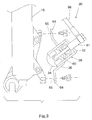
- a front portion of a bicycle is illustrated with a disc brake assembly 12 coupled thereto in accordance with one embodiment of the present invention.
- Bicycles are well known in the art, and thus, the bicycle and its various components will not be discussed or illustrated in detail herein. Rather, it will be apparent to those skilled in the art that the bicycle can be any type of bicycle, e.g., mountain bike, a hybrid bike, downhill bike or a road bike.
- the bicycle basically includes a conventional bicycle frame with a handle bar 14, front and rear forks 16 (only a portion of the front fork shown), front and rear wheels 18 (only a portion of the front wheel shown) and a drive train (not shown).
- the disc brake assembly 12 basically includes a disc brake caliper assembly 20, a disc brake rotor 22 and a brake operating mechanism 24.
- the disc brake caliper assembly 20 is mounted on front fork 16 of the bicycle adjacent the disc brake rotor 22.
- the disc brake rotor 22 is fixedly coupled to front wheel 18 for rotation therewith in a conventional manner.
- the brake operating mechanism 24 is preferably fixedly mounted on handle bar 14 adjacent the hand portion of handle bar 14.
- the brake operating mechanism 24 is operated such that at least one friction member of the disc brake caliper assembly 20 moves from a release position to a braking position. In the release position, the bicycle wheel 18 and the disc brake rotor 22 are free to rotate, while in the braking position a braking force is applied against the disc brake rotor 22 to stop rotation of the bicycle wheel 18 and the disc brake rotor 22.
- the disc brake caliper assembly 20 basically includes a caliper housing 26 with a pair (first and second) of friction members 28a and 28b coupled to the caliper housing 26.
- the (second) friction member 28b is fixedly coupled to the caliper housing 26, while the other (first) friction member 28a is movable coupled to the caliper housing 26.
- a rotor receiving slot is formed between friction members 28a and 28b to receive the disc brake rotor 22.
- the movable friction member 28a (first friction member) is moved by a piston mechanism 30 in response to movement of the brake operating mechanism 24 to apply a braking force on the disc brake rotor 22, as discussed in more detail below.
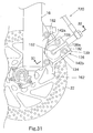
- the caliper housing 26 basically includes a support portion 32 and a first cylinder portion 34 coupled to the support portion 32.
- the caliper housing 26 also preferably includes a mounting portion 36 for coupling with the support portion 32 and the cylinder portion 34 to the front fork 16.
- the support portion 32, the cylinder portion 34 and the mounting portion 36 are each formed of one or more pieces of deformed sheet material such as press formed sheet metal. The various pieces are preferably fixedly coupled together by welding and/or brazing and/or bolted together as discussed below in more detail.
- each of the support portion 32, the cylinder portion 34 and the mounting portion 36 are preferably formed by one or more independent members that are subsequently fixedly coupled together to form the caliper housing 26.
- the cylinder portion 34 is at least an independent member from the support portion 32 such that the cylinder portion 34 can be primarily formed of deformed sheet material.
- the support portion 32 basically includes a first housing part 38a and a second housing part 38b fixedly coupled together.
- the first and second housing parts38a and 38b are fixedly coupled together by a pair of bolts 39a with a pair of nuts 39b threadedly coupled to the bolts 39a.
- the first housing part 38a is preferably constructed of a single piece of deformed sheet material such as press formed sheet metal.
- the second housing part 38b is also preferably formed of a single piece of deformed sheet material such as press formed sheet metal.
- the cylinder portion 34 is preferably fixedly coupled to the first housing part 38a by welding or brazing to form a rigid unitary body with the first housing part 38a.
- each part of the caliper housing 26 is of deformed sheet material, except for the fastening elements (the welds, the bolts and the nuts).
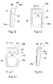
- the second housing part 38b basically includes an (second) attachment plate 44 and a reinforcing flange 46.
- the second housing part 38b is preferably constructed of a single piece of deformed sheet material such press formed sheet metal.
- the attachment plate 44 has a pair of attachment holes 45 formed therein to receive the bolts 39a.
- the reinforcing flange 46 is a substantially U-shaped flange extending from one side of the attachment plate 44.
- the second friction member 28b is attached to the opposite side of the attachment plate 44 from the reinforcing flange 46 at a free end of the attachment plate 44.
- the second friction member 28b is fixedly coupled to the attachment plate 44 via adhesive or glue.
- the reinforcing flange 46 preferably extends at substantially a right angle relative to the attachment plate 44, and includes a transverse section 48 and a pair of longitudinal sections 49.
- the longitudinal sections 49 are tapered toward the attachment plate 44 as the longitudinal sections 49 extend away from the transverse section 48.
- the longitudinal sections 49 extend completely to the free end of the attachment plate 44 such that a lightweight, rigid member is formed.
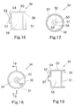
- the (first) cylinder portion 34 basically includes an enlarged section 50 integrally formed with a reduced diameter section 52.
- the cylinder portion 34 is preferably a tubular member that isconstructed of a single piece of deformed sheet material such as press formed sheet metal.
- the cylinder portion 34 is an independent member from the support portion 32 (the first and second housing parts 38a and 38b).
- the enlarged section 50 and the reduced section 52 are preferably cylindrical sections that have a circular-shaped cross section.
- An end plate 54 connects the enlarged section 50 with the reduced section 52 to form a one-piece unitary member.
- the internal surface of the end plate 54 forms an abutment surface for the piston mechanism 30, while the external surface of the end plate 54 forms an attachment surface configured to be supported by the cylinder support flanges 43 of the first housing part 38a.
- the cylinder support flanges 43 are fixedly coupled to the end plate 54 of the cylinder portion 34 by welding or brazing such that the cylinder portion 34 is fixedly coupled to the first housing part 38a.
- the cylinder portion 34 includes a (first) piston chamber 56 with a (first) fluid inlet opening 57 fluidly coupled to the piston chamber 56 and a (first) piston receiving opening 59.
- the piston mechanism 30 is at least partially received in the piston chamber 56.
- the enlarged section 50 of the cylinder portion 34 includes an annular groove 51 designed to engage a portion of the piston mechanism 30, as discussed below in more detail.
- the open end of the reduced diameter section 52 forms the fluid inlet opening 57 of the cylinder portion 34.
- the fluid inlet opening 57 is designed to be directly fixedly coupled to a fluid supply hose 60, as also discussed in more detail below.
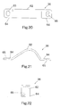
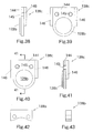
- the mounting portion 36 is preferably a plate-shaped strap member constructed of a single piece of deformed sheet material such as press formed sheet metal.
- the mounting portion 36 basically includes a curved cylinder support section 62 with a pair of mounting sections 64 extending from opposite ends of the curved cylinder support section 62.
- Each of the mounting sections 64 includes a mounting hole 65.
- the mounting sections 64 are utilized to fixedly couple the disc brake caliper assembly 20 to the front fork 16 of the bicycle in a relatively conventional manner.
- the mounting portion 36 is preferably fixedly coupled to both the cylinder portion 34 and the first housing part 38a by welding or brazing. More specifically, the curved cylinder support section 62 is preferably coupled to the external surface of the enlarged section 50 of the cylinder portion 34. Also, the curved cylinder support section 62 is preferably coupled to the inner edges of the side plates 42 of the first housing part 38a. In other words, the mounting portion 36 is preferably fixedly coupled to and arranged between the cylinder portion 34 and the first housing part 38a. Preferably, these members are coupled together by welding or brazing.
- the mounting portion 36 is formed as a one-piece unitary member that is separate from the cylinder portion 34 and the support portion 32 (first housing part 38a and second housing part 38b).
- mounting portion 36 could be integrally formed with the first housing part 38a, as discussed below in reference to another preferred embodiment of the present invention.
- the piston mechanism 30 basically includes a (first) piston 70 movably coupled in the piston chamber 56 and a friction member support portion 72 coupled to the piston 70.
- the piston 70 is that can be constructed of any suitable material.
- the piston 70 can be constructed of machined metallic material such as machined aluminum or a resin with heat resistant characteristics.
- the piston 70 preferably has a step-shaped configuration.
- the friction member support portion 72 is also preferably constructed of a machined metallic material such as machined steel.
- the friction member support portion 72 is releasably coupled to the piston 72 to move with the piston 70 during actuation.
- the piston 70 is normally biased toward a release position from a braking position.
- the piston 70 is moved from the release position to the braking position via fluid pressure supplied by the brake operating mechanism 24 in a conventional manner.
- the piston 70 basically includes a seal portion 74 (first enlarged end) with a central protrusion 76 (second reduced end) extending axially therefrom.
- the seal portion 74 has a plurality of arc-shaped projections 75 extending axially from the opposite side from the central protrusion 76.
- the projections 75 contact the internal contact surface of the end plate 54 of the cylinder portion 34 when the piston 70 is in the release position.
- the projections 75 aid in the transmission of hydraulic pressure. While the projections 75 are illustrated as arc-shaped, it will be apparent to those skilled in the art that other shapes could be utilized if needed and/or desired.
- An annular groove 78 is formed in the external surface of the seal portion 74.
- An O-ring 79 is mounted in the groove 78 to form a fluid tight seal.
- a biasing member (e.g., a cone spring or a coil spring or Belleville washers) 80 is mounted on the central protrusion 76 of the piston 70. One end of the biasing member 80 is arranged to contact the seal portion 74 of the piston 70, while the other end of the biasing member 80 is arranged to contact an annular abutment ring 82.
- the annular ring 82 is preferably a snap ring that is mounted in the annular groove 51 formed in the enlarged section 50 of the cylinder portion 34 to retain the piston 70 within the piston chamber 56.
- the friction member support portion 72 is also preferably a step shaped member. More specifically, the friction member support portion 72 includes a central stump 84 extending from a base portion 86. The central stump 84 includes an annular groove 85 with an O-ring received therein. The central protrusion 76 of the piston 70 includes a stepped bore 88 that is sized and configured to retain the central stump 84 with the O-ring therein. Thus, the friction member support portion 72 is releasable coupled to the piston 70. When the piston 70 is in the release position, the base portion 86 contacts an opposite end of the annular ring 82.
- the brake operating mechanism 24 is designed to actuate the disc brake caliper assembly 20 to apply a forcible gripping action on the brake disc 22 to stop rotation of the front wheel 18.
- the brake operating mechanism 24 basically includes a brake lever 90, a hydraulic or master cylinder 91, a hydraulic or master piston 92, and an actuation fluid reservoir 93.
- the brake operating mechanism 24 is a single unit, which is mounted on the handlebar 14.
- the brake lever 90 includes a mounting portion 94 and a lever portion 95.
- the mounting portion 94 is designed to be clamped onto the handle bar 14 in a conventional manner.
- the mounting portion 94 is integrally formed with the master cylinder 91 such that the master cylinder 91, the master piston 92 and the actuation fluid reservoir 93 are all supported on the mounting portion 94 of the brake lever 90.
- the lever portion 95 is pivotally coupled to the mounting portion 94 for movement between a release position and a braking position. Normally, the lever portion 94 is maintained in the release position in a conventional manner.
- a disc brake caliper assembly 120 is illustrated in accordance with a second embodiment of the present invention.
- Disc brake caliper assembly 120 of this second embodiment is substantially identical to the disc brake caliper assembly 20 of the first embodiment, except that a modified caliper housing 126 is utilized.
- this second embodiment will not be discussed or illustrated in detail herein. Rather, the following description will focus mainly on the differences. However, it will be apparent to those skilled in the art that most of the descriptions of the disc brake caliper assembly 20 of the first embodiment also apply to the disc brake caliper assembly 120 of this second embodiment.
- the caliper housing 126 includes a support portion 132, a cylinder portion 134 and a mounting portion 136.
- the support portion 132 includes a first housing part 138a, a spacer 138b and a second housing part 138c.
- the first and second housing parts 138a and 138c are fixedly coupled together by a pair of bolts 139 with the spacer 138b located therebetween.
- the mounting portion 136 basically includes first and second mounting sections 162, which are integrally formed with the first housing part 138a.
- the first housing part 138a includes an attachment plate 140 with a pair of attachment holes 141 and a pair of side plates 142a and 142b.
- the mounting sections 162 extend from the side plates 142a and 142b.
- a cylinder support opening 143 is formed in the attachment plate 140.
- the first housing part 138a is integrally formed with the mounting sections 162 to form the mounting portion 136 of the caliper housing 126.
- the second housing part 138c includes an attachment plate 144 with a pair of threaded bores 145 formed therein.
- the second friction member 128b is fixedly coupled to the attachment plate 144.
- Two reinforcing flanges 146 extend in a generally longitudinal direction relative to attachment plate 144 and are substantially perpendicular to the attachment plate 144.
- the threaded holes 145 of the attachment plate 144 eliminate the need for the nuts 39b (of the first embodiment).
- the spacer 138b includes a pair of mounting holes formed therein for receiving the bolts 139.
- the cylinder portion 134 is a modified version of the cylinder portion 34 of the first embodiment. Specifically, the cylinder portion 134 includes and enlarged section 150, a reduced diameter section 152 and an end plate 154.
- a piston chamber 156 is formed within the cylinder portion 134 and includes a fluid inlet opening 157 fluidly coupled to the piston chamber 156 and a piston receiving opening 159 arranged at an opposite end of the piston chamber 156 from the fluid inlet opening 157.
- a pair of flanges 151 are formed adjacent the piston receiving opening 159 and extend substantially perpendicularly from the enlarged section 150. Two cutouts or notches 161 are formed on opposite sides of the flanges 151. The flanges contact the attachment plate 144.
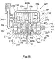
- the disc brake caliper assembly 220 is designed to be used with the brake operating mechanism 24 of the first embodiment, and basically includes a caliper housing 226, a pair (first and second) of friction members 128a and 128b, and a pair of piston mechanisms 230.
- the friction members 228a and 228b are identical to the friction members of the first embodiment. Additionally, each of the piston mechanisms 230 is substantially identical to the piston mechanism 130 of the second embodiment.
- Each of the piston mechanisms 230 basically includes a piston 270 movably coupled in the piston chamber 256 of the corresponding cylinder portion 234 and a friction member support portion 272 coupled to the piston 270.
- the pistons 270 are moved from the release positions to the braking positions via fluid pressure supplied by the brake operating mechanism 24 in a conventional manner.
- Each of the pistons 270 basically includes a seal portion 274 (first enlarged end) with a central protrusion 276 (second reduced end) extending axially therefrom.
- the seal portion 274 has a plurality of arc-shaped projections 275 extending axially from the opposite side from the central protrusion 276.
- the projections 275 contact the internal contact surface of the cylinder portion 234 when the piston 270 is in the release position.
- the projections 275 aid in the transmission of hydraulic pressure.
- the projections 275 are preferably arc-shaped as in the prior embodiments, but longer in the axial direction.
- An annular groove 278 is formed in the external surface of the seal portion 274.
- An O-ring 279 is mounted in the groove 278 to form a fluid tight seal.
- a biasing member (e.g., Belleville washers) 280 is mounted on the central protrusion 276 of each of the pistons 270.
- the first and second pistons 270 are normally biased toward their release positions by the first and second biasing members 280, respectively.
- Each biasing member 280 in this embodiment is shorter in the axial direction than in the prior embodiments, since there are two piston mechanisms 230 with one biasing member 280 for each piston 270.
- One end of the biasing member 280 is arranged to contact the seal portion 274 of the piston 270, while the other end of the biasing member 280 is arranged to contact an annular abutment ring 282.
- the friction member support portions 272 have the friction members 228a and 228b fixedly coupled thereto via adhesive or glue.
Landscapes
- Engineering & Computer Science (AREA)
- General Engineering & Computer Science (AREA)
- Mechanical Engineering (AREA)
- Braking Arrangements (AREA)
Abstract
Description
Claims (39)
- A disc brake caliper assembly (20, 120, 220) comprising:a caliper housing (26, 126, 226) including a support portion (32, 132, 232) and a first cylinder portion (34, 134, 234) coupled to said support portion, said first cylinder portion (34, 134, 234) having a first piston chamber (56, 156, 256) with a first fluid inlet opening (57, 157, 257) fluidly coupled to said first piston chamber (56, 156, 256) and a first piston receiving opening (59, 159), said first cylinder portion (34, 134, 234) being an independent component from said support portion;first and second friction members (28a, 28b; 128a, 128b; 228a, 228b) coupled to said caliper housing (26, 126, 226) to form a rotor receiving slot therebetween, at least said first friction member (28a, 128a, 228a) being movably coupled to said caliper housing (26, 126, 226); anda first piston movably coupled in said first piston chamber (56, 156, 256) of said caliper housing (26, 126, 226) to move said first friction member (28a, 128a, 228a) between a release position and a braking position.
- The disc brake caliper assembly (20, 120, 220) according to claim 1, wherein
said first cylinder portion (34, 134, 234) is constructed of deformed sheet material. - The disc brake caliper assembly (20, 120, 220) according to claim 1 or 2, wherein
said first cylinder portion (34, 134, 234) is constructed of press formed sheet metal. - The disc brake caliper assembly (20, 120, 220) according to any of the preceding claims, wherein
said support portion (32, 132, 232) is at least partially formed of metal and said first cylinder portion (34, 134, 234) is fixedly coupled to said support portion (32, 132, 232) by welding or brazing. - The disc brake caliper assembly (20, 120, 220) according to any of the preceding claims, wherein
said support portion (32, 132, 232) includes a first housing part (38a, 138a, 238a) with said first cylinder portion (34, 134, 234) fixedly coupled thereto and a second housing part (38b, 138c, 238c) coupled to said first housing part (38a, 138a, 238a) and supporting said second friction member (28b, 128b, 228b). - The disc brake caliper assembly (20, 120, 220) according to claim 5, wherein
said first and second housing parts (38a, 138a, 238a; 38b, 138c, 238c) are formed of deformed sheet material. - The disc brake caliper assembly (20, 120, 220) according to claim 5 or 6, wherein
said support portion (32, 132, 232) includes a mounting portion (36, 136, 236) fixedly coupled with said first housing part (38a, 138a, 238a) and said first cylinder portion (34, 134, 234). - The disc brake caliper assembly (20, 120) according to claims 5 to 7, wherein
said mounting portion (36, 136) is a strap member with a pair of mounting sections (64, 162). - The disc brake caliper assembly (20, 120) according to claims 5 to 8, wherein
said strap member is constructed of deformed sheet material. - The disc brake caliper assembly (20, 120) according to claims 5 to 9, wherein
said first cylinder portion (34, 134), said first housing part (38a, 138a) and said strap member are constructed of press formed sheet metal and are fixedly coupled together by welding or brazing. - The disc brake caliper assembly (20, 120, 220) according to claim 5 or 6, wherein
said first and second housing parts (138a, 238a; 138c, 238c) are fixedly coupled together with a spacer (138b, 238b) coupled between said first and second housing parts (38a, 138a, 238a; 38b, 138c, 238c). - The disc brake caliper assembly (20, 120, 220) according to claim 5, wherein
said first housing part (138a) includes a pair of mounting sections (162) integrally formed therewith. - The disc brake caliper assembly (20, 120, 220) according to claim 5, wherein
said second friction member (28b, 128b, 228b) is fixedly coupled to said second housing part (38b, 138c, 238c). - The disc brake caliper assembly (20, 120, 220) according to claim 5, wherein
said first and second housing parts (38a, 138a, 238a; 38b, 138c, 238c) are constructed of press formed sheet metal. - The disc brake caliper assembly (20, 120, 220) according to claim 5, wherein
said second friction part (28b, 128b, 228b) is movably coupled to said second housing part (38b, 138c, 238c) to move said second friction member (28b, 128b, 228b) between a release position and a braking position. - The disc brake caliper assembly (20, 120, 220) according to claim 15, wherein
said caliper housing (26, 126, 226) includes a second cylinder portion fixedly coupled to said second housing part (38b, 138c, 238c), said second cylinder portion having a second piston chamber a second fluid inlet opening fluidly coupled to said second piston chamber and a second piston receiving opening with a second piston movably coupled therein to move said second friction member (28b, 128b, 228b) between said release position and said braking position. - The disc brake caliper assembly (20, 120, 220) according to claim 15 or 16, wherein
said first fluid inlet opening (57, 157, 257) of said first cylinder portion (34, 134, 234) is fixedly coupled to a fluid supply hose (60, 260). - The disc brake caliper assembly (20, 120, 220) according to claims 15 to 17, wherein
said first cylinder portion (34, 134, 234) includes a first fluid outlet opening in fluid communication with said first piston chamber (56, 156, 256) and said second fluid inlet opening of said second cylinder portion. - The disc brake caliper assembly (20, 120, 220) according to claims 15 to 18, wherein
said first fluid outlet opening of said first cylinder portion (34, 134, 234) and said second fluid inlet opening of said second cylinder portion are fixedly coupled to opposite ends of a fluid connection hose. - The disc brake caliper assembly (20, 120, 220) according to claims 15 to 19, wherein
said second cylinder portion includes an access opening formed at a free end thereof with a sealing cap mounted in said access opening. - The disc brake caliper assembly (20, 120, 220) according to claims 15 to 20, wherein
said second cylinder portion is identical to said first cylinder portion. - The disc brake caliper assembly (20, 120, 220) according to claim 15 or 16, wherein
said first and second pistons are normally biased toward said release positions by first and second biasing members, respectively. - The disc brake caliper assembly (20, 120, 220) according to claim 22, wherein
said first and second biasing members are cone springs. - The disc brake caliper assembly (20, 120, 220) according to any of the preceding claims, wherein
said first cylinder portion (34, 134, 234) and said fluid supply hose are constructed metal and are fixedly coupled together by welding or brazing. - The disc brake caliper assembly (20, 120, 220) according to any of the preceding claims, wherein
said first piston (70) is normally biased toward said release position by a first biasing member. - The disc brake caliper assembly (20, 120, 220) according to claim 25, wherein
said first biasing member is a cone spring. - The disc brake caliper assembly (20, 120, 220) according to claim 25 or 26, wherein
said first cylinder portion (34, 134, 234) includes an abutment ring coupled therein to engage one end of said biasing member and the first piston (70) includes a contact surface arranged to engage the other end of said biasing member. - The disc brake caliper assembly (20, 120, 220) according to claims 25 to 27, wherein
said first piston is a step shaped member with a first enlarged end arranged adjacent said first fluid inlet opening to form said contact surface and a second reduced end arranged adjacent said first friction member. - The disc brake caliper assembly (20, 120, 220) according to claims 25 to 28, wherein
said enlarged end includes an annular external groove with an O-ring received therein to form a fluid tight seal with an interior wall of said first cylinder portion. - The disc brake caliper assembly (20, 120, 220) according to claims 25 to 28, wherein
said enlarged end includes a plurality of protrusions extending axially therefrom to form a free end of said first piston (70). - The disc brake caliper assembly (20, 120, 220) according to claim 30, wherein
each of said protrusions is arc-shaped. - The disc brake caliper assembly (20, 120, 220) according to claim 28, wherein
said first friction member (28a, 128a, 228a) is coupled to said reduced end and arranged to contact said abutment ring when said first piston (70) is in said release position. - The disc brake caliper assembly (20, 120, 220) according to claim 32, wherein
said reduced end has an opening formed in a free end thereof and said first friction member (28a, 128a, 228a) includes a projection coupled within said opening. - The disc brake caliper assembly (20, 120, 220) according to any of the preceding claims, wherein
said support portion (32, 132, 232) includes a first housing part (38a, 138a, 238a) with an attachment plate (40, 140, 240) and a first side plate extending from said attachment plate (40, 140, 240) to support said first cylinder portion. - The disc brake caliper assembly (20, 120, 220) according to claim 34, wherein
said first housing part (38a, 138a, 238a) includes a second side plate extending from said attachment plate (40, 140, 240) to form a substantially U-shaped member. - The disc brake caliper assembly (20, 120, 220) according to claim 34 or 35, wherein
each of said first and second side plates includes a cylinder support flange arranged to contact an end plate of said first cylinder portion (34, 134, 234). - The disc brake caliper assembly (20, 120, 220) according to claim 34 or 35, wherein
each of said first and second side plates is a substantially L-shaped member. - The disc brake caliper assembly (20, 120, 220) according to claim 34, wherein
said support portion (32, 132, 232) includes a second housing part coupled to said attachment plate. - A disc brake caliper assembly (20, 120, 220) comprising:a caliper housing (26, 126, 226) including a support portion (32, 132, 232) and a first cylinder portion (34, 134, 234) coupled to said support portion, said first cylinder portion (34, 134, 234) being formed of deformed sheet material, said first cylinder portion (34, 134, 234) having a first piston chamber (56, 156, 256) with a first fluid inlet opening (57, 157, 257) fluidly coupled to said first piston chamber (56, 156, 256) and a first piston receiving opening (59, 159);first and second friction members (28a, 28b; 128a, 128b; 228a, 228b) coupled to said caliper housing (26, 126, 226) to form a rotor receiving slot therebetween, at least said first friction member (28a, 128a, 228a) being movably coupled to said caliper housing (26, 126, 226); anda first piston movably coupled in said first piston chamber (56, 156, 256) of said caliper housing (26, 126, 226) to move said first friction member (28a, 128a, 228a) between a release position and a braking position.
Applications Claiming Priority (2)
| Application Number | Priority Date | Filing Date | Title |
|---|---|---|---|
| US903860 | 2001-07-13 | ||
| US09/903,860 US6510926B1 (en) | 2001-07-13 | 2001-07-13 | Disc brake caliper assembly |
Publications (3)
| Publication Number | Publication Date |
|---|---|
| EP1275578A2 true EP1275578A2 (en) | 2003-01-15 |
| EP1275578A3 EP1275578A3 (en) | 2003-12-17 |
| EP1275578B1 EP1275578B1 (en) | 2006-03-15 |
Family
ID=25418175
Family Applications (1)
| Application Number | Title | Priority Date | Filing Date |
|---|---|---|---|
| EP02013718A Expired - Lifetime EP1275578B1 (en) | 2001-07-13 | 2002-06-20 | Disc brake caliper assembly |
Country Status (7)
| Country | Link |
|---|---|
| US (1) | US6510926B1 (en) |
| EP (1) | EP1275578B1 (en) |
| JP (1) | JP3994030B2 (en) |
| CN (1) | CN1246180C (en) |
| CZ (1) | CZ20022275A3 (en) |
| DE (1) | DE60209834T2 (en) |
| TW (1) | TWI241261B (en) |
Cited By (3)
| Publication number | Priority date | Publication date | Assignee | Title |
|---|---|---|---|---|
| WO2005123491A1 (en) * | 2004-06-21 | 2005-12-29 | Freni Brembo S.P.A. | Disc brake caliper |
| RU2508219C1 (en) * | 2012-10-24 | 2014-02-27 | Общество с ограниченной ответственностью "Трейд-Импорт" | Bicycle disc brake |
| IT202100026324A1 (en) * | 2021-10-14 | 2023-04-14 | Raicam Driveline S R L | BRAKE PADS WITH BASE IN PLASTIC MATERIAL |
Families Citing this family (21)
| Publication number | Priority date | Publication date | Assignee | Title |
|---|---|---|---|---|
| US6761251B1 (en) * | 2003-05-22 | 2004-07-13 | Chun Te Wen | Hydraulic brake device for a bicycle |
| DE102005061903A1 (en) * | 2005-12-23 | 2007-06-28 | Gustav Magenwirth Gmbh & Co. Kg | Connecting piece for hydraulic lead to a brake fork, a brake fork and a hydraulic brake, has catch extending sideways to the plane of ring-forming region |
| DE102006001133A1 (en) * | 2006-01-09 | 2007-07-12 | Robert Bosch Gmbh | Electromechanical friction brake |
| CN101498346A (en) * | 2008-01-31 | 2009-08-05 | 温芫鋐 | Disc brake buffer device |
| US20090211854A1 (en) * | 2008-02-25 | 2009-08-27 | Wen Yuan-Hung | Buffer device of disk brake |
| US8813936B2 (en) * | 2008-07-25 | 2014-08-26 | Eaton Corporation | Force transmitting assembly |
| US8162354B2 (en) | 2008-07-25 | 2012-04-24 | Shimano Inc. | Twistable hydraulic brake hose unit |
| DE102011007652A1 (en) * | 2011-04-19 | 2012-10-25 | Gustav Magenwirth Gmbh & Co. Kg | Brake and procedure for your assembly |
| US20130048444A1 (en) * | 2011-08-25 | 2013-02-28 | Shimano Inc. | Bicycle disc brake caliper |
| US9365260B2 (en) * | 2012-04-18 | 2016-06-14 | Shimano Inc. | Bicycle hydraulic operating device |
| DE102012008003A1 (en) * | 2012-04-20 | 2013-10-24 | Knorr-Bremse Systeme für Nutzfahrzeuge GmbH | Disc brake for vehicles |
| CN103122956A (en) * | 2013-01-22 | 2013-05-29 | 陈政文 | Double-push disc type braking structure |
| US9227691B2 (en) | 2013-06-28 | 2016-01-05 | Shimano Inc. | Bicycle brake caliper assembly |
| US9533733B2 (en) | 2013-06-28 | 2017-01-03 | Shimano Inc. | Disc brake caliper and disc brake caliper assembly |
| DE102013109861B3 (en) * | 2013-09-10 | 2014-11-27 | GEDIA Gebrüder Dingerkus GmbH | Brake caliper for disc brakes of motor vehicles |
| US9457868B2 (en) | 2014-08-06 | 2016-10-04 | Shimano Inc. | Bicycle hydraulic quick-release apparatus and bicycle frame |
| US9752633B2 (en) * | 2016-01-18 | 2017-09-05 | Shimano Inc. | Bicycle disc brake rotor |
| CN106043575A (en) * | 2016-07-12 | 2016-10-26 | 温芫鋐 | Disc protective cover |
| US10427750B2 (en) * | 2017-04-10 | 2019-10-01 | Shimano Inc. | Bicycle disc brake caliper assembly |
| IT201700046888A1 (en) * | 2017-05-02 | 2018-11-02 | Campagnolo Srl | Bicycle brake disc assembly |
| DE102019106706A1 (en) * | 2019-03-15 | 2020-09-17 | Ingenieurbüro für Automatisierungstechnik Schubert GbR ( vertretungsberechtigter Gesellschafter: Mike Schubert, 09465 Sehmatal-Sehma) | Hydraulic brake and vehicle |
Family Cites Families (8)
| Publication number | Priority date | Publication date | Assignee | Title |
|---|---|---|---|---|
| USRE24996E (en) * | 1957-02-25 | 1961-06-06 | Disc brakes | |
| DE2308909A1 (en) * | 1973-02-23 | 1974-08-29 | Fichtel & Sachs Ag | DISC BRAKE FOR BICYCLES |
| US4031986A (en) * | 1974-03-25 | 1977-06-28 | Thompson Tom H | Disk brake construction having stamped support |
| US4370918A (en) * | 1980-03-24 | 1983-02-01 | Pringle William L | Fluid cylinder assembly |
| US5282521A (en) * | 1992-10-02 | 1994-02-01 | General Motors Corporation | Shell disc brake |
| JP3022187B2 (en) | 1994-08-08 | 2000-03-15 | トヨタ自動車株式会社 | Disc brake split caliper |
| DE19861380A1 (en) * | 1998-03-13 | 2006-08-31 | Gustav Magenwirth Gmbh & Co. Kg | disc brake |
| US6340074B1 (en) * | 2000-04-06 | 2002-01-22 | Avid Llc | Pad wear compensator for a disc brake caliper |
-
2001
- 2001-07-13 US US09/903,860 patent/US6510926B1/en not_active Expired - Lifetime
-
2002
- 2002-04-22 TW TW091108236A patent/TWI241261B/en not_active IP Right Cessation
- 2002-05-23 CN CNB021203288A patent/CN1246180C/en not_active Expired - Fee Related
- 2002-06-17 JP JP2002175800A patent/JP3994030B2/en not_active Expired - Fee Related
- 2002-06-20 DE DE60209834T patent/DE60209834T2/en not_active Expired - Lifetime
- 2002-06-20 EP EP02013718A patent/EP1275578B1/en not_active Expired - Lifetime
- 2002-06-28 CZ CZ20022275A patent/CZ20022275A3/en unknown
Non-Patent Citations (1)
| Title |
|---|
| None |
Cited By (3)
| Publication number | Priority date | Publication date | Assignee | Title |
|---|---|---|---|---|
| WO2005123491A1 (en) * | 2004-06-21 | 2005-12-29 | Freni Brembo S.P.A. | Disc brake caliper |
| RU2508219C1 (en) * | 2012-10-24 | 2014-02-27 | Общество с ограниченной ответственностью "Трейд-Импорт" | Bicycle disc brake |
| IT202100026324A1 (en) * | 2021-10-14 | 2023-04-14 | Raicam Driveline S R L | BRAKE PADS WITH BASE IN PLASTIC MATERIAL |
Also Published As
| Publication number | Publication date |
|---|---|
| EP1275578A3 (en) | 2003-12-17 |
| JP3994030B2 (en) | 2007-10-17 |
| CN1246180C (en) | 2006-03-22 |
| JP2003028209A (en) | 2003-01-29 |
| CN1397467A (en) | 2003-02-19 |
| US6510926B1 (en) | 2003-01-28 |
| EP1275578B1 (en) | 2006-03-15 |
| TWI241261B (en) | 2005-10-11 |
| DE60209834T2 (en) | 2006-10-19 |
| DE60209834D1 (en) | 2006-05-11 |
| CZ20022275A3 (en) | 2003-03-12 |
| US20030010580A1 (en) | 2003-01-16 |
Similar Documents
| Publication | Publication Date | Title |
|---|---|---|
| EP1275578B1 (en) | Disc brake caliper assembly | |
| EP1122162B1 (en) | Disc brake assembly | |
| US6401882B1 (en) | Heat insulator for disc brake | |
| US6347689B1 (en) | Roll back seal for disc brake | |
| EP0994269B1 (en) | Disk brake assembly | |
| US9551389B2 (en) | Bicycle disc brake caliper | |
| US5632362A (en) | Bicycle disc brake | |
| EP1308382A2 (en) | Shim and bicycle assembly with shim | |
| US8534428B2 (en) | One piece hydraulic disc brake caliper with one way plumbing | |
| EP1046575A2 (en) | Ventilated pad for a bicycle disc brake | |
| EP1122161B1 (en) | Bicycle disk brake | |
| RU2565156C2 (en) | Weight-reduced composite set of spring brake drive | |
| TWI845080B (en) | Flat mount brake caliper for bicycle | |
| EP1304496B1 (en) | Disk brake for vehicle with bar handle | |
| US20240286706A1 (en) | Non-circular brake piston | |
| CN118959475A (en) | Non-round brake piston |
Legal Events
| Date | Code | Title | Description |
|---|---|---|---|
| PUAI | Public reference made under article 153(3) epc to a published international application that has entered the european phase |
Free format text: ORIGINAL CODE: 0009012 |
|
| AK | Designated contracting states |
Kind code of ref document: A2 Designated state(s): AT BE CH CY DE DK ES FI FR GB GR IE IT LI LU MC NL PT SE TR |
|
| AX | Request for extension of the european patent |
Free format text: AL;LT;LV;MK;RO;SI |
|
| PUAL | Search report despatched |
Free format text: ORIGINAL CODE: 0009013 |
|
| AK | Designated contracting states |
Kind code of ref document: A3 Designated state(s): AT BE CH CY DE DK ES FI FR GB GR IE IT LI LU MC NL PT SE TR |
|
| AX | Request for extension of the european patent |
Extension state: AL LT LV MK RO SI |
|
| 17P | Request for examination filed |
Effective date: 20031205 |
|
| 17Q | First examination report despatched |
Effective date: 20040429 |
|
| AKX | Designation fees paid |
Designated state(s): DE FR GB IE IT NL |
|
| GRAP | Despatch of communication of intention to grant a patent |
Free format text: ORIGINAL CODE: EPIDOSNIGR1 |
|
| GRAS | Grant fee paid |
Free format text: ORIGINAL CODE: EPIDOSNIGR3 |
|
| GRAA | (expected) grant |
Free format text: ORIGINAL CODE: 0009210 |
|
| AK | Designated contracting states |
Kind code of ref document: B1 Designated state(s): DE FR GB IE IT NL |
|
| REG | Reference to a national code |
Ref country code: GB Ref legal event code: FG4D |
|
| REG | Reference to a national code |
Ref country code: IE Ref legal event code: FG4D |
|
| REF | Corresponds to: |
Ref document number: 60209834 Country of ref document: DE Date of ref document: 20060511 Kind code of ref document: P |
|
| PG25 | Lapsed in a contracting state [announced via postgrant information from national office to epo] |
Ref country code: IE Free format text: LAPSE BECAUSE OF NON-PAYMENT OF DUE FEES Effective date: 20060620 Ref country code: GB Free format text: LAPSE BECAUSE OF NON-PAYMENT OF DUE FEES Effective date: 20060620 |
|
| RAP2 | Party data changed (patent owner data changed or rights of a patent transferred) |
Owner name: SHIMANO INC. |
|
| NLT2 | Nl: modifications (of names), taken from the european patent patent bulletin |
Owner name: SHIMANO INC. Effective date: 20060802 |
|
| ET | Fr: translation filed | ||
| PLBE | No opposition filed within time limit |
Free format text: ORIGINAL CODE: 0009261 |
|
| STAA | Information on the status of an ep patent application or granted ep patent |
Free format text: STATUS: NO OPPOSITION FILED WITHIN TIME LIMIT |
|
| 26N | No opposition filed |
Effective date: 20061218 |
|
| GBPC | Gb: european patent ceased through non-payment of renewal fee |
Effective date: 20060620 |
|
| PGFP | Annual fee paid to national office [announced via postgrant information from national office to epo] |
Ref country code: IT Payment date: 20080625 Year of fee payment: 7 |
|
| PGFP | Annual fee paid to national office [announced via postgrant information from national office to epo] |
Ref country code: NL Payment date: 20080603 Year of fee payment: 7 |
|
| PGFP | Annual fee paid to national office [announced via postgrant information from national office to epo] |
Ref country code: FR Payment date: 20080617 Year of fee payment: 7 |
|
| NLV4 | Nl: lapsed or anulled due to non-payment of the annual fee |
Effective date: 20100101 |
|
| REG | Reference to a national code |
Ref country code: FR Ref legal event code: ST Effective date: 20100226 |
|
| PG25 | Lapsed in a contracting state [announced via postgrant information from national office to epo] |
Ref country code: FR Free format text: LAPSE BECAUSE OF NON-PAYMENT OF DUE FEES Effective date: 20090630 |
|
| PG25 | Lapsed in a contracting state [announced via postgrant information from national office to epo] |
Ref country code: NL Free format text: LAPSE BECAUSE OF NON-PAYMENT OF DUE FEES Effective date: 20100101 |
|
| PGFP | Annual fee paid to national office [announced via postgrant information from national office to epo] |
Ref country code: DE Payment date: 20100616 Year of fee payment: 9 |
|
| PG25 | Lapsed in a contracting state [announced via postgrant information from national office to epo] |
Ref country code: IT Free format text: LAPSE BECAUSE OF NON-PAYMENT OF DUE FEES Effective date: 20090620 |
|
| REG | Reference to a national code |
Ref country code: DE Ref legal event code: R119 Ref document number: 60209834 Country of ref document: DE Effective date: 20120103 |
|
| PG25 | Lapsed in a contracting state [announced via postgrant information from national office to epo] |
Ref country code: DE Free format text: LAPSE BECAUSE OF NON-PAYMENT OF DUE FEES Effective date: 20120103 |